Adding some Arduino Functionality ~ FPM5
12/03/2016 ~ Update of Progress on the FPM5
I should start by saying that I have been receiving a lot of world wide input on my "clunky" solution to changing bands and having the display read correctly. In quick review my "clunky" approach was to move the band switch to the band of choice and then hit a momentary Push Button and Shazam! the display would read correctly and as a bonus the correct filters would be selected. The inputs received were in the "bowling lane" of simply move the band switch and the display will read correctly. I used the term bowling lane to reflect a large path of approaches versus a narrow line.
Some suggestions worked, others didn't and some worked better than others. The root cause is that I am using then analog pins for the band switch input. As the Oracle of Italy and one of the founders of the Arduino project, Massimo Banzi stated in his tutorial "you could read the random noise on one of the analog pins and use that for a random number generator" and that my friend is without anything even connected to the pin. So a lot can happen and does! Several early suggestions were to use either the internal software pull up (Arduino 1.0.1 or later) or to physically install pull up resistors. By doing this there is 5 volts on the pins and random noise is ignored. Thus to activate the band the pin is pulled low to ground through the switch contact again no random noise. Thus the analog pin is at 5 volts or ground and nothing in between!
In reality nothing to date works as well as my clunky solution; but I am sure with more effort the software solutions will prevail. This is where my lack of software genes, advanced age and frankly not knowing anything has come home to roost. But I do thank all who have given me input --BTW I have picked up a few new tricks that will prove helpful in other things I will do.
Oh in tripping through the options you can have for this blog --after over a year I found out you can actually search my blog inputs --so look for the search box. I did try it and found it works. But hey what do I know. The comment from Sgt. Schultz in the TV Comedy, Hogan's Heroes: "I don't know nothing" is well applied to me personally!
73's
Pete N6QW
12/02/2016 ~ More 75M contacts, Software Fixes and Front Panel work.
Today had a couple of more 75M contacts and this time we made the 400 mile hop to Sacramento running 100 watts and got an excellent signal strength and audio report. The 20 Meter output has increased but is still only about 40 watts. I do notice a tendency for oscillation if you crank the power higher on 20 Meters --so my haywire, ground loop, poor shielding resulting from the "al fresco" layout will be further evaluated once I move to the box and have better grounds, shorter wires and shielding.
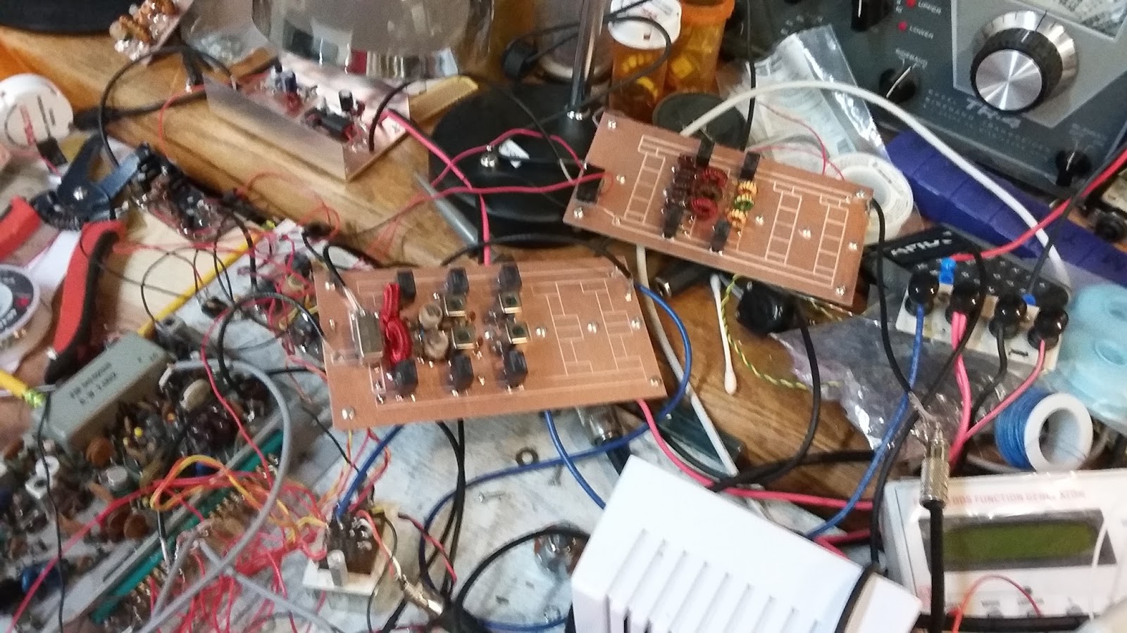
Today I installed the Arduino/Si5351 literally on the front panel. The TFT uses four mounting holes. Instead of a nut on the four screws I installed a 3/4 aluminum 4-40 pillar. I then made a vertical sub-chassis that was just slightly larger than the prototype board I am using for the Arduino/Si5351. So the drill is that the Arduino/Si5351 will be mounted on the vertical chassis which in turn picks up the 4 mounting pillars holding the TFT color display in place. This conserves space and makes this more compact. Once again I used right angle SMA connectors off of the Si5351 board.
 |
Rear view of the front panel and the Arduino/Si5351 board.
73's
Pete N6QW
|
12/01/2016 ~ News Flash -- 1st contact on 75 Meters
I still have the crude 3 position "bandswitch" (two DPDT toggle switches) which controls the BPF and LPF banks and for the most part have only listened on 75 and 20M. All of the QSO's so far (well over 200) have been on 40 Meters.
So here in the 12th month I thought I would try a contact on 75M. It works! Today I had a nice 15 Minute chat with Bill, K6GZ located in Hesperia, CA and now confirmed that the FPM 5 is air worthy on 75M.
Some initial tests into a dummy load on 20M have been less than satisfactory as the output is really low--like less than 200 MW. I will be chasing that down and possible problems are I goofed on the BPF and LPF calculations or some of the earlier amplifier stages tend to favor the lower frequencies. If all worked the first time then there would be no fun, no hair pulling and no drinking!
Greg VK1VXG in response to my post of yesterday has scratched out a solution to the band switching that involves less hardware, really simple programming and consists mainly of dropping the water level versus building a completely new higher bridge. Thanks Greg! Now I have some more Arduino work to challenge my feeble brain.
73's
Pete N6QW
11/30/2016
For those who have just joined us, the project currently on the workbench is taking the mainboard out of a 1970's hallicrafters FPM300 and building a whole new transceiver around that board. The original 1970's FPM300 was a hybrid radio using tubes in the driver and final stages. For my project I have added the Si5351 for the frequency generation and carrier oscillator and along the way added a 128 X 160 color display. The rig is designed for QRP operation at 5 watts but can be configured to run 700 watts out. The rig is now working on three bands and soon the other two bands will be added. At completion it will operate on 80, 40, 20, 15 and 10 meters just like the original FPM300.
Putting the new rig on multiple bands was to be done using a conventional 5 position panel mounted switch. Sure I could have used a keypad and simply punched a key and the rig would have been on a new band. A year ago I did that with a Ten Tec Model 150 which formerly was a crystal controlled commercial transceiver. But this time I wanted to have a rotary selector switch to select the proper Band Pass and Low Pass filters. Besides this gave me a chance to learn to make circular dial plates on my CNC mill. BTW that adventure did take several tries before I figured out the indexing was 30 degrees and not 36 degrees! The band pass and low pass filter elements use a common buss with pairs of relays at each end of the networks. Then by applying power the correct sets of BPF's and LPF's are put in line on the band you want to work.
The following photos show the dial plate, the rig "al fresco" operating only on 40M and the third photo the addition of the BPF and LPF boards which now has it operating on 80, 40 and 20 Meters. I was having a problem with the 20M band --the rig was deaf. I thought perhaps I had a problem with the 42IF123 IF transformers that were modified to work on 20 Meters and so now the 42IF123 transformer style BPF has been replaced with a discrete component BPF that was first simulated in LT Spice. BUT that still didn't fix the deaf problem. Then I discovered that I had not soldered the ground pin on one of the two 20M LPF relays to the ground plane. So no signal was being switched into the 20 Meter LPF from the antenna buss. A quick dab of solder and peaking of the BPF and it now is working on 20M. A check of my work after I soldered in the parts would have found that problem early on. I just got in a hurry.
 |
| Dial Plate |
 |
| Cool Blue Front Panel |
 |
| Relay selected Band Pass and Low Pass Filters |
The Arduino Magic!
The initial thoughts on how the band switching would work was to set the LO range on the Si5351 from 160 to 10 Meters in one continuous band. If I was say on 40 Meters, and wanted to QSY to 20 Meters I would change the band switch so it would select the 20M sets of filters and then I would place the LO on the 1 MHz step range and crank it from 7 MHz to 14 MHz and then return the step range back to 100 Hz. Now I was on 20 Meters. A few times of doing this and I convinced myself this was all wrong. There had to be a way so when I put the band switch on 20 Meters going from say 40 Meters that the display would follow and there was no cranking of the encoder! Boom put it on 20 and it was on 20 Meters! [I finally did get awful close to this approach.]
This is one of those tasks that looks easy but is really hard. Now I had done this with a keypad -- even on this same board back in 2014; but for this application it was now a band switch. Thus I had to look at how this could be done. Since I am using an Arduino Nano there are 8 analog pins A0 - A7. Well immediately you lose A3 which is the encoder step pin and A5 and A5 which are the I2C pins SDA and SCL which are needed for the Si5351. So this leaves 5 pins, A0 - A2 and A6, A7. Perfect! So now the task was to write code that would detect a high condition on a particular analog pin and then execute code so that a starting frequency for a particular band is loaded into the Si5351. The starting frequencies are as follows: 3.8 MHz, 7.2 MHz, 14.2 MHz, 21.3 MHz and 28.4 MHz.
My initial efforts were partially successful in that I could "high" one of the analog pins and indeed the display would follow depending which band was selected and that is where my success stopped. Because of the way I wrote the code and the way I was detecting the high condition I could tune a couple of steps and then the display would reset itself to the starting frequency. No matter what I tried --every time through the loop the Arduino was doing exactly what I stated in the code --it would reset itself to the start up frequency!
Now for those seasoned Arduino programmers I can see you snickering and laughing up a storm and saying like the Geico ad "everyone knows you don't do that". Finally I thought of contacting a real resource that has been invaluable in helping me through many an Arduino maze. That person is DuWayne, KV4QB! [BTW check his blog --he has done some amazing work and has a 3D printer -- now that will be a common tool you will find in future ham shacks.] In an email exchange DuWayne said something that was the key that unlocked the door to the solution. He said you have to watch out for noise pulses that may be triggering the circuit. There it was right in front of me! PULSES!!!!!
The Arduino works on a loop principle, where at a specific clock frequency the process involves going through the loop looking for any changes. With my band switch which is a two pole 5 position one set of poles controls the filters and the other pole would apply 5 VDC to the analog pin that corresponded to the band selected. There was the problem -- 5 VDC was being constantly applied to the analog pin! Thus every time through the loop it would reset itself to the table of start up frequencies for each band. So enter DuWayne's comment about noise pulses. The solution was to have a pulse appear, one time, at the analog pin, have that detected, the frequency loaded and the next time through the loop there was no pulse present so the logic would not reset itself to the start up frequency every time through the loop!
Finally realizing this was the possible solution I took a jumper wire connected to 5 VDC at one end and the just tapped one of the analog pins and quickly removed the jumper. Boom --the display read the start up frequency and then tuned normally. Thinking back to when I used the keypad --that is exactly what happened --the keypad was a momentary switch and essentially supplied the pulse to switch the LO frequency. So now the answer was to have a pulse supplied just once, have it detected and then no more pulses.
So here is what became the final solution. There were two digital pins available: D6 and D7. Using a panel mounted momentary pushbutton switch connected to D6, engaging that switch generates a pulse which is the output on Pin D7. I experimented with different pulse durations and now have a 50 millisecond pulse appear on Pin D7 when the push button is engaged and connected to Pin D6. The output from D7 is now connected to the second pole on the band switch so that the pulse is routed to and in sync with the PBF's and LPF's
Ok here in the un-elegant solution. I have set the normal startup frequency to 00.000.000. So with the power applied, where ever the band switch is set (or left at the last operation) the appropriate set of Band Pass and Low Pass Filters are selected but until the momentary Push Button is engaged the rig will be dead. A simple tap on the PB will put the display on the proper band. Now lets say you are on 40 Meters and move the band switch to 20M. Now the appropriate BPF and LPF will be engaged but the LO and display will still be on 40 Meters. A quick tap of the PB will move the LO and display to align with the proper filters for the 20 Meter band.
KV4QB had some sage advice about noise pulses. Probably thet next iteration will be to rewrite the code so the pins are always high via pull up resistors and that the condition that is detected is a negative pulse (LOW condition). This way, being high all of the time would not cause a triggering by noise pulses.
Now it would be nice if this was all automatic -- but I haven't found a clever way of making a single pulse without some sort of manual intervention. I am sure the Arduino illuminati have that answer but it was not apparent to me. Really important here was the journey as I learned a lot about how to do things with the Arduino
In passing there are two sub-routines in my code that are associated with changing the LO frequency and the display. The first is the detection phase and the second involves what action is taken once a specific band is detected via the pulsed input. This is a great application of the Arduino "switch" case functionality.
Once I get the code cleaned up I will post it on the blog as a notepad document. Oh another of the digital pins, D4 detects when the PTT is initiated and just so you know the display will show:
 |
| ON THE AIR |
73's
Pete N6QW