More Detail on the Design and Alternatives in the Simpleceiver Receiver Project.
Addendum: 12/05/2015 40 Meter CW Band Pass Filter
Addendum #2: 12/06/2015 "Mea Culpa" for the improper use of "die in the wool" (Crystal Filters)
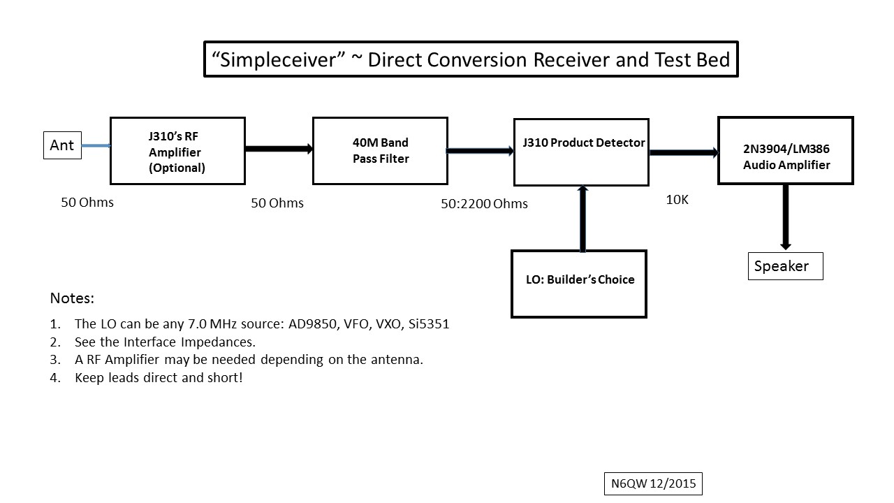
Based on some inputs I have received, I wanted to explore several "details' of the design and also to explore the use of IF frequencies other than 12.096 MHz. So let us begin by looking at the "gain adjustment" features of the Simpleceiver design. Currently there are three stages which can manually have their gain adjusted which includes the RF Amplifier Stage and the two IF Amplifier stages. The next step of course would be to replace the manual gain controls with an AGC circuit.
The use of the Dual Gate MOSFET was not accidental; but by design since it is such a versatile circuit element in that this device can be used as a oscillator, amplifier, mixer or as a detector. We have used the J310's configured as a DGM for everyone of those applications. The other desirable feature is the ability to add gain control especially when configured as an amplifier and this will be the next discussion.
We will start with the RF Amplifier Stage. The circuit diagram for our 40M RF Amplifier is shown below. The original simulation for this circuit did not include the matching transformers at the input and output and as I noted transform the in/out of the stage to 50 Ohms. The gain adjust is accomplished with R1 and R. This was shown earlier and has caused some head scratching among those who viewed the schematics and my note of response to them: Spice does follow Ohm's Law! We will now look at more detail of the effect of the biasing.
We will now look at just the bias circuit which feed the Gate on J1 --this often is called Gate #2. The graphic shows a source of 12 Volts DC and there is a series of three resistors, starting with the 22K connected to a 10K Trimmer pot connected as a variable resistor which is in turn connected to a 2.2K resistor to ground.
See the Graphic below. As the trimmer pot is adjusted through its range the total series resistance changes from a maximum of 34.2K Ohms (10K fully open) to where the 10K is essentially shorted (=0) and the total series resistance is now 24.2K Ohms. By picking off the Gate 2 voltage at that point where the trimmer is adjusted through its range we have a voltage divider effect and using Ohms law we can see voltage will change there is a range of Gate #2 voltage goes from 4.28 Volts to 1.09 VDC. Yes Virginia there is a Santa Claus and Ohms law still applies.
But there is also an opportunity to look at the circuit and by inspection see the approximate voltage values that will result on Gate #2. This can be very useful as a sanity check on what you perhaps are measuring or expecting versus what may be actually happening.
Lets look at the case where the 10K is fully applied. Thus we essentially have 2/3 of the total resistance (22K) and 1/3 of the resistance (12.2K) at the voltage divider point. Thus the 12 volts should split roughly 8 volts and 4 volts. So we should expect somewhere around 4 volts at Gate #2 --the actual value is 4.28 Volts so our approximation was close!
Looking at the other case where the trimmer is shorted we now have 22K and 2.2K (how convenient --no accident) thus we have a 1 to 11 split or about 9% of the voltage appearing on Gate #2 -- 0.09 X 12 = 1.08 Volts and the actual answer is 1.09 --so again our approximation is very close. Learn to do this as it is an invaluable tool when you are troubleshooting a circuit --if there is something radically different being measured from your approximations then you have narrowed down the problem.

We now will look at the effect of these voltage changes on the gain of our RF amplifier stage. But before doing that I will share that as you drop the voltage on Gate #2 the stage gain is reduced (you will soon see that). But it is the direction of the voltage change/gain reduction that is important especially if the voltage change is accomplished using automatic gain control versus a pot adjustment. We have a case of what is called negative AGC versus positive AGC. By applying a lesser positive voltage 4.28 >1.09, the gain is reduced by 10 dB and any circuitry used for AGC control must have an output that as the input signal is stronger the resultant AGC has to be "negative" going.
I have reworked the RF Amplifier Simulation to reflect that being supplied to Gate #2 in one case is 4.28 VDC and in the second case 1.09 VDC.
Now we have changed the Gate #2 Bias to 1.09 VDC
Just eyeballing the two curves we can see that a 3 Volt downward change (4.28 > 1.09) results in a 10 dB change in gain for the RF Amplifier. In the old days (W7ZOI Solid State Design for the Radio Amateur) a simple toggle switch to short out the 10K Pot could be a panel mounted RF Amp control switch.
We are looking to modify the W7ZOI Hycas AGC circuit for use with the Simpleceiver. I have done this previously on another SSB transceiver that used DGM's in the IF amp stages. Just need to build one for this radio. That will be the subject of a future post.
Other Crystal Filters.
Homebrewing a crystal filter was covered in an earlier post and for the most part is a lot of drudgery but the die in the wool homebrewer's will argue that using a packaged unit is not true homebrew and look what you will learn. The cost is another factor --pennies for the crystal versus tens of dollars for the commercial units. Well I have been there and done that and know how to do it --but it is hard to beat a commercial unit built on a line with exacting equipment. True there will be those who will post my homebrew is better than commercial and maybe it is -- but my time is limited and so an easier solution is a purchased unit. One of the easiest to find is the 9.0 MHz from INRAD Model #351 --about $30 and its in/out is 200 Ohms. But you will have to find the matching crystals. The GQRP club sells a 9.0 MHz unit and the crystals but there are additional costs for shipping and membership in the GQRP club. If you shift to the Si5351 versus the AD9850 then the crystals are a non-issue.
The critical area that will require modification to accept the 9.0 MHz Filter is the IF Amplifier stages and to some degree the BFO depending on whether you use crystals or the Si5351.
Below is the design for the 9 MHz IF amplifier. Note the biasing is the same as for the RF Amplifier and the same 10 dB change takes place with an adjustment through the range of the 10K Trimmer. On the input side the hookup involves a matching transformer consisting of a 3 Turn Primary and a 20 Turn Secondary wound on a FT-37-43 ferrite core. I used #26 wire. [3^2 = 9 and 20^2 = 400--- 400/9 = 1:44 which is the same ratio as 50 Ohms to 2.2K.]
On the output side there is another matching transformer to match to the input of the Crystal Filter. For the GQRP Filter the match is 50 Ohms to 500 Ohms or a 10:1 match. That is easily done with a 6 Turn primary and a 19 turn Secondary wound on a FT-37-43 core with #26 wire. [6^2 = 36 and 19^2 = 361 ---361/36 = 10! Don't forget impedance matching is done by Turns Ratio Squared!]
In the case of the 1st IF amplifier stage there is a 2 dB pad to provide a constant load for the 1st IF amp stage. It is not used on the 2nd IF Amplifier stage since the output is fed into the Product Detector. From the Crystal filter we have the same match issue from the filter (500 Ohms) to the input to the 2nd IF amp which is 50 Ohms. So we have the same 19 Turns and 6 Turns winding. Out of the 2nd If amp which is 50 Ohms it can be connected directly to the input of the product detector matching transformer. In case you haven't a clue --there is a lot of effort to have all the interfaces at 50 Ohms!
This plot is with the max voltage on Gate #2 of 4.28 Volts. If you take it to the minimum, the Gate #2 voltage would be 1.09 volts and the gain reduced by 10 dB.
That complete this evaluation of biasing gains and converting the 1st and 2nd IF amplifiers to 9.0 MHz. For the INRAD filters the Z in/out is 200 ohms and so you need a 4:1 transformer -- easily done with a 4 Turn Primary and 8 Turn Secondary on a FT-37-43 Cores using #26 wire. [4^2 = 16 and 8^2 = 64--- 64/16 = 4:1 ]
Addendum:
40 Meter Band CW Band Pass Filter
For those who are CW Ops only I have simulated the BPF that is centered more or less on 40M CW. The beauty here is that the inductors use an even number of turns. For the Capacitors use of a 50 PF Trimmer caps would work well at the four locations with C1 and C2 being fixed caps (like 130 PF) in parallel with the trimmers.


Addendum #2:
In the section entitled "Other Crystal Filters" I used the term "die in the wool". I was most appropriately corrected by a pedantic observer from down under in ZL land that: 1) the term is dyed in the wool and not die (such as death) in the wool and 2) the root basis for this term is that once you "dye" wool a certain color the process is irreversible.
So what you do initially --you are stuck with through to the hereafter. So I stand corrected that it should be for those homebrewer's who resist anything other than entirely homebrew filters made from discrete components to you I say you are "dye in the wool". Too bad that you settle for the status quo. Mea Culpa --Latin for I'm sorry for the error in the use of the term die versus dye.
73's
Pete N6QW