
New Beam Antenna Build at N6QW ~ Part 16

Final Assembly of the Mosley MP-32-N

Additional photos added on 9/17/2015
 
Today I spent working on two activities. The first is the final assembly of the beam itself and the second to raise the mast to the final height so I could cut to length the guys that will be used. The SpiderBeam mast uses two sets of guys wires and thus we will have six lengths of wires that we must fit and cut. Below are photos of the beam as it is assembled into the final configuration. The instructions were silent about some aids that would make the final assembly of the beam an easier task than simply putting Tab A into slot B.
 
 
My approach was to build each of the two halves of the driven element and reflector and THEN assemble those on the boom. I used some wood blocks on my picnic table to keep things  steady and level so that the two elements ultimately end up in the same horizontal plane when installed on the boom. The several photos with the coax connector is a mod from N6QW and somewhat put down by Mosley. In essence Mosley said unless you can keep the leads less than 2.5 inches don't do it. Well I am at 3 inches and so I am going for it. Mosley claimed the loses would be too high by using a coax connector. The cable I bought has super premium PL-259's installed (costly) and so I think I will be OK with the extra 1/2 inch lead length --we are not operating at Microwave frequencies here.
 
Pete N6QW


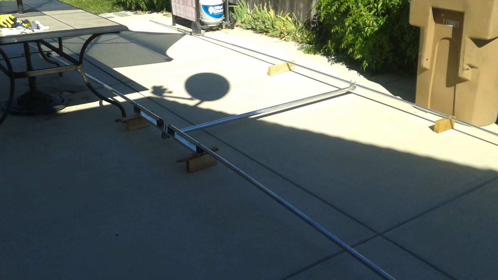
The next several photos show how I tested if the boom to mast bracket was perpendicular to the boom. I first made certain that the beam elements were in the same plane and then I installed a short section of mast that I had in the junk box. I then firmly affixed the boom bracket to the masts section and then moved the portion that attaches to the boom small increments so that a level placed on the mast section was "plumb" in two direction. Next I carefully tightened the U bolts which affix the adapter to the boom and we are there. Bob's your Uncle. We are really getting closer to B Day.
 
Pete N6QW


The second task was to "psych out" what was needed for the buying of the mast. The Radio Gods smiled down on me! It seems like I can use the wooden fence on three sides of my house as the guy anchor points for the mast. Luck Indeed! This test was just for the top most guys. I ran out of ti9me and will install the 2nd set tomorrow. Same anchor points.


Popular posts from this blog

January 26, 2024. A simple CW Transceiver/Transmitter

Cruise through the lower part of the ham bands bands and what do you hear? Well, FT-8 and CW. Often you will not hear any SSB stations yet go to the lower part of the bands, and it is a cacophony (I love that word) of bad sounding signals and some high-speed keying. Fast is not so much of the issue as is bad, run together and jerky keying. But none the less our hobby started there.    So, you could crank down your ICOM 7300 and watch the waterfall on CW or you could homebrew a radio. Actually, to do CW right you need more thought up front than you do with a SSB transceiver. Often, I will state that a CW Transceiver is much more difficult to build than a simple SSB rig. I published two articles in QRP Quarterly on CW transceivers and all I got was a yawn so maybe history will repeat itself.  Yawn!   30M CW Transceiver with RIT!   Of interest is that the LO is a Varactor tuned LC oscillator using a NE602. Look closely at the RIT circuit which is only activated on ...

March 31, 2024. Happy Easter to those who celebrate this day.

What a great day to Binge on Chocolate and experience the pain of that filling that has been leaking.  I would be in that category with the leaking filling(s) had I not just spent an amount equivalent to one of the fancy new uptown appliance box transceivers on two filling repairs. Well at least I can binge on the Chocolate bunnies without fear of pain. Regrettably everything appears to have jumped in price including the price of parts. Well not so much the parts as the shipping costs.  That notably is seen in the eBay treasures. I spotted a nice heathkit DX-20 for about $50 and the shipping was $65. Likely it is a twofer with part being a way to in effect charge a higher price by inflating the shipping and in part by increased shipping costs. Shipping with insurance across the US was about $150 for this jewel and that was three years ago. 6AM on the Left Coast ~ 20M Easter Sunday! My only hope is the cost of Chocolate Bunnies remains steady although a pound of See's Candies f...

August 30, 2024. A PNP 20M SSB Transceiver

Shown below is the Block Diagram for the 20M PNP SSB Transceiver steered in the  Transmit Mode . The components shown in the dotted block are relay steered so that the block module is single pass and amplifies in a single direction. The Block diagram show steered in Transmit.  Essentially the steering process works so that the IF Module input follows the Balanced Modulator on Transmit and then the input side follows the Receive Mixer on Receive. All done with some relays and a bit of RG174U coax. For those who count things in detail, this block diagram is not unlike what was used for the PSSST Transceiver which can be found on my website . Yes, a warmed over P3ST only using PNP devices. TYGNYBNT. 73's Pete N6QW