Back to the Nu-Rig
6/08/2016 ~ An Alternate LO/BFO/Display Systems for the Nu-Rig
While there has been a lot of interest and actual implementation in the 128X128 Color TFT worldwide, there are still those hams who want to use a simple 16x2 Backlit LCD for this project. So we did just that and see the photos below. I should confess once again of simply robbing the Let's Build Something original prototype of the parts and so the actual build time was pretty minimal. The Arduino is the Pro-Mini and the board is the Si5351. Not as fancy as the TFT but still serviceable. If any one would like the sketch contact me at n6qwham@gmail.com
73's
Pete N6QW


6/04/2016 ~ Revisiting the ZIA 20 Meter SSB Transceiver.
In mid-2015 I built the ZIA transceiver which featured Termination Insensitive Amplifiers developed by Wes Hayward and Bob Kopski. Unsatisfied with simply dubbing it the TIA, I decided to call it the ZIA where Z is Impedance thus Impedance Insensitive Amplifiers. The build was successful and embodied the NOKIA black and white display. This was a huge mistake as the display was flaky and very hard to read.
I made an error when I built the Nu-Rig as I made the panel cutout too large for the 128X128 TFT but this was quickly remedied as I had a 160X128 TFT which fit the hole perfectly. This left me with a spare 128X128 TFT. Consistent with my caregiver duties I have very few large blocks of time to build things. At best I can find 15 or 20 minutes so a retrofit of the ZIA had to be done in short blocks of time.
The retrofit involved removing the Nokia, adapting some code I had and rewiring a couple of the Arduino pins. I also had to make an adapter plate as the 128X128 TFT is physically smaller than the Nokia. So over a period of a couple of days I was able to get that done. During the course of "noodling" over the project I decided to continue with the blue theme --so about 20 minutes to paint the front and side panels. The last photo shows the ZIA before the paint job. I like the blue front panel versus the black panel.
73's
Pete N6QW


6/03/2016 ~ Some Updated Photos of the Nu-Rig.
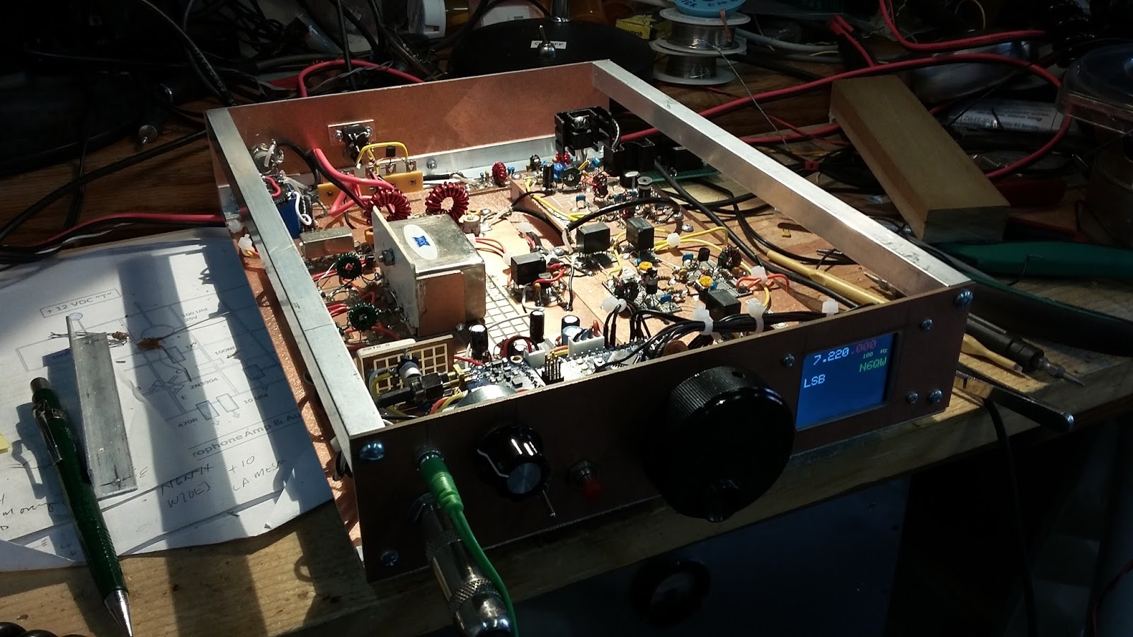
The following photos display the latest configuration of the rig plus some close-ups of the individual circuit boards. Again this is not a BITX so the circuits will not look the same as the classic design from Farhan.
The 1st photo shows the connections at the back panel including the ferrite beads on the entry DC power and the speaker jack.

Next is a close up of the 2N3904/2N3906 Bilateral amplifiers an original design from Plessey and found in EMRFD. I have created a SMD template for the amps and simply have the CNC Mill do all of the hard work. I am matching from 50 Ohms to 500 Ohms the impedance of the Yaseu XF-32A filter. Using a toroid type (FT-37-43 core) I used a single winding that gives the 10:1 match. A 19 turn winding using #26 wire tapped at 6 turns provides the match (19^2 = 361 and 6^2 = 36 361/36 = 10). Either side of course are the SBL-1's DBM's.

Moving on we next have a bidirectional amp that is an original design from N6QW (me). This stage features two single 2N3904 amplifiers that are gain adjustable. On the Rx side this provides the receiver RF amplifier and on Tx the other half provides the transmit pre-driver. The design is such that the amplifiers feed a 50 Ohm load comprised of a 100 Ohm fixed resistor in parallel with a 100 Ohm trimpot. The center wiper sample the output so that the level to the next stage is adjusted without destroying the 50 Ohm constant load. The signal relays provide the signal path switching.

Following the bi-directional stage is the driver and final stage. The driver is from EMRFD and uses the standard 2N3904 driving a 2N3866. the Final is an IRF510. The IRF510 is a pretty common circuit however I did add a 220 UFD bypass cap at the junction of the RF choke and the matching transformer connected to the Drain lead. This is in addition to a standard 100 NF. I found this cap enables bypassing at all frequencies and has cured some instability problems with the IRF510 I first discovered in the miniature version of the LBS project. Now it is a standard inclusion. Its presence is pretty obvious in the shot below. Note also the homebrew "bigger" heat sink on the IRF510. It is two heat sink that have been doubled up. "Mo betta!"

No homebrew rig would not be complete without a showing of the Arduino and the Si5351 and we have that next. This board sits right behind the front panel. Sitting right behind this assembly is the SMD microphone amp (upper left) and next to it is the audio amp stage (2N3904/LM386).


I continue to be amazed at the performance. As a final note the base plate is a piece of copper PC Board and all of the boards are elevated using aluminum pillars --so we have a really great common ground.
Thanks for riding along!
73's
Pete N6QW
6/2/2016 ~ More Refinements.
I continue to marvel at how well this rig is working. To that end I have looked at adding some things that I only consider doing when I want to keep a rig (like the KWM-4). I now have added some ferrite filters on the power input and replaced the 5 foot of power cord hardwired into the radio with a real panel mounted power connector. I also added a speaker jack on the back panel and this line also had a ferrite bead installed to prevent any RF feedback since the speaker jack is in close proximity to the BNC RF connector. These are not so much as to cure any short coming but more of good design practice.
To date I have had over 100 QSO's with the radio -- with about 1/2 of those running only 10 watts. It is a shame others don't take up the iron and roll their own. Even though it has digital generation of the LO and BFO as well as a color display --it is all homebrew including the case! There have been some comments that since it does not have an LC VFO or VXO it is not true homebrew or that there is no real satisfaction in writing lines of code. Well I can only say -- I get no negative comments from the 40M Spectral Purity Police about not being on frequency or having a drift to my signal!
73's
Pete N6QW
5/31/2016 ~ Some Refinements and Performance Observations.
I have been continuously making improvements and refinements to the Nu-Rig and thought I would share those.
The original version used a surplus crystal filter from an early Yaesu FT-101 designated the model XF-30A with a center frequency of 3.180 KHz. I had a later filter from the FT-101 series called the XF-32A. The pin outs, impedance and pin spacing are identical but the XF-32A is a slightly larger case. I believe the XF-32A to be a better filter and perhaps an 8 pole whereas I suspect that the XF-30A to be a six pole. The received signals appear to have less spill over with the latter unit. That is now installed in the rig.
I am seeing a significant power output with the IRF510 like about 10 watts (at 7 MHz) and decided that the heatsink originally used was on the marginal side. Read: when you touched it --you got a finger burn. With a larger sink now installed --it is hot but not to the point of burning ones finger. So that was a good move.
It was noted that there was a bit of intermittent operation of the microphone amp as evidenced by moving the vertical board (which was soldered to the main board) a bit and no output. Well a bit of head scratching (noodling) and removal of the board revealed a cold solder joint on one of the very small resistors. It was really hard to find. After fixing that cold joint and reinstalling the board --all is well.
I am able to hear DX from afar like ZS6 (South Africa) using only my marginal droopy dipole. The rig is capable of surprising sensitivity and now I should follow my own advice and work a bit more on the antenna. It follows that the antenna is now the weak link in the chain. I should note that running only 10 watts I have worked Utah, New Mexico, Nevada, Oregon and of course lots of California stations. At ten watts, QSO's with stations out to 600 mile range are typically what can be expected. Using my SB-200 I get about 180 Watts which has netted me coast to coast contacts.
The rig employs the Si5351 for the main frequency generation and the BFO signals. I have received two comments from stations in the Midwest, after revealing that it was a homebrew transceiver "Gee you are right on frequency and your signal doesn't drift as you might expect from a homebrew rig". Well folks it may be homebrew but it does have some very modern technology. The two must be part of the Spectral Purity Police which lurk on 40 Meters. Were I using an LC VFO then I suspect they would have been all over me about drifting 30 hertz.
The Nu-Rig has many standard building blocks that I have used in many of my projects --they work so why not? Again this is not a BITX in the classical sense; but does use bilateral and bi-directional circuitry some of which has been lifted from EMRFD and some is my own design. The point I am making is that it is not a complex design and should be easily replicated.
There is a caution -- it is a single conversion design and with the Yaesu filter at 3.180 MHz I would be loath to shift to other bands above 40 Meters. That said using other filter frequencies such as a 9.0 MHz filter then that concern would disappear. Now in a design such as my KWM-4 which is dual conversion, the Yaesu filter with the Si5351 would really shine. The FT-101 after all was multiple conversion transceiver. The point I am making is that care and forethought must be employed when developing the transceiver architecture and the choice of IF.
73's
Pete N6QW
5/26/2016 ~ The Front Panel has been painted --Oasis Blue
In the third photo you can see where I pressed the RED Tune Button and the word TUNE appears on the screen. There is code in the Arduino sketch that generates a 988 Hz tone (Square Wave which is smoothed with an RC Filter) which is fed into the SBL-1 DBM. With that code a small relay on the Arduino board is engaged to trip the PTT. So now we have a tune capability to adjust tuners or linear amps.
The next step is to finalize the remainder of the case which will be painted flat black.
73's
Pete N6QW


Some of the final assembly photos are shown below and this completes most of the mechanical assembly. The front panel will be painted --I am thinking light blue. I have had it on the air in its current state and barefoot it works FB -- am having a feedback problem when I add the SB-200. So I will be busy chasing that down.
[5/25/2016 -- Found the source of the feedback problem --a loose coaxial connector going into the SWR bridge. It was intermittent -- on low power it was not so big of a problem. But that is one that can bite you. I will continue to monitor; but several subsequent on the air reports with the amp said it was clean.]
[5/25/2016 -- Found the source of the feedback problem --a loose coaxial connector going into the SWR bridge. It was intermittent -- on low power it was not so big of a problem. But that is one that can bite you. I will continue to monitor; but several subsequent on the air reports with the amp said it was clean.]


Today we completed most of the mechanical work and the only item remaining is the RC Filter to turn the Square Waves generated in the Arduino Nano into Sine Waves for the tune signal. We have had it on the air in the current box and you always worry that even though it worked on the bench there is always a danger it won't work in the box.
This rig has a lot of soul as some of the boards were used in the 30M CW transceiver project which appeared in QRP Quarterly and then moved over to the LBS on the bread board (also in QRP Quarterly) and now this radio. The main tuning knob was purchased in St Louis some 20 years ago and now is now controlling the encoder.
Just in case you are wondering, this is not a BITX design but does use bilateral amplifiers originally designed by Plessey. The driver stage is from EMRFD and the intermediate bi-directional amp is my own design as is the 40M Band Pass Filter and the microphone amp. The Low Pass Filter is from W3NQN.
Just in case you forgot --- this is how it started


