Transceiver Architecture 2.16
5/21/2017
I am now documenting the LM373 build on my website so see the
following LM373 Link So for those tired of seeing me gush over my vintage 1970's designed, new rig you will have some relief. Have made about 2 dozen contacts including some at 600 watts. You got to have power to make lots of contacts so get over that QRP stuff! Soon we will be back to the crystal filter build on the DifX.
73's
Pete N6QW
5/19/2017 ~ QSL Card from the 1st contact with the LM373 Transceiver. Here is proof! Also noteworthy I was running only 15 Watts and the Mosley 2 Element Beam. What fun! I am now up to 10 Contacts with the LM373 Rig.
Pete N6QW

5/17/2016 Some added photos of the innards of the LM373 rig. We have now made six contacts with the new rig. I still need to tidy up the wiring. Yes, I succumbed to an IRF510 in the output which is not my favorite RF device --but it was an expedient. I am redeploying the K5BCQ 5 Watt final to the DifX dual conversion rig. With the outboard amp this will now do in excess of 100 Watts -- more than QRP!!!!! In the last photo you can see the LM373 IC square in the middle of the photo. All that work being done with one IC. To the aide and aft of the 9.0 MHz crystal filter is the 11 VDC power supply and the N6QW solid state power switch. The relay on the back panel only switches the antenna between T and R and one extra set of contacts switches in the outboard amp. In addition to the final wiring clean up I will add some aluminum support structure so that the front/back panels are rigid. This rig has taken about six weeks to build with some of that time awaiting the new Rigol scope.
Pete N6QW


5/16/2017
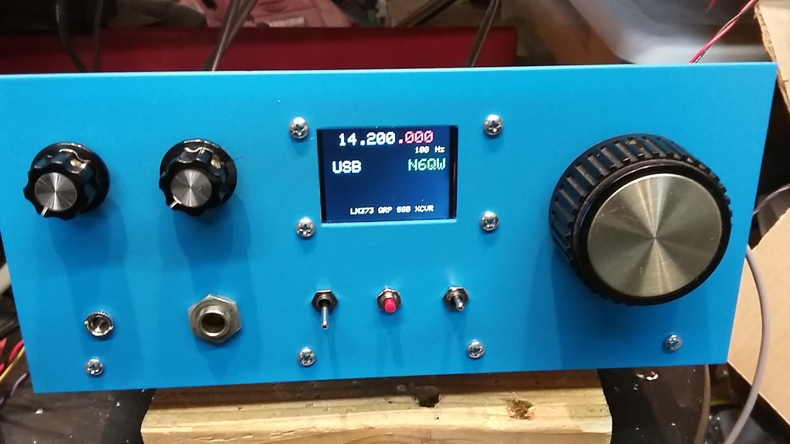
While I gather up some high quality capacitors to build the six pole 11.5 MHz Crystal Filter, I wanted to share more exciting news about the new LM373 20 Meter SSB Transceiver. Yes that is a photo on the masthead --Pretty Cool Blue isn't it?
This transceiver is more than a one hit wonder as I now have made three contacts with the new rig and I am please at how it works. It is also important to note that it is not a bilateral approach and thus truly not a Bitx! By that I mean that signals pass through the IF stage (which is a single IC -- the LM373) and steering through the single direction stage is done with 1N914 signal diodes. On receive the receiver mixer stage (SBL-1) is connected to the front end and the BFO is injected into one port of the LM373. On transmit the output from another SBL-1 acting as the balanced modulator is fed into the front end and now the LO is introduced into the port where formerly we injected the BFO. The port where the audio is recovered on receive is now the transmit output stage. Thus three ports on the LM373 are switched in going from Receive to Transmit --all in a single 14 Pin Dip package!
As I often saw with analog VFO's and BFO's the transition from R to T frequently caused a shift in frequency because of the loading effect as the LO and BFO were shifted to other parts of the circuits. That is not the case with the Si5351 --there is no shift. This single pass through an IF stage in older designs employing Analog LO/BFO's was problematic in this aspect. I wrestled with this issue and had some elaborate schemes to mitigate the problem. The bilateral approach where the LO and BFO were not shifted was a solution. Now with the Si5351 this is a solution with a single pass approach.
I have challenged myself to use as much stuff as I have in the junk box without resorting to placing orders for parts and that has been very rewarding in that "you use what you have!"
Beyond the LM373 I am using my standard Audio Amp stage as well as the bidirectional 2N3904 amp stage and the driver with the 2N2222 and BD139 produces a whopping 400 MW. I now will add the 5 watt K5BCQ RF Power MOSFET board that uses the Mitsubishi RDD series of transistors. Right now the 400 MW is driving an outboard SS amp all the way to about 15 Watts output.
The new Rigol DSO has been very useful as I worked on peaking a tweaking this new rig.
73's
Pete N6QW


