SDR #2 ~ Some Details and Info ~ The Lockdown Special!
August 5, 2020 ~A Tale of Two VNA Software Packages
I am certain there are those out there using the Nano VNA who will ask what is he talking about? At issue, if the software is not user friendly then it was written for a developer and not the user. Guy, I am only asking what time it is and not how to 3D print a watch. So for this tool to be useful then it must be user friendly.
A fellow ham put me on to another Nano VNA variant and I am supposing he is suggesting the use of training wheels as this program will even run under Windows XP. The program is called Nano VNA MOD (not exactly the title but close). The fact there is such a program suggests that Nano VNA Saver must be ...
So taking my two section 40M BPF I plotted the response in both the MOD and the Saver variants. At no time did I change anything on the hardware but only called up the software programs. Here are the two plots.
This is the MOD plot and the plus factors is a lot less buttons to push, IT DIDN'T CRASH, and the display is really nice for us OT's with eyesight issues. I was able to make small adjustments to the trimmers and immediately replot the changes. I ran this software first.

Next I ran (without touching anything on the hardware) the VNA Saver. Lucky me it did not crash!

I see you squinting ... (VNA Saver followed by MOD)

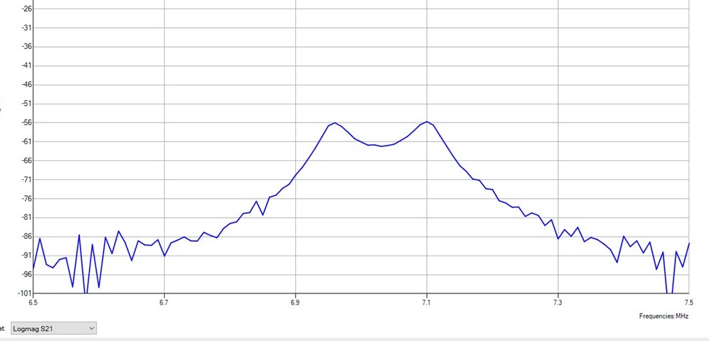
Without doing a rigorous analysis I would say that both software packages yield the same or very similar results. It does appear that if all you want is some verification of "what it is, is what it is" then the MOD version seems FB as a user.
I suspect if you only do 3d Order Linear Integration in the course of your normal day job, then you would resort to the Saver variant.
Sunspots are up! Thusly yesterday I made the LPF on the Lockdown Special so the LPF's are a simple plug in with RCA connectors.

158,000 deaths and nearing 5M infections from the Trump Virus and all the emperor (with a small e) can say: "It is what it is!" Perhaps as reader's of this blog you know someone in those two groups and are you OK with that callous pronouncement?
73's
Pete N6QW
August 4, 2020 More Nano VNA
Just a note here it seems like there will now be a shift to a new form of blog input from Blogger come August 24. The sample shown this morning showed composing in HTML versus plain text. If that is the the only option, then this blog is dead after that time. Why do those software weenies do things like this? This must be a preview of voter suppression for November 3rd.
Well I drug out the Nano VNA this morning to investigate the two section BPF that was originally used with the Lockdown Special. Sure shows it is kind of narrow with perhaps only 60 to 70 kHz of coverage around the center frequency. What was cool was that you could adjust the five trimmers and thereby visually see the impact of the changes.
BUT first the software, Nano VNA Saver, only crashed three times today. Additionally I have been informed that this is the premier suite for the Nano VNA. Well you could have fooled me. But 3 is better than the 10 times yesterday. This tool needs some help!

Above is the plot for the two section and you are able to place markers on the plot for references purpose. I eyeballed the 3 dB points and you get an automatic readout of the frequency based upon where you place the marker. So that is nice. But this BPF is too narrow for the whole band.
I suppose if you shifted the center frequency to 7.190 MHz you would get from 7.160 to 7.220 MHz which is where I mostly operate. BUT the negative for this filter is that FT-8 (7.074 MHz) is 10 dB down in receiving and transmitting. So from now on I will build the variant using the three section with the trimmer caps.

The Two Section BPF
Just discovered that the 3 dB Bandwidth analysis can be done automatically --amazing what you can do by button pushing. Now I no longer have to eyeball things. Good show Pete

If you have a Nano VNA and would like to share your use experience, drop me an email to the address on the masthead. Perhaps my use experience is an outlier; but I will only know if you let me know. Crashing as it does seems an abberation; but maybe that is just SOP. I hope it is something more than a cute toy.
73's
Pete N6QW
August 3, 2020 ~ Nano VNA Plots.


I am about to share some information where I am a Novice at working with this tool. So my data interpretation must be considered as somewhat guarded.
Recently a friend presented me with the Nano VNA (Vector Network Analyzer) which is a palm sized, feature rich and truly amazing piece of technology. Measurements with this tool let you literally dissect antenna performance, check networks and look inside those Band Pass Filters. This device will definitively tell you just how good the antenna or network is in Hardware! As with all paper (or computer simulations), the results are ideal and assumes perfect close tolerance components. The real world build can be light years away from the ideal. All this for somewhere between $50 and $100.
Having used it I am a little disappointed with the Nano VNA tester as the software program keeps crashing. If you don't mind keep restarting the program or have it stall right in the middle of a test then I guess you would accept these shortcomings. I simply don't!
Using the machine stand alone, it is too small and the drill down menu's are clunky. I want to test networks not adjust equalizer gain settings in an ICOM 7300! Perhaps others have had a similar experience. A Muntz TV was cheap; but you also had to put up with marginal performance.
While the unit can be used stand alone, the touch screen drill down menu system is "clunky" and incompatible with my FFS (Fat Finger Syndrome). Thankfully there is software that can be loaded on you computer, that lets you control the small VNA box via a USB connection. You hook up the Nano VNA to the DUT (Device Under Test) and then via USB and the GUI (Graphical User Interface) you can manipulate parameters and look at data points with the standard Mouse and keyboard.
I removed one turn from each of the coils and that shifted the curve upward by the right amount. Now I did find that by pinching, squeezing and compressing the turns, the shape of the curve would change. So this makes a really good case for windings that are evenly spaced around the toroid. Care is the operative word. I can also see the Return Loss is not plotted. So I don't know what that means. I have found the program to keep failing and closing down. This box may not really be ready for prime time. The CW portion once again is markedly different than the SSB portion -- the green marker is about 7.000 MHz and where it drops down to -70 dB is the start of the SSB portion of the band. So yes probably a good BPF but I do not like that it cannot be fine tuned. So the next mod might be to add some NPO trimmer caps with smaller fixed caps and then you could tune the filter. Three trimmers would like make a big difference.

Revised 40m BPF with one less turn.
Here we are with the 100PF Series cap replace with a 68PF and a 50PF Trimmer. The peaks can be brought in line and I think the dip in the Middle is a termination issue. I also found that I could peak the trimmer on 7.2 MHz and that gives you an ability to set the mid-band performance


The Photo Above is with the changed inductors and the 100PF replaced with a 68PF + 50PF Trimmer. Final tweaking and perky b--b twisting was done at 7.2 MHz where I TFMS.


The Photo Above is with the changed inductors and the 100PF replaced with a 68PF + 50PF Trimmer. Final tweaking and perky b--b twisting was done at 7.2 MHz where I TFMS.
******
My first foray with my Nano VNA was to measure the two Band Pass Filters that were constructed for the Lockdown Special. Several things are evident with my two Networks. I am in the ball park; but not necessarily the right section and row. Both filters need some peaking, tweaking and perky boob twisting. (This last is to check if you really read this blog in detail.)
The first shown below is the 20 Meter filter and the Gain Plot looks OK but the return loss has some bumps and humps.
The second is the 40 Meter and I need to rerun that as I think it looks a bit narrow.
The important thing is the Nano VNA is a powerful tool to give answers. But the real problem is how to correct what you see.


Below is a plot of the second 40M run and it affirms what I heard. Yesterday it seemed like the signals in the CW portion of the 40M Band were louder than around 7.2 MHz and the gain plot affirms that observance. It really drops off right below 7.2 MHz and that is the starting place for correction. I will remove 0ne turn from each of the coils and re-run the plot. Gee is the mystery solved? I think the gain plot is wide enough it just needs to be shifted upward in frequency. I am not going to cut the coils but simply remove one turn and reconnect.

We live in the Golden Era of Homebrew construction.
Had the Lockdown Special running just the IRF510 (@ 5 Watts) today and here are the results for Transmitting. The South Pole and Australia. Not too Shabbie (that is French for Shabby)!

In case you haven't been watching the latest pathetic Covid19 response from the emperor's (small e) administration, those of you in Rural America are now at high risk. On the air (40M) reports from these areas previously has always been --it won't happen here as we are not NYC (New York City).
Well Brothers and Sisters it is now there! Wear a Mask, Social Distance, Wash Your Hands Frequently, and Avoid Crowds! BTW Fox News is not your best friend! Unless you do these simple steps you will catch the Trump Virus!
73's
Pete N6QW
August 2, 2020 ~ Lockdown Special 20M Band Pass Filter Information.
The Band Pass Filter Board ... It works!

The Band Pass Filter Board ... It works!

Today I finished the 20 Meter Three Section Band Pass Filter and so am presenting the design for that band. Mind you I just took the 40 Meter Bitx filter and scaled it to 20 Meters (and 80 Meters) so this is not an original design. But I have verified the design in LT Spice --it is as good as Gold.


Note IUWHI, I found I was short on T-37-6 cores (only one in the bin) so I used the T-50-6 which results in 2.5 Uhy with 25 Turns of #26. The curve for this plot gives essentially the same flat response and the range is about 2 MHz centered on 14 MHz. So you can sub the cores and keep all other values the exact same!
The data for the 40Meter BPF was posted earlier and the 20 Meter Filter will be built on the same board as 40M one using the SMA connectors.
My friend N2CQR tells me there are Sun Spots being seen (like 20) and so things may be perking up on 20 Meters. Thus the move to build the 20M BPF. I already have a 20M LPF so a pretty easy hop for me.
73's
Pete N6QW
August 1, 2020 ~ More Lockdown Special Basics! Eight Boards Covered.
Following our extensive post from yesterday we are now looking at eight more of the modules on our Block Diagram. These modules include the Main SDR Board and the Bi-directional Board.


The photo of the labeled board is as of about a week ago and the lower photo has one major change and that is the board mounted SMA connector for the In/Out of the Splitter/Combiner Transformer. The more rigid connection is to address the fact that the board following this is the Band Pass Filter which is also fitted with SMA Connectors versus my original thought of a two pin header. Let's face it a two pin header works well if there is an infrequent push on, pull off. But repeated use makes for flaky connections. The SMA provides a more bullet proof approach.
Next is the Bi-Directional amp stage where yesterday I cut off a piece of the PC Board. My first "look see" was to have space on the board for plug in BPF's. Now with the BPF as a separate board the additional area was redundant.
Luckily I have a manual mill and simply milled off the extra area. The two relays steer the signal path depending upon whether it is being used in transmit or receive. The schematic description and layout for this board were discussed in an earlier post. This same board less the relays and one resistor change is used as the Driver board. This makes life simple.
The difference between the two boards was the Emitter resistor which is bypassed with a 10nF cap. In the Bi-Di board it was 22 Ohms. Change that to 50 Ohms. This circuit is "ON" all of the time and the 50 Ohm changes the operating point so that the tranny runs much cooler with only a slight change in gain. The Driver Emitter resistor is 4.7 Ohms. But since it is only on intermittently -- the added heat is OK. BOTH need heatsinks!

Next we will address the Driver and the IRF510 Board. To shorten connections between the two boards, I simply mounted the two boards on the metal plate that is used as the heat sink for the IRF51o. The Driver Board is the same as the Bi-Di board only the Emitter resistor is 4.7 Ohms. That resistor will make this circuit run like a perky set of boobs --sure makes it stick out!

The Yellow wire is from the +12 VDC Buss that is triggered by the I2C so that it powers the Driver board and at the same time provides "juice" to the IRF510 Bias circuit. The nice thing about having the LED in the loop-- you know that the Bias circuit is working. No LED no Bias!
Noteworthy is that power to the Drain of the IRF510 is always connected -- no hot switching here! But with no Bias applied and no signal there is no output! Also the LPF is always connected to the IRF510. In my final configuration I will like wise have SMA connectors between the LPF and the IRF510 Board.
In a subsequent posting I will list the values of the LPF components for two bands that are based on the W3NQN design.
So check off four more boards on the block diagram.

Next is the Band Pass Filter board with the SMA Connectors installed. A good source of these connectors is the several Si-5351 PLL Boards that I smoked. At $2.50 each --the connectors are worth more than the Si-5351. So Band switching will involve swapping four connections with two on the BPF and two on the LPF.

Finally the last item to be covered is the Sabrent Audio Dongle which is used for the Headset output and the Microphone input. Regrettably the dongle is too large for direct plug in to the SBC without interfering with other cables. So you need an extension cable with a USB Male at one end and a Female at the other end. then it is a simple matter to plug the Dongle into the cable and the other end into the USB port on the SBC.

Now I did mention about the Logitech headphone/headset that would plug into the USB direct without interference and internally contains the sound dongle.
But wait still another approach which I found out worked on the ASUS Tinker Board --just this morning. There is a combo 3.5 mm headphone / headset microphone jack right on the board and separate from the USB ports. I have an adapter so you can plug in the separate headset and microphone plugs and these are wired so you have a single RRTS (Ring Ring Tip Sleeve) connections on the output side. It works and that saves a USB Port as well as a sound dongle. The fidelity is communications quality but it works!
I have not verified this with the RPI3 -- so it may not be a universal solution. Watch this space. UPDATE: The RPi3 only brings out the audio output to the on board 3.5 mm Stereo jack. If you operate SSB you would need a microphone input port -- somewhere. So only the ASUS Tinker Board will enable eliminating the additional Sabrent Sound Dongle.
BTW the Tinker Board has more horsepower with a faster processor and a more Memory (2GB versus 1 GB). So you will see a difference. That said I have been unsuccessful in installing WSJTX on the Tinker Board. So if I can crack that nut, then we would suggest spending the additional $25 for the Tinker Board.

Above is the Optimal Shop Sound Card and the Rpi3.
As we noted the ASUS Tinker Board has both the Microphone Input and the Audio Output on this RRTS board mounted jack. Today's posting covered eight boards.
Only the USB Synthesizer / I2C boards have not been shown in photos -- the next posting will show those two boards.
Be safe, wear a mask, social distance and avoid crowds; but more importantly ignore any pronouncements from the emperor (with a small e)! Following his advice will likely mean, with a high degree of certainty, that you will catch the Trump Virus!
73's
Pete N6QW
July 31, 2020 ~ Lockdown Special Basics!
My Lockdown Special SDR Transceiver is working and I hope to make some SSB Contacts today. Actually the USB controller I am using has CW key inputs and of course QUISK has a full suite of CW functionalities. So those who have interests in CW you have not been excluded.
[Note I made two SSB Contacts and the reports were excellent--unsolicited was that audio had "presence" and sounded like a store bought radio! This evening I made five more contacts all with great signal reports. This radio is indeed a jewel in the crown.]
[Note I made two SSB Contacts and the reports were excellent--unsolicited was that audio had "presence" and sounded like a store bought radio! This evening I made five more contacts all with great signal reports. This radio is indeed a jewel in the crown.]
But in my rush to finish this jewel, I may have left some readers behind and that was not intentional. So now I am backing up to start from the beginning and a bit different in the sense that we have the value of a working transceiver versus "Hey lets try to build this and see if it works". It is working!
So let us start with a Block Diagram which is shown below.

I have purposely added some of the control circuit inputs (noted as I2C) since it may not be so obvious that connections are required aside from just the RF in/out. In general each of the blocks are just that, a block module.
While there are those who would decry that this is not one big circuit board. In the very course of this build, I had to make changes to various block modules such as the Band Pass Filter. The module approach made that less difficult than trying to work with a large circuit board.
Let us talk a bit about the I2C control. The QUISK software has certain dashboard buttons that are engaged with the mouse. These include a SPOT function, the PTT and finally VOX buttons. Engaging these buttons with the mouse sends a signal via USB to the Synthesizer/Controller board that provides+5 VDC to an output pin. I use this +5 VDC to transistor switch a power relay that controls a bank of four pins that all have +12 VDC on their pins; but only when one of the three buttons is operational. Here is what happens when the +12 VDC appears on the Buss (resulting from one of the three conditions and triggering the I2C pin)
- The DPDT Relay of the Main RADIG SDR Board switches the Modem ports from the Sound Card so that the LINE OUT is now connected to the Modem ports. Unenergized the LINE INUT ports from the Sound Card were connected to the two modems. Now I do another thing with this relay and that is to physically invert the I and Q channels on transmit by reversing the I and Q wiring on the 3.5 mm Stereo jack. I since have found a little (unknown to me) button in QUISK that will reverse the outputs on transmit. So you have a choice again either in Software (QUISK) or Hardware (Pete).
- The two relays on the bidirectional steering of the amp board which also uses the 2N2219 now routes the signals to/ from the Band Pass Filter to this board. Upon engagement the RF Output from the Band Pass Filter is passed to the Bi-Di amp and the output from this board is further processed in the RF amplifier stages (the other 2N2219A and the IRF510). On Receive (unenergized) the signals from the antenna are fed to the input side of this Bi-directional amp stage and the output is now fed to the Band Pass Filter and on to the Magic splitter/combiner on the RADIG Main board.
- Again upon being signaled from the I2C, +12 VDC is applied to the 2N2219A Driver board which is permanently connected to the IRF510 (or RD06HHF1).
- The Bias network in the IRF510 is only powered on, as evidenced by the glowing RED LED when +12 VDC is applied to the 78L05 from the 12 VDC Buss tripped by the I2C powered 2N3904 switching transistor to the relay
- Finally we have the TR Relay that is energized from the 12 VDC Buss. When power is applied to the T/R Relay (+12 VDC) I tap off that pin with a 10K resistor fed to the Base of a 2N3904 with the Collector connected to the center Pin of a RCA jack (linear amp switch) and the Emitter is grounded.
So if you have concluded as such -- the Single Board Computer (SBC) in the case of the RPi3 or Tinker Board is doing a lot of the heavy lifting.
Now lets cover a couple of the blocks that are simply devices plugged into the SBC. These are mainly Audio Devices and include the Optimal Shop USB 2.0 Sound Card and the Sabrent Dongle. Shop a lot for these devices. I found the same Sound Card by a different name on eBay for $4 cheaper ($12 versus $16). The specifications are the same and they look the same only a different case color. I think the less expensive one does not come with a USB to Mini cable nor a software disk. You can find a cable for about $1.20 and you don't need the software. The Sabrent Dongle was about $7 but I saw some similar units for about $3. The key is the Audio Processor so look in the specs for words like CM106 like processor. So the RPi3 can be found for $35 (even a RPi4 1GB is less at Adafruit) and the upshot is three blocks can be found for less than $50. An order out from McDonalds for three is about $50!
[Another option for the Sabrent dongle is what I call a Threefer!. I have Logitech headset microphone that I formerly used during the Soldersmoke podcasts. Bill, N2CQR noted there was some spill over from the headset to the microphone so I stopped using it. But there are three parts to that headset including the headset, the microphone and the USB plug which actually contains a built in sound card. So just insert the Logitech unit into the RPi3 or Tinker Board and have a Threefer! That makes for a very compact assembly!]
[Another option for the Sabrent dongle is what I call a Threefer!. I have Logitech headset microphone that I formerly used during the Soldersmoke podcasts. Bill, N2CQR noted there was some spill over from the headset to the microphone so I stopped using it. But there are three parts to that headset including the headset, the microphone and the USB plug which actually contains a built in sound card. So just insert the Logitech unit into the RPi3 or Tinker Board and have a Threefer! That makes for a very compact assembly!]
I am stopping here so you can catch your breath. I intend to cover all of the boards with photos of each of the individual boards. Watch this space.
73's
Pete N6QW
The Trump Virus is now 4.3+ Million infected and likely today 153,000 deaths. This is nuts, as the emperor (with a small e) demands your kids go back to school with no plan, no strategy nor resources to do it safely.
A big shout out to Gov. DeSantis in FL -- how is the no mask rule working out for you. You seem to be out of step with the mainstream. Hope you don't get recalled. Worse, you might get dumped by the emperor (with a miniscule e).
A big shout out to Gov. DeSantis in FL -- how is the no mask rule working out for you. You seem to be out of step with the mainstream. Hope you don't get recalled. Worse, you might get dumped by the emperor (with a miniscule e).
July 30, 2020 ~ Lockdown Special with some Refinements plus FT-8.
My Band Pass Filter alternate (for the QRP-Labs Filters I misordered) was too narrow, as it covered the SSB portion of the band FB; but if you wanted FT-8 the power output dropped off a cliff. So I changed that filter to a non-tunable but wider bandwidth filter lifted directly from the Bitx transceivers.
The replacement for the replacement is a 3 section and the Pout is more or less flat across 40M. While making this filter I decided to include 2 filters on a single board and to use the two pin header approach for the final build. I have scaled the 40M version for both 20 and 75 Meters. Thus I have some choices. The pads are 1/2 inch by 1/2 inch --- 7 of them.
The replacement for the replacement is a 3 section and the Pout is more or less flat across 40M. While making this filter I decided to include 2 filters on a single board and to use the two pin header approach for the final build. I have scaled the 40M version for both 20 and 75 Meters. Thus I have some choices. The pads are 1/2 inch by 1/2 inch --- 7 of them.

The whole BPF build took about 1 hour to fabricate including laying out the Circuit Board for my CNC Mill and finding the parts. There are three T-50-6 cores with a winding of 38 turns of #26, ( about 5.8 uHy) and there are seven total caps with three each 100 pF (light brown), two 470 pF (dark brown) and two 1000 pF caps (orange). Just follow the photo and you can build it.


Shortly after the filter install, I moved down to 7.074 MHz USB and observed the FT-8 activity. Running just the driver is only good for about 400 milliwatts. But with two amps following the driver I get a whopping 65 watts to the antenna. I did manage to make one FT-8 contact (at 65 watts). Thus, we have done WSPR, FT-8 and maybe later tonight some SSB contacts.

On deck (that is a Navy term) for tomorrow is the fabrication of the IRF510 amp stage but I will build it so that the stage could use either the IRF510 or the Mitsubishi RD06HHF1 RF FET. A simple Red LED added to the Bias circuit is all that is needed for either device. You must have an adequate heat sink (read stout and robust) for the RF FET --it draws a lot more idling current; but is better suited for higher frequency operation.


The finished IRF510 amp board. I get in excess of 5 watts out on 40M. So with all the linear amps in line we can do about 600 Watts on 40M. Now that should result in more FT-8 contacts.
This photo is real CRAP on the bench. I have purposefully distorted the photo since it looks pretty crude, dude!

Did some WSPR this morning with a specific look at my Delta beam antenna. I am suggesting it may have a pattern that looks like this.

This takes the cake: A prominent unnamed government official from the State of Texas who has contracted the Trump Virus suggests it was because he was forced to wear a mask. He is sure he will be cured since he is taking hydroxychloroquine.
There was no mention about drinking Lysol or forcing a "black light" up his butt. Hope his constituents feel comfortable with his representation since he seems to be out of step with the rest of the WORLD and the science.
What can I say -- other than he is from Texas and truly hopeful he will recover. Maybe someone from Texas has more info if Lysol and Black Light are being employed in the treatment regimen.
RIP Herman Cain -- Maybe wearing a mask at the Tulsa Rally
would have prevented this unfortunate death. Hey, unnamed government official from Texas are you listening? Oh, forgot the rapping noise from the pencil on the microphone makes it near impossible to hear anything.
73's
Pete N6QW
*****
July 29, 2020 ~ Lockdown Special is on the Air. Yes Virginia, in addition to there being a Santa Claus, the Lockdown Special does indeed work!
Running just the driver stage at 100 Milliwatts this morning I put the Lockdown Special on 40 Meter WSPR in transmit. It works! The best DX was AI6VN/KH6 out in Hawaii where I was spotted several times. The signal was also heard out to the East Coast. A couple of factors: 1) The band conditions were OK and the new Delta Loop antenna sure helped.
The next project module will be the IRF510 Final RF Amp stage so we get a bit more juice into the antenna. Last night the East Coast stations were really loud --almost like locals.
One station in particular station (a K1) was burning up my front end. He also was spouting effusive congratulatory claims about the emperor (with a small e) and what a terrific job he was doing on the Covid19 response. No mention was made of the 150,000 deaths nor the 4.3M infections. But he did say hydroxychloroquine was probably a miracle cure. I wonder what planet spawned this person?
So Governor DeSantis how does it feel to host the Trump Virus Epicenter? Be extra careful my friend, as your usefulness to the emperor (with a small e) may be in jeopardy! Just hope they don't recall you. I think you said you would never see a outbreak in FL as big as NY -- well good buddy, l0oks like you were wrong! If the math is correct you are > 10% of all of the US infections and 4% of the deaths. Wow, you sure have that under control.
To Louie from Texas -- that sure was a great idea not to wear a mask. We hope you recover; but think of the life lesson you just learned. Then again maybe not.
73's
Pete N6QW
| Local (y-m-d) | TX | txGrid | RX | rxGrid | MHz | W | SNR | drift | Km | Km/W | SpotQ |
|---|---|---|---|---|---|---|---|---|---|---|---|
| 2020-7-29 06:14 | N6QW | DM04md | N5XKG | DM65pg | 7.040122 | 0.1 | -26 | 0 | 1126 | 11260 | 3128 |
| 2020-7-29 06:14 | N6QW | DM04md | WA6OUR-K | CN87xo | 7.040073 | 0.1 | -20 | 0 | 1518 | 15180 | 6747 |
| 2020-7-29 06:14 | N6QW | DM04md | WA5NGP | EM10cn | 7.040175 | 0.1 | -19 | 0 | 2024 | 20240 | 9558 |
| 2020-7-29 06:14 | N6QW | DM04md | K5CGM | EM25ax | 7.040121 | 0.1 | -25 | 0 | 2098 | 20980 | 6411 |
| 2020-7-29 06:14 | N6QW | DM04md | KG5UWB | EM12jv | 7.040121 | 0.1 | -27 | 0 | 2017 | 20170 | 5043 |
| 2020-7-29 06:14 | N6QW | DM04md | KD7WPQ | DN18rh | 7.04013 | 0.1 | -28 | 0 | 1588 | 15880 | 3529 |
| 2020-7-29 06:14 | N6QW | DM04md | WB7ABP | CM88ok | 7.040118 | 0.1 | -26 | 0 | 588 | 5880 | 1633 |
| 2020-7-29 06:14 | N6QW | DM04md | N6GN/K | DN70ll | 7.040114 | 0.1 | -25 | 0 | 1416 | 14160 | 4327 |
| 2020-7-29 06:14 | N6QW | DM04md | KF7FBF | CN87uq | 7.040128 | 0.1 | -27 | 0 | 1531 | 15310 | 3828 |
| 2020-7-29 06:14 | N6QW | DM04md | KA7OEI-1 | DN31uo | 7.040118 | 0.1 | -20 | 0 | 1014 | 10140 | 4507 |
| 2020-7-29 06:14 | N6QW | DM04md | AI6VN/KH6 | BL10rx | 7.040118 | 0.1 | -22 | 0 | 3956 | 39560 | 15384 |
| 2020-7-29 06:14 | N6QW | DM04md | WO7I | DN10cw | 7.040118 | 0.1 | -28 | 0 | 762 | 7620 | 1693 |
| 2020-7-29 06:14 | N6QW | DM04md | KK6PR | CN94ik | 7.040114 | 0.1 | -24 | 0 | 1162 | 11620 | 3873 |
| 2020-7-29 06:14 | N6QW | DM04md | SWLDM63 | DM63jd | 7.040124 | 0.1 | -14 | 0 | 1093 | 10930 | 6679 |
| 2020-7-29 06:06 | N6QW | DM04md | NN6RF | CM87uw | 7.040039 | 0.1 | -20 | 0 | 517 | 5170 | 2298 |
| 2020-7-29 06:06 | N6QW | DM04md | AA7NM | CN86ox | 7.04014 | 0.1 | -25 | 0 | 1463 | 14630 | 4470 |
| 2020-7-29 06:06 | N6QW | DM04md | WA6OUR-K | CN87xo | 7.040074 | 0.1 | -24 | 0 | 1518 | 15180 | 5060 |
| 2020-7-29 06:06 | N6QW | DM04md | N5XKG | DM65pg | 7.040122 | 0.1 | -21 | 0 | 1126 | 11260 | 4692 |
| 2020-7-29 06:06 | N6QW | DM04md | W7OWO | CN85lh | 7.040123 | 0.1 | -18 | -2 | 1289 | 12890 | 6445 |
| 2020-7-29 06:06 | N6QW | DM04md | W5WTH | EM10bj | 7.040119 | 0.1 | -25 | 0 | 2022 | 20220 | 6178 |
| 2020-7-29 06:06 | N6QW | DM04md | KD7WPQ | DN18rh | 7.04013 | 0.1 | -22 | 0 | 1588 | 15880 | 6176 |
| 2020-7-29 06:06 | N6QW | DM04md | N6GN/K | DN70ll | 7.040114 | 0.1 | -20 | 0 | 1416 | 14160 | 6293 |
| 2020-7-29 06:06 | N6QW | DM04md | KA7OEI-1 | DN31uo | 7.040118 | 0.1 | -16 | 0 | 1014 | 10140 | 5633 |
| 2020-7-29 06:06 | N6QW | DM04md | AI6VN/KH6 | BL10rx | 7.040118 | 0.1 | -19 | 0 | 3956 | 39560 | 18681 |
| 2020-7-29 06:06 | N6QW | DM04md | KP4MD | CM98iq | 7.040118 | 0.1 | -25 | 0 | 546 | 5460 | 1668 |
| 2020-7-29 05:58 | N6QW | DM04md | AA7NM | CN86ox | 7.040173 | 0.1 | -26 | 0 | 1463 | 14630 | 4064 |
| 2020-7-29 05:58 | N6QW | DM04md | W7OWO | CN85lh | 7.040122 | 0.1 | -6 | 0 | 1289 | 12890 | 10742 |
| 2020-7-29 05:58 | N6QW | DM04md | WA5NGP | EM10cn | 7.040175 | 0.1 | -20 | 0 | 2024 | 20240 | 8996 |
| 2020-7-29 05:58 | N6QW | DM04md | WA6OUR-K | CN87xo | 7.040074 | 0.1 | -26 | 0 | 1518 | 15180 | 4217 |
| 2020-7-29 05:58 | N6QW | DM04md | KD7WPQ | DN18rh | 7.04013 | 0.1 | -25 | 0 | 1588 | 15880 | 4852 |
| 2020-7-29 05:58 | N6QW | DM04md | N5XKG | DM65pg | 7.040122 | 0.1 | -30 | 0 | 1126 | 11260 | 1877 |
| 2020-7-29 05:58 | N6QW | DM04md | W5WTH | EM10bj | 7.04012 | 0.1 | -25 | 0 | 2022 | 20220 | 6178 |
| 2020-7-29 05:58 | N6QW | DM04md | N6GN/K | DN70ll | 7.040114 | 0.1 | -19 | 0 | 1416 | 14160 | 6687 |
| 2020-7-29 05:58 | N6QW | DM04md | KA7OEI-1 | DN31uo | 7.040118 | 0.1 | -22 | 0 | 1014 | 10140 | 3943 |
| 2020-7-29 05:58 | N6QW | DM04md | WO7I | DN10cw | 7.040118 | 0.1 | -23 | 0 | 762 | 7620 | 2752 |
| 2020-7-29 05:58 | N6QW | DM04md | AI6VN/KH6 | BL10rx | 7.040118 | 0.1 | -22 | 0 | 3956 | 39560 | 15384 |
| 2020-7-29 05:58 | N6QW | DM04md | KP4MD | CM98iq | 7.040118 | 0.1 | -28 | 0 | 546 | 5460 | 1213 |
| 2020-7-29 05:58 | N6QW | DM04md | KK6PR | CN94ik | 7.040115 | 0.1 | -15 | 0 | 1162 | 11620 | 6778 |
| 2020-7-29 05:58 | N6QW | DM04md | SWLDM63 | DM63jd | 7.040124 | 0.1 | -23 | 0 | 1093 | 10930 | 3947 |
| 2020-7-29 05:50 | N6QW | DM04md | WA6OUR-K | CN87xo | 7.040074 | 0.1 | -31 | 0 | 1518 | 15180 | 2108 |
| 2020-7-29 05:50 | N6QW | DM04md | N5XKG | DM65pg | 7.040122 | 0.1 | -22 | 0 | 1126 | 11260 | 4379 |
| 2020-7-29 05:50 | N6QW | DM04md | WA5NGP | EM10cn | 7.040175 | 0.1 | -16 | 0 | 2024 | 20240 | 11244 |
| 2020-7-29 05:50 | N6QW | DM04md | KV0S | EM38tv | 7.040132 | 0.1 | -29 | 0 | 2424 | 24240 | 4713 |
| 2020-7-29 05:50 | N6QW | DM04md | WB7ABP | CM88ok | 7.040118 | 0.1 | -26 | 0 | 588 | 5880 | 1633 |
| 2020-7-29 05:50 | N6QW | DM04md | N6GN/K | DN70ll | 7.040114 | 0.1 | -20 | 0 | 1416 | 14160 | 6293 |
| 2020-7-29 05:50 | N6QW | DM04md | KA7OEI-1 | DN31uo | 7.040118 | 0.1 | -16 | 0 | 1014 | 10140 | 5633 |
| 2020-7-29 05:50 | N6QW | DM04md | AI6VN/KH6 | BL10rx | 7.040118 | 0.1 | -18 | 0 | 3956 | 39560 | 19780 |
| 2020-7-29 05:50 | N6QW | DM04md | WO7I | DN10cw | 7.040118 | 0.1 | -26 | 0 | 762 | 7620 | 2117 |
| 2020-7-29 05:50 | N6QW | DM04md | KK6PR | CN94ik | 7.040115 | 0.1 | -15 | 0 | 1162 | 11620 | 6778 |
| 2020-7-29 05:50 | N6QW | DM04md | KJ6MKI | CM88oi | 7.040116 | 0.1 | -17 | 0 | 580 | 5800 | 3061 |
| 2020-7-29 05:40 | N6QW | DM04md | AA7NM | CN86ox | 7.040173 | 0.1 | -24 | 0 | 1463 | 14630 | 4877 |
| 2020-7-29 05:40 | N6QW | DM04md | KD7WPQ | DN18rh | 7.04013 | 0.1 | -25 | 0 | 1588 | 15880 | 4852 |
| 2020-7-29 05:40 | N6QW | DM04md | WA5NGP | EM10cn | 7.040176 | 0.1 | -16 | 0 | 2024 | 20240 | 11244 |
| 2020-7-29 05:40 | N6QW | DM04md | W5WTH | EM10bj | 7.04012 | 0.1 | -27 | 0 | 2022 | 20220 | 5055 |
| 2020-7-29 05:40 | N6QW | DM04md | N5XKG | DM65pg | 7.040122 | 0.1 | -24 | 0 | 1126 | 11260 | 3753 |
| 2020-7-29 05:40 | N6QW | DM04md | N6GN/K | DN70ll | 7.040114 | 0.1 | -26 | 0 | 1416 | 14160 | 3933 |
| 2020-7-29 05:40 | N6QW | DM04md | KA7OEI-1 | DN31uo | 7.040118 | 0.1 | -18 | 0 | 1014 | 10140 | 5070 |
| 2020-7-29 05:40 | N6QW | DM04md | AI6VN/KH6 | BL10rx | 7.040118 | 0.1 | -19 | 0 | 3956 | 39560 | 18681 |
| 2020-7-29 05:40 | N6QW | DM04md | KK6PR | CN94ik | 7.040115 | 0.1 | -13 | 0 | 1162 | 11620 | 7424 |
| 2020-7-29 05:40 | N6QW | DM04md | SWLDM63 | DM63jd | 7.040125 | 0.1 | -14 | 0 | 1093 | 10930 | 6679 |
| 2020-7-29 05:40 | N6QW | DM04md | KA7OEI | DN40ao | 7.040119 | 0.1 | -2 | 0 | 947 | 9470 | 8944 |
| 2020-7-29 05:30 | N6QW | DM04md | KD7WPQ | DN18rh | 7.040131 | 0.1 | -25 | 0 | 1588 | 15880 | 4852 |
| 2020-7-29 05:30 | N6QW | DM04md | WA6OUR-K | CN87xo | 7.040075 | 0.1 | -29 | 0 | 1518 | 15180 | 2952 |
| 2020-7-29 05:30 | N6QW | DM04md | N5XKG | DM65pg | 7.040123 | 0.1 | -26 | 0 | 1126 | 11260 | 3128 |
| 2020-7-29 05:30 | N6QW | DM04md | KA7OEI-1 | DN31uo | 7.040118 | 0.1 | -18 | 0 | 1014 | 10140 | 5070 |
| 2020-7-29 05:30 | N6QW | DM04md | AI6VN/KH6 | BL10rx | 7.040118 | 0.1 | -18 | 0 | 3956 | 39560 | 19780 |
| 2020-7-29 05:30 | N6QW | DM04md | KK6PR | CN94ik | 7.040115 | 0.1 | -10 | 0 | 1162 | 11620 | 8392 |
| 2020-7-29 05:30 | N6QW | DM04md | WO7I | DN10cw | 7.04011 |
Just for comparison here are the received stations spotted -- so the Lockdown Special hears very well! So waht are you waiting for --start ordering parts!

July 28, 2020 ~ BPF & Driver Stage
Yesterday I worked on the driver stage and was so excited when the mail arrived and there was a box from QRP-Labs --the Band Pass Filters arrived! I tore open the box and admired the two small bags and then panic struck!
There were no trimmer caps and there were three toroids in the bag. Oops looks like I have purchased some very neat Low Pass Filters. Look closely on the bag and you will see the words LPF. I had planned on home brewing the LPF; but now I guess I can check that box. So back to the order page and this time get BPF's. But all is not lost


When you know stuff you can do stuff so I just redesigned my stock BPF design to use T-50-2 cores and did the LT Spice simulation. My main objective is to cover the SSB portion of the band so the filter is somewhat narrow.
Once again I am able to have essentially the same basic components ( 5 Trimmer Caps and two cores) and the only difference between 40M and 20M is two 150 PF Silver Mica Caps and retuning the trimmers for the band of choice. The cores are T-50-2 and a total of 21 Turns of #24 enamel wire (about 2.16 uHy), plus the two 150PF Caps for 40 Meters. The five trimmers are all 50PF available from Jameco Electronics. W8DIZ also sells the 50 PF trimmer caps and the Toroids. Ideally the T-68-2 cores have been used in my prior BPF's but I had none in the bins --so IUWIH. (I Used What I Had).


Now a brand new idea I had resulting from my ordering SNAFU, was to build the two filters (40 and 20M) on a small chunk of PC board with two pin headers at either end. Then the in/out coax (RG-174-U) would have a two pin plugs on each cable so that band changing is simply moving the cable onto a different header. You could even extend this concept to more than two bands -- you just need a bigger board. The "squares" in the photo are 1/2 inch by 1/2 inch for the smaller pads and 1/2 inch by 3/4 inch for the larger two. The pads do not have to be this big --but with my FFS (Fat Finger Syndrome) plenty of room for me to hold the components while soldering to the board.
I also built the driver stage which is the same basic design as the bi-directional amp stage with a change in the emitter resistor to 4.7 Ohms for the Driver. This boosts the stage gain and don't talk long --the tranny will be hot enough to burn you --so use a big heat sink! The Bi-Di stage uses a 22 Ohm -- still warm but is "on" all of the time acting as the Rx RF Amp on Receive and Tx Pre-Driver on Transmit. That is a real real Twofer!


Above is the PC Board Layout of the Bi-Di and Driver Board. For reference purposes the smaller squares are 1/4 inch by 1/4 inch. What is unique about this layout is that it minimizes the interconnect. Starting in the upper left corner a 1o Ohm resistor which goes from the lower square to the upper square. The lower one is the connect point for 12VT and the upper one is a junction of a 0.1 uFd, the 10 ohm and one end of the 5 Turn Choke wound on a FT-37-43 core. The other end of the choke connects to the middle vertical square that has five connections.
Connecting the top part of the Middle square to the upper most square on the right side is another 0.1ufd which is the output port. Once again connecting to the Middle square over the the second square on the right is a parallel combination of a 3.3K and another 0.1ufd capacitor. The final connection to the Middle pad is the Collector of the transistor. The horizontal square running across the board is the Base Connection. So going back the the right hand side where we had the parallel combo of the 3.3K and 0.1ufd we bridge from that connection to the Base connection with a 680 Ohm resistor. At the left side of the horizontal square we connect a 3.3K Ohm to Ground and one end of a 0.01ufd cap which is the input port. the other end of the 0.01ufd is connected to the small pad on the lower left side. The smaller pad to the right of the input port is the Emitter pad which has the transistor Emitter connect point along with either a 22 Ohm (Bi-Di) or 4.7 Ohm (Driver) along with a parallel combo of a 0.01ufd Emitter Bypass Cap to boost the AC stage gain.
A couple of points: Compact, Direct connection to Pads and Physical Separation of the In's/Out's. Another key point is the RF transistor is keyed so the EBC nicely matches the pads --no matter if they are reversed or not. Also there is plenty of room for a large sized heatsink. When you know stuff you can do stuff!
Using just two transistors (Pre-Driver and Driver) following the mainboard, the output measures 10 volts PTP into 50 Ohms and so if you do the math 10^2 = 100 and times 2.5 equals 250 MW. The 2.5 is a factor to convert to RMS with a load of 50 Ohms.
You are welcome to check this by doing the math yourself! That will nicely drive an IRF510 to several watts of RF --even on 20 Meters! In the photo above you can see my 50 Ohm load (two 100 Ohms 1/4 watt resistors in parallel).
Just think despite extra-ordinary pre-cautions, Major League Baseball has been infected with Covid19. Yet, the emperor (with a diminished e) wants your kids back in school with no plan, strategy or resources to make that happen safely. This is an abject failure of leadership! So Governor DeSantis it is amazing what two months can do to your victory lap.
73's
Pete, N6QW
July 27, 2020 ~ The Software
(There were a couple of typos in the "usb" instructions in an earlier version of this posting. They are now correct. I can only offer the excuse of being a two finger typist and am subject to advancing age. Thanks Phil for catching this!)
I have been "dabbling" with SDR radios for over 10 years and have used several different SDR software forms. My journey started the Soft Rock V6.2 Transceiver and the modified FLEX Radio Power SDR. Several years ago I used HDSDR and now for about the last four years QUISK.
These are not all of the possible software suites that could be used with the RADIG! But of the ones I have tried QUISK wins hands down! In the case of Power SDR and the HDSDR you had to install additional software called VAC and it was not free! You had to send money ($30) to Russia so that you could connect the audio devices to Power SDR and HDSDR.
Quisk is free and needs no other software unless you want to do WSPR and FT-8; but that is free. [Once wsjtx is downloaded --it can be installed right from the File Manger with the RPi or Linux Mint. I have not been able to successfully install wsjtx on the Tinker Board as the process is quite complex and I got easily lost. The other two computers you simply right click on the file in the Download file and select install --boom you are there.]
I strongly recommend and endorse the use of quisk from N2ADR. You can get quisk from https://pypi.org/project/quisk. There are several forms for the Quisk download including Windows and Linux.
I have never successfully had it work in the Windows variants! Yet the Linux version has worked flawlessly with the Raspberry Pi, ASUS Tinker Board and even an old HP Desktop converted to Linux Mint. You should also visit the N2ADR Quisk site to get the installation instructions.
Interestingly the original Quisk was written for Python 2.7 and since 2020 Python 3.0 is now the Python of choice. N2ADR has updated Quisk for the Python 3.0; but also has the files for 2.7. Both can be installed on the same computer and there are no interaction problems.
Once you have the basic OS installed on your machine to operate the Pi, Tinker Board or MINT Cinnamon 20 then you need to start the download of Quisk.
In all cases for the Linux, the downloaded file appears in the File Manager in the Download file. Open the File Manager and create a new folder called quisk and a new empty file called .quisk_conf.py don't forget the period in front of the quisk.
In the earlier versions of Quisk this empty file contained customizations that when Quisk booted up it searched this file for those customizations. I typically left it blank. The basic software on boot up went to that file and looked for any special instructions. If there were none it moved on. But if you failed to include the file, the software would give you an error message. I think N2ADR says that file is no longer needed. But it is like the girl who tells you she is safe; but you don't believe her and add a bit of protection!
The next step is to extract the quisk downloaded file into quisk folder.
Now for the software installation and the first thing I do is to provide routing instructions for the "usb" interface. Open a terminal and then type in
sudo nano /etc/udev/rules.d/local.rules
You will be taken to a new page and enter this exactly (check it several times)
SUBSYSTEM=="usb",ATTR{idVendor}=="16c0",ATTR{idProduct}=="05dc",MODE="0666",GROUP="dialout"
When done and after checking for all the commas and punctuation, then hit
Crtl X, Shift Y and Enter. Then reboot.
Later on when you open up Quisk, you will find these two entries in the Quisk menus. Amazing how that works.
After reboot open a terminal and install the files from the N2ADR instructions short of those that build and launch the Quisk set up. BUT add one more after the sudo apt-get install python3-pip and that is as follows
sudo apt-get install pavucontrol
This last entry installs the Pulse Audio Control Panel so you can adjust the I and Q levels as well as Microphone Gain and expand the available audio output.
Likely it will not go well the first time you try this --but hang in there and if you check http://www.n6qwradiogenius.us there is more info on loading Quisk.
Now a really nice feature of Quisk is that you can download and install the latest version of Quisk now up to .66 as of July 18, 2020 and it is seamless -- you get the latest version and it simply overlays what is already installed.
I will let you digest this; but also suggest you ponder the emperor's (with a small e) failed leadership as we breach 150,000 deaths and 4.2 Million infections resulting from the Trump Virus. His words ring hollow and you must ask why should we trust him?
73's
Pete N6QW
July 26, 2020 ~ More progress!
GET Excited!!!! The 1st Transmit Test of the Lockdown Special. I am stoked. Just connect the two relays and a bit of power wiring -- Boom a Transceiver!
GET Excited!!!! The 1st Transmit Test of the Lockdown Special. I am stoked. Just connect the two relays and a bit of power wiring -- Boom a Transceiver!
Now a question from a blog reader. The photo in yesterday's post shows two 10K trim pots following the 74AC74 and there should be a bit of additional info that there are two 100 nF caps used, one each between the output pins of the 74AC74 and the top side of the pots. This is so we don't introduce a DC voltage into the ADE-1. They are in the build --I just missed adding them to the list. This only adds 30 cents to the cost so we are still under $20.
The reader's question involved an earlier schematic that showed 100 Ohm trim pots and not 10K pots. Firstly both will work -- but in the second iteration IUWIH (I Used What I Had). The 100 Ohm trim pots give more precise adjustment control since they are 10 turn pots and easier "to sneak up" to the 1 volt PTP. But having none in the bins --I was not about to spend $8 for shipping two pots that cost a total of $1.58, so I used the 10K pots. The critical point --limit the LO signal voltage to no more than 1 volt PTP.
Another reader's question involved "where do you get the modem transformers?" Amazon sells a 10 pack for $11 plus some change. I initally bought these transformers for use in my digital adapter box. Thus they are in the bins. They work well and I have two SDR boards employing these inexpesnive transformers. I find it interesting that I seem to find the parts and then get emails "I searched everywehere and can't find the parts". A PSA --Amazon is your electronic friend.
While the Raspberry Pi3 (or Pi4) and/or the ASUS Tinker Board has been used with the RADIG, I also have used my Linux Mint software installed in a 12 year old HP Desktop. This configuration works very well and reduces cost should you have an old clunker lying around. You would save the cost of the computer, the monitor, keyboard and mouse. Thus you have the $20 main board, the $10 RxTx RF amp, the USB Synthesizer/Controller ($30) and the RF Driver (same board as the RXTX amp) at $10 and an IRF510 which can be done for $10 and of course BPF's amd LPF's. So Figure about $100 total will put you on the air with an SDR.
73's
Pete N6QW
The Trump Virus took another 1000 souls yesterday. That is over 4000 lives in four days. We should not believe the emperor (with a small e) that it is mandatory to send our children back to school without having a national plan and strategy, He has neither! Just think about it -- over 91,000 souls have been taken since his misguided rush to open the country. Can he be trusted to do the right thing? In 100 days WE THE PEOPLE through our national referendum get to answer that question.
We should all find it interesting that with the government supplemental benefits running out for millions of Americans, McConnell takes a summer break and the emperor (with a small e) golfs. Wow, shows how much they care about us. Keep that in mind on November 3rd!
We should all find it interesting that with the government supplemental benefits running out for millions of Americans, McConnell takes a summer break and the emperor (with a small e) golfs. Wow, shows how much they care about us. Keep that in mind on November 3rd!
*******
As a result of my participation in N2CQR's, SolderSmoke Podcast I have been privy to many homebrew receiver projects currently under way during the Covid lockdown. These projects have been named with such interesting titles such as the Quarantine Special or QR31 (highlighting 31 Meter Shortwave brodcasts).
Just within the last two weeks I have even seen newly minted "toob" receivers using a starved circuit 12AU7 dual triode. These projects are "twofers". One, not only do they work well; but two, they are works of art employing some antique dials and "old school" fabrication.
One even has a homebrew dial that rivals the old James Millen style vernier dials. I guess when you have lots of "holed up" time -- it is easier to concentrate! See the soldersmoke.blogspot.com blog for info on these radios.
There also seems to be a resurgence of the Michigan Mighty Mite transmitters. Pete speaking here: Don't put the M^3 on the air without a Low Pass Filter --it has lots of harmonic content!
As an aside -- often times a quarantine period has resulted in some amazing scientific works especially in mathematics. (like logarithims, calculus and even math transforms) Gee, if there wasn't the Black Plague we would have no way to analyze our rigs! But I digress.
It suddenly struck me that my Lockdown Special is a result of the Pandemic and just plain staying close to home. It is certainly not some new invention; but is a work that shows what can be done when you are left alone and stuck in the shack.
Another facit of the surge in Covid19 radio projects is the low cost. A single 12AU7 and a few bits and pieces of through hole components plus a tour through the junque box can turn up a radio receiver for perhaps in the $20 to $50 range --depending on the size of the junk box.
So it is with my Lockdown Special --but perhaps mine has a bonus. Let us look at the mainboard below. Essentially what we have on our mainboard is two direct conversion receivers fed from a single LO source at 4X the frequency. This board has the capability to divide (by four via the 74AC74) that LO into two quadrature signals at the operating frequency. These two signals now feed two ADE-1's. Simultaneoulsy our magic splitter combiner transformer provides two signal channels of the received signal. The final result is two audio streams (I & Q) that are sent to a sound card + computer for processing.

But, I did mention that my Lockdown Special had a bonus and that is --it is also a transmitter! With just a bit of signal steering and based on the fact the RADIG Mainboard is bilateral --easy peasey an SDR transmitter! So now the game has been upped!
I thought about the cost of such a board and was astonished! Hey guys and gals there is only about $20 worth of parts on the board. Below is a cost breakdown. The PCB material was scrap pieces and the wire was stock I had.
RADIG SDR #2 Parts Cost
ADE-1 @ $5 ea 10.00
Modem Transformer @ $1.25 2.50
74AC74 1.35
LM7805 0.79
100 Uf Caps @ $0.16 0.32
100R 0.07
10K Trim Pot @ $0.79 1.58
12VDC DPDT Relay 1.00
3.5 mm Stero @ $0.60 1.20
10k Resistor @ $0.07 0.14
10nF Capacitor @ $0.08 0.08
100nF Capacitor @ $0.15 0.45
FT-37-43 Core 0.35
19.83
[For those "picky' types: Add $0.35 for the 14 Pin Dip socket. While not shown in the photo, the two 10K resistors set the bias on pin 3 of the 74AC74 to 2.5 VDC and the 100 nF is a bypass cap on pin 14. The 10 nF isolates the LO from Pin 3. There is also a 100 nF between each output pin of the 74AC74 and the top pint on the pot.
The SMA connector for the LO was salvaged from a defunct Si-5351 PLL; but you could solder directly to the 10nF so not a must item.]
So OK that comes to just under $20 and that buys you a board that is both a Receiver and a Transmitter. Try that with a 12AU7 regen. But that is not the whole cost as you still need a computer. Recently I just discoverd that Adadfruit is selling the RPI4, the 1GB version, for $35 and power supply with the USB C can be found for $6. That will work perfect and you will need the USB Synthesizer --figure about $30. The software is free!
So if all you want is the receiver you will need the Band Pass Filter board --QRP-Labs ($10) and the receiver RF amp board which also doubles as the TX Pre-Driver that can be built for $10 including the steering relays. Finished that build today and I just need to "glue down and wire up" The DPST steering relays. These are available at All Electronics and I pid 60 cents a piece for them. This amp really can be built for less than $10 including the relays.
You will need a monitor but an older LED TV can be used with either the HDMI adapter or perhaps direct. I have a 12 year old LED TV that has an HDMI port built-in. Surely there is a keyboard and mouse hiding around some old closet.
In a video in an earlier posting you can see the RADIG SDR working the 31M band. I think the preacher in that video is Brother Staire shouting fire and brimstone. Notice the frequency accuracy, no drift and no shaky hand capacitance effects.
Here is an opportunity for an entrepreneur to take the RADIG board and make a PCB out of it which can be sold to those who would like to have the transceiver in their shack. The board size is 3X4 inches.
73's
Pete N6QW
The Trump Virus struck again yesterday with over 4 Million reported infections and closing in on 150,000 dead. Imagine hospitals in Texas telling patients you are awfully sick --just go home and die. We have no room for you. Gov. Abbott that is on you!
RADIG SDR #2 Parts Cost
ADE-1 @ $5 ea 10.00
Modem Transformer @ $1.25 2.50
74AC74 1.35
LM7805 0.79
100 Uf Caps @ $0.16 0.32
100R 0.07
10K Trim Pot @ $0.79 1.58
12VDC DPDT Relay 1.00
3.5 mm Stero @ $0.60 1.20
10k Resistor @ $0.07 0.14
10nF Capacitor @ $0.08 0.08
100nF Capacitor @ $0.15 0.45
FT-37-43 Core 0.35
19.83
The SMA connector for the LO was salvaged from a defunct Si-5351 PLL; but you could solder directly to the 10nF so not a must item.]
So OK that comes to just under $20 and that buys you a board that is both a Receiver and a Transmitter. Try that with a 12AU7 regen. But that is not the whole cost as you still need a computer. Recently I just discoverd that Adadfruit is selling the RPI4, the 1GB version, for $35 and power supply with the USB C can be found for $6. That will work perfect and you will need the USB Synthesizer --figure about $30. The software is free!
So if all you want is the receiver you will need the Band Pass Filter board --QRP-Labs ($10) and the receiver RF amp board which also doubles as the TX Pre-Driver that can be built for $10 including the steering relays. Finished that build today and I just need to "glue down and wire up" The DPST steering relays. These are available at All Electronics and I pid 60 cents a piece for them. This amp really can be built for less than $10 including the relays.
You will need a monitor but an older LED TV can be used with either the HDMI adapter or perhaps direct. I have a 12 year old LED TV that has an HDMI port built-in. Surely there is a keyboard and mouse hiding around some old closet.
In a video in an earlier posting you can see the RADIG SDR working the 31M band. I think the preacher in that video is Brother Staire shouting fire and brimstone. Notice the frequency accuracy, no drift and no shaky hand capacitance effects.
Here is an opportunity for an entrepreneur to take the RADIG board and make a PCB out of it which can be sold to those who would like to have the transceiver in their shack. The board size is 3X4 inches.
73's
Pete N6QW
The Trump Virus struck again yesterday with over 4 Million reported infections and closing in on 150,000 dead. Imagine hospitals in Texas telling patients you are awfully sick --just go home and die. We have no room for you. Gov. Abbott that is on you!


