Building a SSB Rig (Radio) in 2022
[A word Document of this total posting can be found here PLEASE NOTE this opens to the home page of my website and staring right you in the face is a LINK to the document. The link is "How to Build an SSB Transceiver with a Date". As I update the document, I put the date in the link so you know as of what date -- today the link will change to January 31, 2022]
Updated 1/31/2022 ~ The Final Capstone.

The above photo is of a Tri-Band Solid State version of the Heathkit HW-100/HW-101. It uses the SSB Filter, BFO Crystals and the Heterodyne Crystals straight from those radios. The rest is N6QW magic. You can read about this project on my www.jessystems.com website. Even the panel meter is Heathkit. BUT the PTO is from a Ten Tec Triton IV. An added touch -- the LCD Display.
But this photo is a constant reminder that when you are at this stage is NOT the time to think about an enclosure to house all of that hardware! Regrettably it was an afterthought and was a painful experience. I used this rig like this for almost two months while I fretted over how to box it up. The breadboard is 18" X 18". The final box was 12" X 12" x 6". This is not a shirt pocket transceiver!

Now one of the 1st things I think of -- what is the box size? That seems so basic because that final size will often drive your early build decisions on parts placement, module composition and on and on.
So, while I often say think out of the box (circuit board) the thinking about THE box is one of the 1st steps in the homebrew process! Or you will end up like what you see in the 1st photo and that is not the time to plan an enclosure.
If you found this series useful or would like to have some other subjects covered regarding Building an SSB Transceiver, then drop me a line at craponthebench@gmail.com
73's
Pete N6QW
Homebrewer, Cook and Part Time Electronic Magician.
Updated 1/30/2022 ~ Arduino and Si5351
Regrettably, I lack serious programming skills so any code I develop is likely laughed at by those who really know how to program. (There are programming genes which I lack). So, what you may see typically works but perhaps not as effectively as disciplined code.
Hams are a greedy lot and what we want in our rigs is the latest flash (and why not), but that flash doesn't happen in 5 minutes at the computer.
Step one you must learn to be satisfied (initially) with a 16X2 LCD as that can pack a lot of info into a small area. Later as you develop the skill set you can jump to the Color TFT Displays.

Now when you move up you can do more with the code, such as this

Color adds a whole new dimension, and this was the initial display as used in the PSSST transceiver. Note almost the same info as on the 16X2 LCD with a bit of advertising of my supernatural skills at building SSB transceivers.
Now moving beyond that is this display below. This display is now with the addition of a DPDT toggle switch a two-band radio where 1/2 the switch controls which band, and the second half of the switch selects the proper Band Pass and Low Pass Filter banks.
While not implemented --you could do cross band operation and the little duplicate frequency display with the small green dot in the center shows the Transmit frequency. This would be critical for Cross Band. This is way advanced for someone just starting with the Arduino and Si5351.

Do yourself a big favor use the Arduino Nano and a high quality Si5351. Much of the stuff coming out of the Far East is Counterfeit and Crap.
Next is to use a standard layout so that any Arduino and Si5351 circuit are always wired the same. I use sockets and pin headers. Not any sockets mind you, but ones made for wire wrapping. Don't get nervous -- any signal less that actually coming from the output of the Si5351 is DIGITAL --so wire wrapping is good! The use of pin headers makes for easy changes.
Note the Mini USB connector on the Arduino. This is arranged on an edge of the board so it can be accessed from the side of the case -- you will want to make changes so think access before you build!

I stay away from PCB's because of the aforementioned change factor. Mind you the wiring for the 16X2 LCD is just a pick off of the wiring to the Si5351. The I2C Buss facilitates that capability. But when you go to the Color TFT --7 more wires are needed. The Black and White OLED's only need the 4 wires.
If you have never programmed an Arduino, get Massimo Banzi's book Getting Started with the Arduino. [He is the Father of the Arduino] Do every exercise and know the code structure. I often get emails "your code sucks (it may)" but the problem 99.44 % of the time is the person sending the email. They never did the upfront work. I can facilitate learning, but I can't cure ignorance!
Just like in the movie The Karate Kid, Mr. Miyagi had Daniel-son do Wax Off Wax On -- do the LED ON and LED OFF exercise -- yes stupid but a real learning tool!
So being gun shy of the Arduino your mind shifts from Mary Jo and that 57 VW Beetle to Analog VFO's. Yes, a possibility but you will also need a BFO to match.
In our prior posts I emphasize the use of the LO above the signal frequency. A stable 5 MHz VFO is doable -- but a 23 MHz VFO is again Mary Jo, the back seat of a 57 VW Bettle, only it is the middle of Winter and 3C outside. A stable 23 MHz Analog LO is more than just a trivial challenge.
This more or less completes the series on building a SSB transceiver. I am inching towards having built 60 homebrew transceivers and I apologize in advance for perhaps having left out some otherwise critical information. It is the old problem: Everyone doesn't know that!
Hopefully those who have had the intestinal fortitude to ride along this has been useful information. It has gotten so long -- we are almost far enough in the documentation to publish this formally as a book. A good working title might be "Mary Jo and the Back Seat of a 57 VW Beetle"
Updated 1/29/2022 ~ Audio Amp / Microphone Amp.
When I built the PSSST 20M Transceiver I spent a good deal of time on the Microphone Amplifier Stage design. With only 7 Transistors -- I needed to be heard. That effort paid off in Big Dividends.


This Amp is good from 20 Hertz to 20 Kilohertz! It is hard to simulate a potentiometer, so I did it with three series resistors. Flat response and it sounds good on the air.
It was so good I simply used it as the Audio Pre-Amp stage on the receive side and found it works extremely well with the LM-380N-8 audio IC. I was surprised that for so few components you can have audio with presence on both transmit and receive
QED

Updated 1/28/2022 ~ Final Amplifier Stage
In the spirit of True Homebrew, you want to build the Final Amplifier. But "Don't Overlook" some excellent kits from QRP Labs and W8DIZ. Homebrew and Kits are being mentioned in the same breath, because of the issue of skill set. Face it you just might not have inherent Final Amplifier Genes! It takes skill to build a quality RF Linear Amplifier.

Can you spot the unlabeled part? (50 Ohms)


[Note I have the RF Linear Amp Board in my Computer so when I want another board, I just punch the start button. New twist and an RF Tip from KB1GMX, cut off the drain pin and connect the bifilar winding directly to the TAB -- the pin spacing between the Gate and Drain is ripe for oscillation. You will note the many resolder applications on the pads, a sure sign of smoked IRF510's and burnt thumbs!]
I say much skill is required to build the Linear Amp, because of the importance of this module in the total array of modules. The job of the Final Amp is threefold.
- It is to boost the signal to something more than microwatts -- you want at least 2 to 3 watts on 20 Meter SSB.
- It has to perform so that the Output Signal is linear and faithfully reproduces the "Sound of His Master's Voice".
- The Cost to Put Fire in the Wire -- Read Economics and doing it Cheaply.
Often the device of choice for this task is the IRF510 as it achieves these three goals and luckily since many will be smoked before declaring victory at under $1 a unit -- not too many tears.
But these goals come with a price beyond the unit cost as getting 15 watts out of single IRF510 on 15 Meters is pure fakery. Be clear: 3 to 5 watts on 20Meters is like winning the lottery (or getting Mary Jo in the back seat of the 57 VW Beetle).
The output of course is a function of the drive level so that is a starting point. But it is not just power output, BUT it must be a clean output, you know, linear not oscillating and no spurs!
So, it is time to do some math (Put away the Nano VNA). In our Driver example we had 250 milliwatts (24dBm) and what we need is a drive level for 5 watts output or 37dBm. Every time you double the power the dBm increases by 3dBm. So, at 500 milliwatts it is 27dBm. (don't trust me get out your calculator). At 1 watt that is 30dBm. You can run it out to 5 watts but that is a lot of dBs to get to 5 watts. Or 10 * log (5000/250) = 13 dB of gain.
Possible ~ maybe not with 250 milliwatts of drive. However, if you could get 300 milliwatts out of the Driver stage, lets us see the difference and that comes to 12.2 dB of gain. Even better, if you could get 400 milliwatts and then it is only 11 dB of gain needed. Now we are in a more realistic performance of what to get from a IRF510 that will produce 5 watts which is more than 250 milliwatts input!
But we must examine the problem with a view that you can't get more than 250 milliwatts from the Driver and if the IRF510 (operating in a linear clean signal mode) only does 11dB, then our real output is only 3.2 watts!
Ouch you are disappointed. Check our math: 3.2 watts is 3200 milliwatts divided by 250 milliwatts = 12.8. Now 10 * log (12.8) = 11.07 dB and only 1.938 dB less in signal strength than at 5 watts.
So importantly our journey today exposes the awful truth, unless you have sufficient drive level don't expect much more than about 3 watts out of an IRF510 on 20 Meters. The other awful truth is that the IRF510 was not designed as an RF Device --hams just figured out it could be used as such. Thus, the output falls off the cliff beyond about 17 Meters -- so those numbers get reduced even further should you decide to build a 12M rig.
There are RF devices that with just a small modification to our IRF510 circuit are a drop in. One such device is the Mitsubishi RD06HHF1. It is good for 6 watts output but has a consistent output through 10 Meters.
It also takes more bias as the quiescent (idling) current is greater than the IRF510 (about 4X), so you need a bigger heat sink. BUT a huge advantage is the pinout. The Emitter is the Tab, so you need no insulation kit and aside from some thermal grease just bolt that hummer to the metal bottom plate and you are good to go!
The modification needed is to raise the ground pin of the three terminal regulator and insert a LED between that pin and ground -- your 5-volt regulator now will spit out about 6 VDC. What is also cool --the LED coming on when you transmit!
But No Mistake about it-- you still need ample drive to the RD06HHF1 to get 6 watts and 250 milliwatts may not do it! My experience is that you will get more Pout with the Mitsubishi with the same drive level as the IRF510 -- but perhaps only 500 to 750 milliwatts. However, it does work better at the higher operating frequencies. The RD06HHF1 costs about $5.
So, let us say you have built the amp properly using the IRF510 -- now how to adjust the Bias. Typically, the bias idling current is around 100 milliamps, and you would see that at around 3.5 VDC of bias applied. BUT there is no substitute for have a DSO (Digital Storage Oscilloscope) to look at the output.
Here is what I do. I have a 1 kHz Oscillator which I feed into the mic input and then looking at the output of the driver alone terminated in 50 Ohms. Adjust the input level so the 1kHz signal so you get maximum clean output and record that level. This is the output from the Driver Stage. Then with the linear connected to the Low Pass Filter terminate the LPF in 50 ohms.
At this point I don't measure across the 50 ohms, but simply run a "snoop loop" of one turn (1T) run through the last core of the LPF. NOW before applying power to the linear adjust the bias pot to mid-scale. Then turn on the 1kHz oscillator key up the transmitter and observe the pattern -- it should be a clean sine wave! If not -- you know the Driver is good, so you have trouble in the amp stage.
But let us say it is clean now slowly adjust the pot from mid-scale (either direction) so that the output increases. Sneak up on this as you don't want to smoke the IRF510. Stop the pot adjustment once you observe the maximum output. Then crank the pot back just a hair. Make sure the pattern is a clean sine wave! You might get more Pout --but if it is not clean -- don't put that signal on the air. Clean signal is the goal.
Assuming OK so far, then you can measure the output across the 50 Ohm resistor -- set the vertical scale so you can read 50 Volts PTP. Now if you read 44.72 Volts PTP --go play the lottery. 44.72^2 * 2.5 = 4999.696 milliwatts or 5 watts!
Most likely the best you will do is 35.78 Volts PTP or 3.2 Watts! (35.78^2 * 2.5 = 3200 milliwatts or 3.2 Watts)
Once you have the Pout from the IRF510 then you can measure the gain from this stage. We had the driver input power therefore, a simple log of the out/in times 10 and you are there
QED
Updated 1/27/2022 ~ Driver Stage
The Driver Stage has a significant role in the SSB Transceiver topology. It has the duty to amplify the signal coming from the lower-level stages perhaps in the range of 1 Volt PTP and boost that to 10 Volts PTP. An output of 10 Volts PTP gives us about 250 milliwatts out of the driver which will give us maybe 3 watts out of an IRF510. We have chosen 20Meters as our band of choice.
But let us examine that gain level to take us from 1 Volt PTP to 10 Volts PTP. If we calculate the output power of 1 Volt PTP that is 0.5 x.707 Volts RMS or 0.3535 VRMS. Now square that and divide by 50 = watts. That comes to 0.0025 watts or 2.5 milliwatts. I could have just squared 1 and then multiplied by 2.5 and got the same answer. Now for 10 Volts PTP that comes to 250 milliwatts. So, the gain required = 10*log (250/2.5) = 10*log (100) = 10*2 = 20 dB of gain to take our 2.5 milliwatts to 250 milliwatts.
BTW you could have looked at just the voltage gain with the formula 20*log(V2/V1) or 20 * log (10/1) = 20 * 1 = 20 dB.
So, our gain stage must deliver 20 dB of gain at the operating frequency. The Driver Stage I am proposing will do that.
First is a LT Spice plot of the output and sure enough you get 20dB of Gain at 20 Meters.


That is the circuit that will deliver 20dB of gain at 14 MHz. Schematic above build below.

Now there are some interesting things that can be done with the circuit parameters, and this is why I encourage the use of LT Spice. The "diddling" should focus on the Emitter (not Mary Jo). If you change the Emitter bypass Cap C3 to 1nF you will see that peak shift to a higher frequency. Likewise, if you make it 10nF or 100nF you will see it shift lower in frequency. If you change R7 to 4.7 Ohms and touch the heatsink -- you will smoke your finger.
The key is to use values that will provide a reasonable gain at the operating frequency while keeping the devices within their specified parameter range. When a device is hot enough to burn you -- it is too hot, and you will shorten its life!
The man, W7ZOI stated the importance of using multiple devices to achieve a stage gain versus a single device that is running on the ragged edge.
Updated 1/26/2022 ~ Zuppe Inglese

A Homebrewed Dessert ~ Zuppe Inglese
Believe or not this is a visual aid! This is a dessert I made for a recent family gathering. It is called Zuppe Inglese translated literally from the Italian it means English Soup. English desserts often feature a cake floating on vanilla custard. [www.pastapete.com my cooking website.]
This cake is a multi-layer white cake with each layer soaked in Rum and Vanilla pudding filling between layers and the icing is hand whipped heavy whipping cream. The top has Maraschino Cherries to add a bit of color.
Now the purpose of the visual aid is to draw a parallel between this dessert and a homebrewed rig. The cake must be made following a process -- in fact it must be made a day before serving to allow the Rum to soak through and touch every morsel.
The right amount of Rum is crucial -- not too much to overwhelm the cake and just enough so that you know it is there. The vanilla pudding must be of the proper consistency, so it is not "thin" nor thick as to be "lumpy".
The heavy whipping cream must have a good dose of sugar (Baker's Fine) and just a dash of real vanilla flavoring enough to flavor; but not so much to overwhelm. The whipping cream must be thick so it can be spread; but not so thick so as to be almost like butter.
The nuggets from our visual aid include following a process, following a timed sequence, using the proper ingredients and in the proper amounts. Having the whipped cream spread on the cake is not the time to think about adding the Rum.
Hopefully if you are reading this you clearly understand the importance of a "measured" approach to building your SSB transceiver. That said if you didn't get it -- you always have the plastic as a fallback position --but then you are missing all of the fun of either building a radio or building Zuppe Inglese!
Here is the template for the AG303-86G MMIC amplifier. The spacing between the lower two sets of blocks is 0.09 inches. That is the only critical dimension. Use 1206 sized SMD components.

Stay tuned -- RF Driver coming up next.
a
Updated 1/25/2022 ~ More on IF Module Black Box

Following the earlier posting on IF Modules, I took a position that I considered the IF Module as a Black Box! Here is more evidence to add to that premise.
Shown above is another example of a Single Pass Relay Steered IF Module. But now, we get a chance to address the concerns of those suffering from anal retention.
Here are some of the features of the above stage.
- The amplifier before and following the Crystal Filter are MMIC (Monolithic Microwave Integrated Circuits) Devices and really simplify the circuitry. The devices are AG303-86G (no longer available) but the circuit with the proper biasing resistors will work with the MAR6. The replacement device for the AG303-86G is the AG303-63 and is of a different package style and more complex to install without a specialized circuit board.
- Here is the "anal retentive" part. Many homebrewers lock on to a particular buzz word and forever after use that as a determinant for evaluation regardless of an even basic understanding of the circuit. Here is the why of the MMIC amplifiers: they are broad band to 6 GHz, have a Zin/out of 50 Ohms, provide 20 dB of gain at 900 MHz and (wait for it) Termination Insensitive.
- BTW you only need about 6 components to install this device. The manufacturers of the MMIC's provide tables of dropping resistor values for the Bias circuit and you are good for all values of source voltage between 5 VDC to 12 VDC. I happen to like the 5 VDC as I can locate a three terminal regulator quite near the circuitry and the bias resistor is 22.1 Ohms. Get the 1206 size as you are drawing up to 35 Ma.
- Once installed (properly) there is no tuning required, almost like plug-and-play. For my filter which is 500 Ohms I need a 10 to 1 match from 50 ohms so using the magic decoder ring we get a 19 Turn winding tapped at the 6th Turn. (19^2 = 361 and 6^2 =36 so that 361/36 = 10. Thank you, Mr. Boyer. Gosh every time I say Mr. Boyer reminds me of Mary Jo.)
- It is important to realize that while each MMIC is capable of 20 dB gain across a wide frequency range, in our Module there are losses from the Crystal Filter typically called Insertion Loss. Even our Marvelous ADE-1 has a conversion loss in the range of 6dB. So, while you are flailing around measuring circuits with those under $100 test instruments the losses are real world. The Crystal Filter could be as lossy as 6 db. Thus, a measured gain across the Module of say 35 dB -- you are spot on! N2CQR, Bill built a 10 Pole, 5.2 MHz Crystal Filter and only saw a 2 dB insertion loss. So, 6 dB could be on a higher side -- but there will be some loss in the filter!
- This is a wonderful Module as it uses few parts, is really Broad Band, (not a Chick orchestra), Termination Insensitive with 50 Ohm Ports and requires few components.
- THE downside -- no ugly construction! To be successful you really need to have a CNC machine or commercial Circuit Board to use these devices. Yes, those of you with Chemicals under the Kitchen Sink can DIY a board. If you email me at my QRZ address I will send you a layout good for either etching or CNC Milling.
- The other huge bonus is that the MMIC Amplifier is a standard circuit so while it was used in the IF Module, that same circuit is used in the Steerable Amplifier circuit (RF Amp on Receive and Tx Pre-Driver on Transmit) in the PSSST Transceiver.

So, again, think of the IF Module as a Black Box and using the MMIC technology we have circuits with less components and more feature rich attributes. [In case you are counting we have discussed 5 different Black Boxes.]
I see the "AR" guys chomping at the bit because it is difficult to add AGC to the IF Module using the MMIC devices. There are solutions such a PIN Diode Circuits to attenuate signal levels outside of the IF Amp leg and you could even stoop so low as to add AGC in the audio chain.
Stay tuned -- up in the queue is the RF Driver stage.
Updated 1/24/2022 ~ IF Module
Firstly, note that I called it a Module as I personally view the IF stage much like a black box with ports.

What is specifically in the box is unimportant other than it is an amplifier stage of a certain frequency, has a reasonable gain level in the overall gain distribution scheme, and is terminated properly.
Other considerations would be the response to weak /strong signals so there is no distortion being introduced into the mix. [OK get a warm and fuzzy feeling in your shorts as you start to think termination insensitivity].
Did I also mention the Quality Factor insofar as the ability to have a narrow band pass to reject unwanted signals? Think of it as a high- quality module being like a narrow passageway and the not so high quality like a wide barn door. This of course is mostly driven by the Crystal Filter that is used. Read more poles in the filter puts the filter closer to the narrow passage.
Oh, you can also inflict pain and stress the Module using your Nano VNA. (Another supporting excuse to your spouse about why you bought one.) BTW --you can also do that task with no pain and no Nano VNA using LT Spice.
Back to the Black Box approach and why I call it that as it has its foundation in the inside topology. There are various configurations of the IF Module.
- The first is of course the Bilateral Module where signal routing through the circuitry can be in two directions often changed by application of a DC Bias. Some of these bilateral circuits can be made termination insensitive so that whatever is hung on the Input/Output ports do not load the Module. One of the most popular forms of this is known by the common terminology "Bitx Amp". However, one which has curried particular favor with me is the Plessey Circuit using a 2N3906 and 2N3904 in each stage. It is OK to mention this as it appears in EMRFD and has been blessed by W7ZOI. This amp with no tuned circuits, 50 Ohms in and out, good for 17dB gain and usable up to 40 MHz. A simple changing of the bias to the circuit reverses the signal direction. In this case the LO and BFO are always connected to the same DBM. One ADE-1 is the Receive/Transmit Mixer and the Other the Balanced Modulator/Product Detector. Switching the signal direction works nicely with the transition of the ADE-1's.
- The next Module is what I call a Single Pass circuit where the signals travel in only one direction. Typically, inputs are switched into the input side and other circuits are switched to output side. Example: On Receive the Output of the Receiver Mixer is connected to the Input Port of the IF Module and thence the Output Port of the IF Module is connected to the Product Detector. However, upon Transmit the Input side of the IF Module is connected to Balanced Modulator and the Output side is connected to the Transmit Mixer stage. But Wait a Minute Batman (you almost missed it) suppose you have connected to the Input Side and Output side of the Single Pass stage a Double Balanced Mixer Stage like the ADE-1. This device on the front end could be both the Receiver Mixer as well as the Balanced Modulator, and on the back end either act as the Product Detector or the Transmit Mixer. Now the penalty! Aside from the signal switching into or out of the ADE-1's you also have to switch the LO and BFO signals to these devices. On receive the front-end ADE-1 gets the LO but on transmit it now has to be the BFO. The same is true only reversed for the back-end ADE-1. BFO on Receive and LO on transmit. Great care must be exercised when you start routing and switching RF signals. This is an example of that approach. To ease the switching problem there are two Band Pass Filters easily switched in to and out of the NE602's as this device is both a Mixer and Amplifier so there is no need for the ADE-1's.
- The third one is the Single Pass with relay steering. This approach uses relays to steer the IF module inputs and outputs to two ADE-1's that are constantly connected to the BFO in one case and the other case the LO. One ADE-1 is either the Product Detector on Receive or the Balanced Modulator on Transmit whereas, the other ADE-1 is either the Receive Mixer or the Transmit Mixer. Essentially the Relay steering moves the Input or Output of the IF Module to one or the other ADE-1's. This has the advantage that the 1st Amplifier in the IF Module is always the Post Mixer Amplifier, and the 2nd is always a common IF Amplifier. The other circuit advantage is the BPF is always connected to one ADE-1. This is the heart of the PSSST transceiver! PSSST


Thus, we have covered three types of topologies inside our Black Box, and each has some desirable features. In the 1st Single Pass approach the use of the NE602 has a bonus in that it is both a Mixer and Amplifier. But it does require the switch of the LO and BFO. Interestingly enough when I published a you tube video of this project (Sudden Transceiver) I received a note from a Harvard PhD, who told me that device was a bad choice and that it was a terrible application of the NE602. I asked if he built the circuit and tested it his Lab? He said No, but he just knew it was a bad idea. He will never know how good it is.
Because this approach as used with the NE602's involves LO/BFO signal switching I now opt for the Plessey approach or as I found with the PSSST the Relay Steering. My 1st attempt to switch the signals in the Arduino where CLKO would be the LO on Receive but the BFO on transmits and the Reverse with CLK2 was not too successful. I think the inability to make that happen is attributed to my lacking software skills and how to implement that feature. Thus, I had to do it in hardware.
I did build one transceiver with termination insensitive amplifiers and have reached no specific conclusion that it is far superior to any other approach. Termination insensitivity is a positive goal, but other circuits work too! [Read been there done that!]
If you stay tuned to this blog -- you will have enough information to build your own SSB Transceiver. You now have the Crystal Filter, the BPF, LPF, the Matching Decoder Ring, The IF Module and soon I will cover the Driver Stage and the Final Amplifier. I will only lightly cover the Arduino and Si5351 as I am sure if you can do all of the above -- developing a sketch is no more difficult than learning the 3000 ICOM 7300 Menus or working your Nano VNA!
Ride along and have some fun!
Updated 1/23/2022 ~ Matching Networks
Saying the words "Matching Networks" often sends spine tingling pain down the backs of many homebrewers, some of which are seasoned veterans of the homebrew art!
But maybe this is just a lack of understanding what the networks do and the why of the networks. The photo below contains five examples of Matching Networks

I could start by using the Maximum Power Transfer Theorem, which says match the driving source to the load. A matched condition delivers the maximum signal to the stage. But a matched condition also impacts the Standing Wave Ratio and minimizes all sorts of secondary conditions like distortion products and even oscillation.
So, let's look at how matching finds its way into our rigs at some pretty important locations.
- Starting with our Band Pass Filter covered previously. Not only does the filter provide a notch of frequencies that only pass through the filter; but also matches the input impedance of say the Mixer stage to that of the output of an RF amplifier or directly to an antenna. The Photo has 2 BPF's
- Our homebrew Crystal Filter has to be matched to the circuit as likely the bare filter exhibits and impedance other than 50 Ohms. The same applies to commercial filters with impedances like 200 Ohms, 500 Ohms, 800 Ohms and even the readily available Heathkit SSB Filters at 2.2K Ohms. But importantly in the homebrew filters that matching transformer directly affects the pass band ripple of your filter. Whip out your Nano VNA and try different turns ratios and watch the S21 Plot change.
- Output networks on our IRF510 Linear Amplifier stage. You have to match the IRF510 stage output impedance to 50 Ohms and while you are at it the input has to be matched to the driver stage output. The photo shows two Impedance Matching transformers for the NE602 which is 1600 ohms to match the 500 Ohms of the SSB Filter. [So, how do you match 500 ohms to 1600 ohms with "carefully" as the answer?]
You get the drift -- matching is important at literally every stage in our SSB Rigs.
For those with a magnifying glass there is a matching transformer from the output end of the Receive Band Pass Filter to input of the 1st NE602.
The huge stumbling block of the match can be reduced to the simple phrase Turns Ratio Squared.
Now in the 8th Grade my Math Teacher gave us an assignment and that was to learn the squares of the numbers 1 - 20. We were even tested on it and had 30 seconds to respond. Thank You Mr. Boyer! Regrettably your Nano VNA will not tell you the squares and by the time you whip out your phone -- I already have the answer. That has been likely the one single event in the 8th grade that has impacted my life aside from spotting Mary Jo who as an 8th grader looked more like about 16.
Recently a ham was trying to match 50 ohms to 200 ohms (4:1 match) so he thought that if he wound 5 turns for the 50 Ohm winding that he would need 20 turns for the other end to match 200 Ohms --- after all 20/5 = 4 so he thought it would be 4:1.
Well, the Turns Ratio Squared template would say the 5 turns is 25 and the 20 turns squared is 400. Thusly we have 400/25 = 16. Oops our 50 Ohm side is now translated to 50*16 or 800 Ohms. Or working the other way the 200 Ohms low looks like 200/16 = 12.5 Ohms. This obviously is a terrible mismatch!
A 4:1 match is always 2 Times whatever you have as one of the windings. Say we wound the starting 5 Turns and made the other winding 10 Turns. Thusly 5^2 = 25 and 10^2 = 100 and so we get 100/25 = 4. Or maybe we wind 9 turns as the starting winding and the other winding is 18 turns. So, 18^2 = 324 and 9^2 = 81 giving us 324/81 = 4.
There are those who believe in mystical numbers like 6. So, we have 6 turns and 12 turns and this is boring but 12^2 = 144 and 6^2 =36 giving 144/36 = 4.
Now there was a method to my madness as the lazy ones and those who abhor winding the toroid transformers -- use 1 turn and 2 turns where we have 2^2 = 4 and 1^2 = 1 giving 4/1 = 4. Don't use this as there is another factor driving the starting turns and that is the impedance of the winding at the lowest operating frequency. A rule of thumb for the minimum is 4X the lowest impedance or like 4X50 = 200 ohms. It is all about circuit loading!
So, if we wind one turn on a current production run of the FT-37-43 Core the Al value is 350. Doing the calculation, the inductance of 1 turn is 0.35 Microhenry. Now if we are using an operating frequency of 14. 2 MHz the impedance of the 1 turn = 2* Pi* 14200000 * 0.00000035 = 31.2 ohms. Not enough impedance and worse at lower frequencies.
Now try 6 turns and that inductance is 12.6 Microhenry. Impedance @ (14.2 MHz) = 1124.18 Ohms, Now, is the fun with math part if you square the 6 you get 36 and taking the value at 1 turn you get the impedance for 6 turns.
Let's do the 9 turns where the Inductance is now 28.35 Microhenry and our impedance (@14.2 MHz) is 2529.42 ohms. Let's test 9^2 = 81 and take that time our 1 turn value of 31.2 = 2527.2 (rounding) -- it is the same value.
By the way in case, you didn't understand the import of what I just did -- Inductances translate in the same Ratio Squared template as do Turns. C'mon guys -- turns drive inductance.
For 5 Turns the inductance is 8.75 Microhenry and the impedance at 3.5 MHz is 192 Ohms --so a bit marginal for our 4X test. So likely the best bet is to use 6 Turns as a starting winding.
6 Turns = 12.6 Microhenry and the impedance at 3.5 MHz is 277 Ohms. Thusly 277/50 = 5.54. You might even want to think about 9 Turns which is 28.5 Microhenry and a Z of 626 Ohms at 3.5 MHz.
So, OK how did you match the 1600 Ohms to 500 Ohms. Start 1st by dividing the 1600 by 500 which gives 3.2 and that means the Turns Ratio Squared values when divided must yield a 3.2 to 1 ratio. Keep in mind that with a fractional ratio you likely will not get an integer answer like 4 or 10-- BUT you can find a ratio that will get you close.
Often, I will use several trial ratios to see the course it is taking. Let's start with 18 turns which squared gives 324 now divide that by 3.2 which is 101.25 and the square root of that is 10.06 Turns -- that is close. I started with the 18 turns because the 1st two digits were 32.
Now how about 11 turns which squared is 121 and divided by 3.2 = 37.8 and the sqaure root is 6.149. -- the 10-turn winding is a better match. How about 14 Turns and that is 196/3.2 = 61.25 and the Square Root is 7.82 --not as good as 10 turns.
But wait Batman -- note with 18 turns and 10 Turns you get the same ratio with 9 Turns and 5 Turns. 324/100 = 3.24 and 81/25 = 3.24. But we saw that 5 turns might be a little skinny at 3.5 MHz so I would go with the 18 Turns and 10 turns.
You have an option with the matching transformer construction and depending on where you hang it may dictate whether you use two windings of 18 turns and 10 turns or a single winding of 18 turns tapped at the Tenth turn.
Some common matches:
- The 50 Ohms to 500 Ohms: 6 turn's and 19 turns which gives 361/36 = 10:1
- the 50 Ohms to 200 Ohms: 6 turn's and 12 turns for 144/36 = 4:1
- The 50 Ohms to 800 Ohms: 4 turn's and 16 turns which gives 256/16 = 16:1 (50*16=800) Check the low-end frequency as the 4 turns may not meet the 4x rule. A 4- turn winding = 5.6 Microhenry. In matching a 9 MHz Crystal Filter the impedance of this winding is 316.68 Ohms or 6X. So, Ok for this use.
- The 50 Ohms to 75 Ohms: 9 turn's and 11 turns which gives 121/81 = 1.4938:1
- The 50 Ohms to 450 Ohms: 6 turns' and 18 turns which gives 324/36 = 9:1
- The 50 Ohms to 600 Ohms: 4 turn's and 14 turns which gives 196/16 = 12.25:1. This is about as close as you can get. Again, look at the frequency where being used and the 4X guide.
Time for a stiff drink and thoughts from the past including Mary Jo and the 57 VW Beetle.
Updated 1/22/2022 ~ The BPF and LPF Filters
Right behind the Homebrew Crystal Filters and Double Balanced Mixers are the Band Pass Filters and the Low Pass Filters that are DIY.

A homebrew 20M BPF consisting of four 50PF NPO Trimmer Caps, two T-50-6 Cores and two 3 PF (NPO/GOG) fixed Caps connected in series = 1.5 PF
That said there are suppliers of these filters (BPF and LPF) such as QRP Labs and W8DIZ that are low cost, work as designed and are of a small footprint. But there is that deep sense of pride in being able to say, "totally homebrewed on this end down to the BPF and LPF".
However, being able to say that and having proper filters are two horses of different colors!
Ask a mother of several children who is the best or most important of her offspring presents a real quandary. They are all best and all important. Much the same is the view about the modules in a SSB transceiver. But I would argue that given many of the current crop of homebrew radios are Single Conversion the role of the BPF and LPF is elevated above the pack. We will explain the why I take that position.
But our story starts at the 50,000-foot level driven by the wonderful "broad band aspects" of our rigs. The current approach to changing bands is to simply change the LO frequency, pop in a new BPF and LPF filter set, and we are off and running.
Several of my rigs have a panel mounted DPDT Toggle Switch where one half commands the new LO Frequency and the other half switches the BPF and LPF via small communications relays.
Those readers who may have seen the innards of former "radio rock stars" like the Heath Kits or Drake or Collins have seen the multi-ganged multi-wafer band switches with dozens and dozens of connection points.
This lends a whole new meaning to "rats' nest", but this was what was required to change bands and ensure the signal being sent was in the band that was selected.
This is the very heart of the "why" and that is the broad band nature of our rigs and the quality of those Band Pass and Low Pass Filters to pass the desired frequency range while rejecting all others is the Critical Path.
There is also a hidden BONUS -- Your Nano VNA gives you something to diddle with and take a photo of with your phone camera. While doing so you secretly think you might be stepping in W7ZOI's footprints! (Not likely!)
The importance of those filters is simple -- keep us legal and with clean signals. The BPF acts to restrict both incoming and outgoing signals to a small range of frequencies such as the 20M band where we would like to look at 350 kHz and reject anything outside that range.
The LPF on the other hand will pass our transmitted signal but has a cut-off just slightly above the operating range. A LPF for 20Meters would say cut-off at say 15 MHz but more importantly the LPF would provide a deep null to the second harmonic. Well-designed LPF's do that!
Wes Hayward, W7ZOI in his publication Solid State Design for The Radio Amateur has a design tutorial in the Appendix on how to design a BPF. This is a worthwhile exercise as it gives you a feel of the import of the component values and how what you select as a bandwidth drives those values. Yes, it is tedious but when you move up to LT Spice to simulate BPF's and LPF's --it is priceless.
Let us discharge the LPF first as someone has done a masterful job at providing us a guide (and the circuit values) for LPF filters that cover the ham bands. Do an internet search on the W3NQN Low Pass Filters which was the subject of an ARRL publication. Importantly his designs address the 2nd harmonic which is the killer! His designs use STANDARD components; but no Chinese junk please when you build one. Get NPO/COG or Silver Mica Caps that are voltage rated for the power you are running. Use his design, build it, install it and forget it!
I love the use of LT Spice when designing Band Pass Filters. What I like is the ability to see what happens when you change values. It also demonstrates what happens when you substitute a part value where you think hey -- this should be OK --it may not be. We have brought along some examples for your dining and dancing pleasure.
Here is my go-to design for a 20M BPF.

Just a handful of components and actually with just a small tweak of adding a 150PF NPO/COG one each across C4 and C5 and tuned to 163 PF plus adding a small trimmer across C2 to equal 5 PF and C1 and C3 are tuned to equal 45 PF -- it is a 40M BPF. I have one of these filters in the Junk Box so I can easily reconfigure to 20 or 40 Meters that I use when doing development work.
Below is a plot of the BPF shown in the schematic above.

The second harmonic is down by about -55dB. Below is a larger plot of the filter Band Pass.

For our anal-retentive friends the dip in the center is about -0.75dB @ 14.1 MHz. But as you will soon see there is a critical component in our design that impacts the performance as a BPF
Go back to the design schematic and look at two components. FIRSTLY, R1 @ 50 Ohms is not installed in the actual circuit. It is purely there for the simulation. Secondly the really impactful component is C2.
Suppose you don't have two 3 PF caps you can connect in series to give 1.5 PF, but you twist a couple of wires together and assume it is a "gimmick" of 0.5PF. Look at our plot now.

Wow look what happened to our Band Pass with just changing C2 to 0.5 PF -- that is only a 1pF change in value.
Now let us go the other way where we don't have two 3PF but have just one 3PF, so we slap it in the circuit. Two things have happened inclusive of the Band Width widening and the dip is now -4.6 dB right smack in the middle of where we want to pass signals.

Drum Roll Please: Size Does Matter!
Now suppose I tweaked our 1.5 PF cap to 1.4 PF.

Our center dip is now about -1/2 dB but the upper Band Width has been truncated to about 14.3 MHz.
So let us run the test with C2 being 1.6 PF and see those results.

This shows a bit wider BW; but our value of 1.5PF seems a good compromise with the band coverage and about a -.75 dB dip in the CW portion of the band (14.100 MHz)

The Final Plot with 1.5PF for C2
Going back to SSDRA and the BPF Design tutorial, W7ZOI ever mindful of the problem of how you get a really small and accurate value of that all-important section coupling capacitor shows you the "how".
I just know there are those of you out there nervously fingering the On-OFF button of your Nano Van eager to test drive this stuff. But use LT Spice first to evaluate a design just as I did. Then you can go build it and test it with the Nano VNA and make the last in-circuit tweaks so that it does its job!
Today ad-nauseum we covered the LPF (use W3NQN Designs) and the BPF and the impact of C2. Hopefully the import of these modules is clear in the reader's mind.
BTW -- there are those who doubt me, so for you, here is that same design (above) with the values changed for 40 Meters. Indeed, a nice-looking plot! It was designed to cover just the SSB portion of 40M --so if you want to cover the CW portion --get out your LT Spice.

The 40M BPF Plot with the values stated.
QED!
Size matters, use the W3NQN LPF filter template and high quality BPF designs keep us honest.
As a Postscript, I found it interesting that in the Flex Radio SDR-1000 design (you can see that later in this posting) that their final stage design uses a wide range Band Pass Filter and then a Broad Band Amp Stage and a match to 50 Ohms. No LPF. That would make me personally nervous to build that into my projects. But hey they must have gotten the FCC certification to use that configuration.
Updated 1/21/2022 ~ Double Balanced Mixers. (Now with some additions about balancing and audio filtering.)
Just as there is a penchant to want to build Crystal Filters, a close second is the Double Balanced Mixer (DBM). Perhaps the allure is to identify with the Big Boys, who homebrew everything or thinking of the purchase cost or perhaps a real curiosity to understand the workings of the device through a construction project.
When contemplating a home constructed DBM, there are several issues to consider.
- The Drive Level 4dBm, 7dBm, 10 dBm or beyond. 4dBM = 1-volt PTP, 7dBm = 1.414-volts PTP, and 10 dBm = 2-volts PTP. Take the volts PTP and square that number then multiply by 2.5. Next the log of that product and finally X 10. [For the anal-retentive readers, you would get the same answer by taking 1/2 the PTP and then multiplying by .707 which is now Vrms. With the Vrms square it and divide by 5o (Ohms) which is watts. Now a conversion to milliwatts by multiplying by 1000 (since this is dBm). Next the log of the milliwatts X 10 to give dBm. So, our 2 Volts PTP is now 0.707 Volts RMS. Square that, divide by 50 and take that value times 1000. The value rounded is 10. The log of 10 is 1 and times 10 = 10 dBm. Or simply square 2 which gives 4 and now times 2.5 = 10. The log of 10 is 1 and times 10 is 10 dBm. The 2.5 factor accounts for the RMS Conversion, the conversion to milliwatts and a 50 Ohm load. Shazam Gomer Pyle we get the same answer --a lot easier way! You have just had a TKT (Tribal Knowledge Tip).]
- The Conversion Loss which is likely > 6 to 7dB.
- The Lower and Upper Frequency Limits
- The impedance of the smallest winding at the lowest frequency of use in relation to 50 Ohms --should be 4X (or a minimum of 200 Ohms).
So, it is not simply wind three windings and be at it. Packaged units like the ADE-1 are under $5 and have a small footprint and are good to 500 MHz. Thus, cost and small footprint are highly competitive.
Some subtleties that may not be readily apparent in the photos below. On the Toroid where the LO is injected is a 100 Ohm Trimpot for balancing out the Carrier. Stop don't send me an email about that the DBM is inherently balanced. Well, what you build is not perfect and this pot compensates for that fact.
In fact, you can add this pot to the SBL-1 DBM between pins 5 and 6 with the center wiper to Ground. Guys I had a lengthy conversation with Mini Circuits Application engineers about doing this and it has been confirmed by them = OK to add the Trim pot to the SBL-1.
The reason for doing the pot aside from the compensation aspect is to UNBALANCE the DBM as you could use this for Tune Up. In some circuits I connect a 39 Ohm Resistor to one leg of the Pot and the other end to a board mounted relay that when engaged puts a carrier into the circuit. Start 1st by balancing the pot with the 39 Ohm ungrounded and then ground it. You now have a carrier on your signal. [BTW the OT's in the group will well remember this same trick was used with vacuum tube balanced modulators to inject a carrier into the circuit. Even simple 3 tube transmitters like the W4IMP (SK) "IMP SSB Transmitter" did this hat trick.]
For those who only believe anything if it appears in EMRFD -- the Trim Pot appears in EMRFD under my old call sign W6JFR. So now you have W7ZOI's permission to do this.
On the other end is a Pi Network audio filter consisting of a two 10nF Caps and a 1000 microhenry choke. (1000 microhenry = 1 millihenry). In a product detector, you get both audio signals as one component and the other component, the Sum Frequency of the BFO and IF. The Audio Filter rejects that Sum Frequency. Go ahead and simulate that in LT Spice and prove it to yourself!
Now, the DBM is inherently bilateral and thusly if you use this on transmit you connect the Microphone amp output to the Port marked AF and at the Port marked IN is now a DSB signal OUT. How cool is that.
BTW it is really important to have matched Diodes, plus tight and evenly spaced windings. Winding Toroid Transformers for some, is boring and usually the end product is pure crap! For some having a Root Canal without Novocain is the option selected versus the Toroid winding process.
But just so you can have bragging rights you might want to "roll your own". If you search on Pete Juliano N6QW on You Tube and look for Double Balanced Mixers, there are three videos that describe the construction of a DBM.


My experience is that most of the homebrew DBM's require more drive power (10 dBm). They work OK but it is hard to replicate a unit made on a tightly controlled production line.
You have to build at least one project with a homebrew DBM just to say you have done it and then you will get it out of your system!
Updated 1/20/2022 (Thinking in the Box)
Perhaps this series of posts is getting readers excited about building a rig (radio). Hopefully the soldering iron is cold, as this is the time to noodle. The Lunch Box below is the subject of today's posting AKA Thinking in the Box!

This photo was actually a response to an email earlier this morning to a ham. The substance of the emails was he wants to build the MC1496 DCR receiver and to stuff it in his Lunch Sack. The goal is so he can have a bit of 40M "reading the mail" during his lunch hour. This particular Lunch Box was my suggestion back to him --- but wait there was more to the response.
Embedded in my response was the noodling process on starting with the end state and working backwards. All of my projects are built in modular prototype fashion and simply screwed down to a chunk of pine board. This approach enables circuit development, optimization and facilitates the myriad of troubleshooting runs that typically occur in a new design. So, out in the open; BUT immobile is the initial approach.
But it would be hard to stuff a 6X18X1 chunk of pine board into a paper sack, so something with a smaller footprint is needed if you want to put it in a Lunch Box.
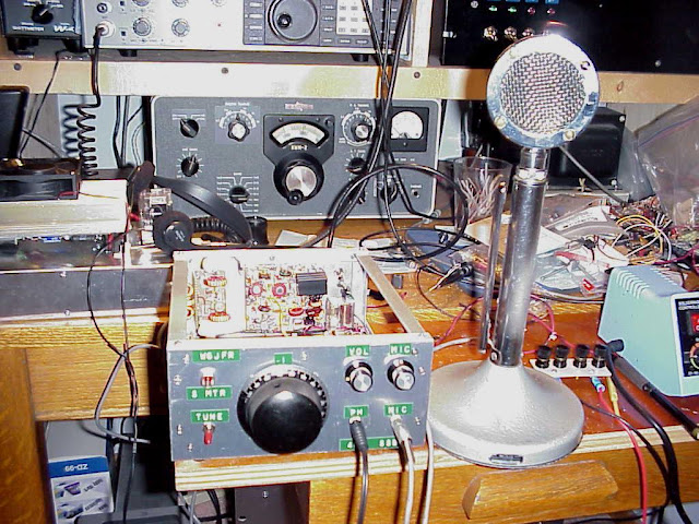
I learned a lot about packaging engineering when I built my 16 cubic inch shirt pocket SSB Transceiver. On the Critical Path for the 2X2 inch front panel was the size and how many I/O devices. This involved trade-off studies regarding how many controls do you really need and how many must be readily accessible.
This radio used a VXO (Variable Crystal Oscillator) and the toggle switch (on the panel below) controlled two crystals that gave it a 60 kHz coverage on 20M. I absolutely knew I was transmitting within 20M --but the exact place was a little macro versus micro.


A good example is the small board containing the Audio Amp and the Mic Amp. The final configuration had it located at the back of the transceiver and the Mic Gain a small 10K trimmer was accessible by a 3/16 inch in diameter hole in the back panel. But the volume control wiring was routed through the radio to a miniature 10K pot with a 1/8 in in diameter shaft to the front panel. It is all about packaging engineering. Note the shield between the LPF and the Mic Amp stage in the 2nd photo below.


That rig was built about 12 years ago and there have been huge technology leaps since that time. Likely, because we have seen the Glory of the magnificent displays, the Shirt Pocket Transceiver would have a 10X greater appeal as a project had it contained a real display like this 1inch square OLED

Or better yet this 1/2 size OLED. That is a Mechanical Pencil in front of the display.

Yet another project is the 5-Watt gem 6X4X2.

Yes, admittedly this is not as much fun as playing with your Nano VNA and characterizing 10 crystals for a brick wall filter. But if you want a finished product that is elegant and fits in your Lunch Sack then you need to noodle your way through the details.
Think in the Box for the unconventional. I found a plastic First Aid Case (less the Contents) for about $7 on Amazon and we now have our customized Bitx40 in that case-- all nice and portable. It even has the ability to key an outboard Linear Amp. I was thinking about one of those Chinese Amps that cost $20 and puts out 70 watts. Perfect for SOTA and POTA.
Lest I forget I figured out how to add USB to the Bitx40 by shifting the LO --yes portable FT-8 with this radio using an external digital adapter I designed + Raspberry Pi3. Yes, portable FT-8


Guys this is a real Chick Magnet --take this to a park bench (wear your N95) and set up for some fun -- better than a puppy!
The magic decoder ring is noodling first solder last! What we are doing is enabling a systems approach to the project -- this is not the time of haphazard soldering ugly style!
Updated 1/18/2022 (Crystal Frequencies.)
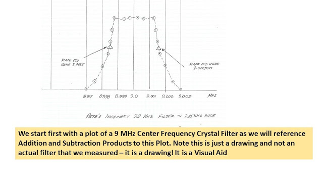
[Shazam Gomer Pyle! I just realized that Mouser sells two crystals that could make for some very interesting homebrew Crystal Filters. Here is what I tripped over. A stock 9 MHz (Cf) Crystal Filter has the BFO frequencies at 8.998500 MHz and 9.001500 MHz. I just spotted that Mouser is selling crystals in those two frequencies. So, a bit of Double Good News!
If you have a Crystal Filter but no BFO crystals -- you now have a source. But suppose you built two filters one with a Cf of 9.001500 and the other with a Cf of 8.998500 MHz, then you would only need ONE BFO crystal at 9 MHz. To switch sidebands, you simply switch filters. I happen to have two homebrew transceivers that use this method -- so did R L Drake!
OK Boomers time to noodle two filters.]
Below is a Page from the Flex Radio SDR-1000 SDR Transceiver Manual. First to be noted is the Band Pass Filter Network. It would be nice to simulate one in particular filter that essentially would pass the band from 10-24 MHz (30M - 15M). The second piece is the op-amp device (OPA2677U $6.50 @Mouser) that would produce 1 watt output. Lots of possibilities for inclusion in a homebrewed transceiver project.
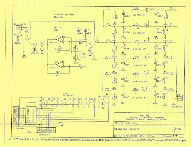

A quick and dirty plot of the 10-24 MHz Filter. This might be useful in future projects.

Now you should put this in LT Spice and do a little analysis work on your own. Changing R1 (only used for the Simulation) to different values seems to have little effect on the shape or BW of the plot. However, the R series in the generator does dramatically shape the plot insofar as flatness and bandwidth. Try it and then get a really warm feeling in your undershorts that MATCHING is important!
The OPA2677U is a SMD Op-Amp part containing two amplifier stages in one package. The Zin/out for each stage is 50 Ohms and good to 200 MHz. READ the datasheets! Nice!
Now some matching transformers are specified for the input and output to the amplifier block. For the Input side it is 4:1, and on the Output is 1.5 to 1. So, what are the transformers? A 4:1 can be 12 Turns and 6 Turns. (144/36 = 4) and the 1.5:1 can be 11 turns and 9 Turns (121/81 = 1.49382716:1) But the biasing resistors must be exact --No substituting and 1%. BTW you can check the 6 turns (12.6 uHy) to see what its impedance is at 24MHz and 10MHz -- 1900 Ohms and 792 Ohms --so OK in relation to 50 Ohms. [This is about circuit loading.]
Updated 1/15/2022
In our last Blog posting we talked a bit about the ubiquitous homebrew Crystal Filter; but now how to transition that filter into a radio. I can rightly say having built stuff since the early 1950's much has changed about the homebrewing mentality.
Firstly, who can accurately describe the Sideband Inversion phenomena? Concepts such as this are key when you scratch build a transceiver as often this drives the design and functionality. With the proper choice of a Filter IF frequency only one BFO frequency is required to deliver USB on 20 Meters and LSB on 75 Meters -- like a two-band freebie.
So, what is this Sideband Inversion stuff? Briefly as a result of a chosen mixing scheme (LO Above) what was transmitted as a USB signal after the mixing process actually becomes a LSB signal in the radio following the mixer. Joel Hallas, W1ZR in QST provides a simple guide. If a Modulated Signal is subtracted from a non-Modulated signal, then the Inversion occurs.
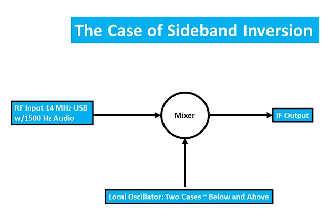
So, now we have this nice graphic but just how does it play with the LO Below and the LO Above. The first important thing to remember is that if signals are to PASS through a Crystal Filter those signals must be within the filter pass band. Any signal outside the pass band will be rejected.
The degree of rejection is dependent purely upon how "GOOD" of a filter it is. This has two aspects (maybe more), but certainly the filter bandwidth and the skirt selectivity, which are driven by the number of crystals in the filter and the capacitance values within the filter assembly. The output amplitude and constancy thereof are driven by the Band Pass Ripple which is a function of the matching transformers.
If you haven't guessed by now this is a highwire balancing act and goes far beyond slapping four crystals of the same marked frequency into a circuit, using five 100 PF caps for the filter caps and a 4:1 matching transformation. Once done you may not be able to declare victory as the perfect filter! If by luck it does happen --then buy lots of lottery tickets as you are indeed lucky. But our homebrew filters need a measured process and not luck to have them function properly.


The Case of No Inversion ~ LO from Below


BTW the 2 Band Freebie is a special case where the IF is at 5 MHz and the LO is at 9 MHz.
A 40M HB SSB Transceiver with a Home Brew Crystal Filter
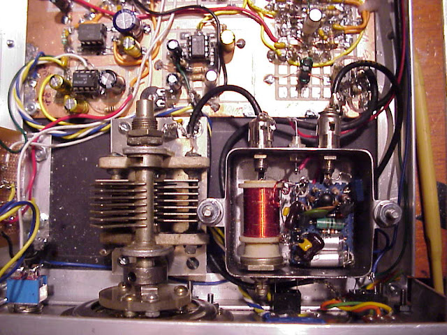
Yes, you are looking at the guts of an Analog VFO built by N6QW (then W6JFR)
A great deal of mechanical alignment was required to install the main tuning cap.
In the old days the homebrewer started by looking thru the Junk Box to see what was there or what could be adapted for use in the radio. In those days you never threw anything away and were constantly on the hunt to add to your parts stash.
Cases were not easy to come by, so you learned how to build a case. In those times mechanical assembly was just as important as the electronics in the box.
BTW I didn't have an S Meter, but I figured how to flash an LED based upon a pre-determined received signal level. So, if it flashed, I could say with confidence you are hitting S9. Look closely at the front panel and see if you can spot the S Meter.
Now the scenario today is like "the only way to homebrew is":
- Where can I get the Circuit Board? Or
- Email me the Gerber Files so I can have boards made.
- Who supplies the kit parts?
- Where is the BOM so I can send it to Mouser or Digi-Key?
- How come the code is not on a Git Hub?
- Why did you use NE602's, I heard they were bad?
- Would you build the radio and sell it to me?
- My friend built something like this, and he was unhappy.
- My radio doesn't work what is wrong with your design? Or
- I substituted some of my own circuits versus yours and the radio doesn't work. Why?
- My Radio only puts out 5 watts (IRF510) what is wrong? (Like I had Crystal Balls?)
I have been cautioned to be kind to new homebrewers as I seem to offend them. Well like my mother always said --if the shoe fits, wear it.
Back to the question of how to transition that filter into a rig. It all starts with a process and step one is noodling a block diagram. Step one is not to heat up the iron and just start soldering parts.

The block diagram also facilitates the board layout in the final build. Yes, that is a 4.9152 MHz Filter in that radio and the LO is from below (runs around 2 .2 MHz). This caused a lot of heartburn as I had to build some brick wall rejection filters to keep the LO out of the BPF.
This is where the LO from above (12 MHz VFO) would have been a better choice. But keeping a 12 MHz Analog VFO from drifting is like trying to entice Mary Jo (HS GF) into the back seat of the 56 VW Beetle. The LO from above would cause sideband inversion and so you would have to find a suitable BFO crystal to work in the radio --assuming the Crystal filter was somewhat symmetrical as that was another hurdle.

73's
Pete N6QW


