I received an email concerning my January 19th Post stating " why didn't you start out by saying buy a Tiny SA (Spectrum Analyzer) and a Signal Generator as first items versus a low cost General Coverage Receiver and building a Crystal Test Oscillator."
Somewhat pointedly I was also accused of eschewing new gadgets like the Nano VNA.
I strongly disagree with his suggestion for the 1st acquisition and secondly I have many new gadgets in the shack -- some I have designed and built myself.
My issue with the Tiny SA (Spectrum Analyzer) and signal generator is one of timing. Certainly these would round out the shack tool box just like a Digital Storage Oscilloscope. Keep in mind the rest of the original post was regarding a newly minted extra class licensee who had no gear, no experience and literally was starting at the bottom of the hill
But even a baby has to crawl before they can do a marathon. The email on the Jan 19th post was from a seasoned experienced engineer who perhaps forgot the initial premise -- the requestor was a newbie who asked me the question and shared that he was starting from below grade (underground).
My disdain of the Nano VNA directly links to the new users who have not read the manual nor bothered to watch the You Tube Videos or even calibrated their device. Do you think the scenario would be any different with a Tiny SA in the hands of someone who has no experience and literally got his extra ticket by filling out a box top?
Not too long ago I received an email from another individual who was just starting out and who took on building my P3ST design. Today he is in luck as he can buy a kit from K7TFC.
This individual built the 20M Band Pass Filter and immediately connected it up to his Nano VNA, took some photos and emailed me. The text said look at the photos, what is wrong with your design? The photos showed a peaked response. In less than one second I knew the problem: his section coupling capacitor in the BPF was too small. If it was too big you would have a double humped response.
My email back to him said you do not have the right size of cap which is supposed to be 1 PF. His email back to me: "Now where am I supposed to find a 1PF cap." Are you serious?
There are at least three answers to that question but all three relate to the laziness of those who want to be home brewers but do not want to educate themselves with some formal research. The 1st answer comes from W7ZOI in SSDRA (Solid State Design for the Radio Amateur) where in the appendix Wes shows how to scratch design a band pass filter. He also shows a method for creating small values of section coupling caps. (Ahhh 1pF)
The second answer is to look in Mouser and Digi-Key where they have 1206 size SMD 1PF NPO caps for pennies. That size can easily be soldered between two Manhattan pads.
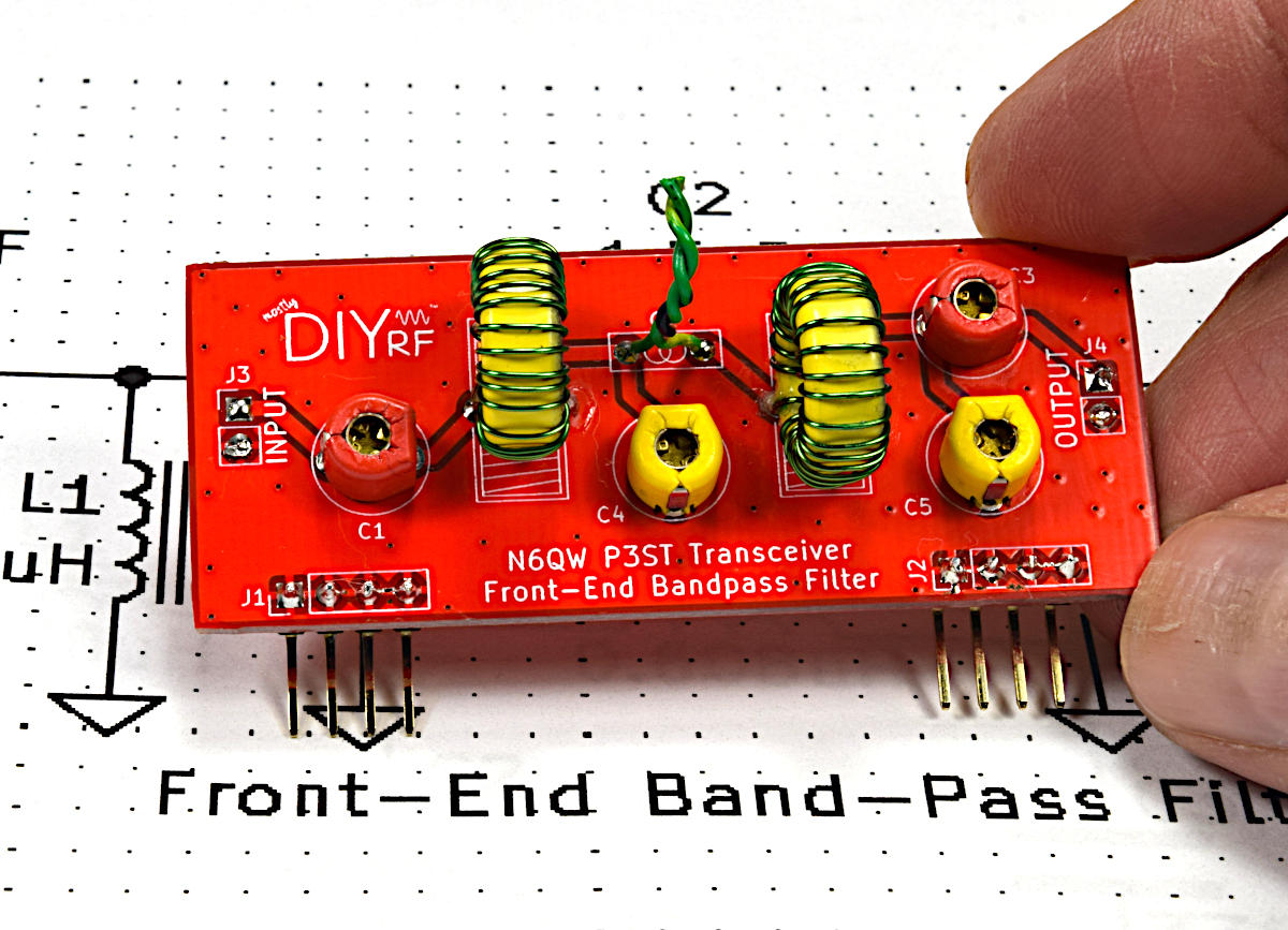
The third answer was to make a gimmick out of two pieces of twisted solid insulated #24 wire. About 1.5 inches is a good start and then it can be clipped to the right size to give the proper band pass.
Wait for it. The response back to me was I never built a gimmick and it won't work because the wires are too floppy. NO that is not true, but he does have a Nano VNA which he does not know how to use.
The below photo is from the https://mostlydiyrf.com website and the P3ST page.
Boom the BPF with a Gimmick.

To the seasoned engineer there were techniques for testing way before the advent of these cheapo miracle units. Simulation is a good start where later the results can be verified with alternate methods other than a $45 Tiny SA. Twice in the 19th posting I said, "Start Small and Start Wisely"! Getting a toy tool is not the smartest or wisest thing to do when you are starting from Zero!
I also suggested to the original requester that in addition to LT Spice he acquire SSDRA and publications by DeMaw as there are tons of solid projects including simple homebrew test gear that will provide the foundation to move on to the modern test gear. Strikingly those several publications have no mention of Nano VNA's or Tiny SA devices. Caveat Emptor: avoid buying EMRFD as a 1st book. Later, Maybe.
Can you see the problem. This ham thought by purchasing a Nano VNA that this made up for the deficit in his knowledge base. Actually the Nano VNA was giving him the answer -- he just did not know what he was seeing.
My follow on to that ham who stated my design was wrong and that was to download LT Spice (free) and he would see the result of the too small or too large section coupling capacitor. Later when he gets some time under his belt he can go back and learn how to use his Nano VNA. This is sort of like graduating to Big Boy pants.
The 20M BPF Design
1pF Coupling Cap
0.2pF Coupling Cap (Too Small)
3pF Coupling Cap (Too Big)
LT Spice can tell you the effect of the wrong size coupling capacitor and the Nano VNA told the newbie the answer but he immediately thought the design was wrong. The problem was the user and because most of those starting out simply do not have the foundation and background are inept at using these miracle devices right from the get go. This is something our seasoned engineer has failed to realize.
The two photos of my Homebrew SSB Transceivers are simply so there is a hook to get you to read the text otherwise: no pictures no reading.
73's
Pete N6QW

