The Final Filter! A Gasoline Company once used that slogan in its adverts. But today we are talking about a Low Pass Filter as the Final Filter!
Often an afterthought, typically the last item built and subject to the same maladies as the Band Pass Filter, the lowly Low Pass Filter is the last line of defense. You know sloppy wound toroids, poor tolerance (often wrong value) capacitors! But its job is too keep the harmonics, spurs and garbage artifacts from being a part of the Fire in the Wire.

The DE-5000 LC Meter ~ $140 @ Amazon.
In yesterday's post I mentioned the AADE LC Meter which 20 years ago cost $100. This above meter was suggested by a blog reader as a modern version to replace the AADE which is no longer available. Yes more than your $30 Nano VNA but far more useful in validating individual component values!
So let us get down to it and talk about Low Pass Filters. Mistakenly some think the only job of the Low Pass Filter is to provide a cutoff of "fire in the wire" just slightly above the operating band. You know you have a 40M SSB homebrew Transceiver and you want a cut off say starting at 7.5 MHz and 3dB down at say 8 MHz.
Now what is so special about 3dB down also known as (AKA) the half power point. Time for some math. You have a rig that puts out 5 watts (5000 milliwatts) with 250 milliwatts of drive to the final. Thusly, 10*(log(5000/250)) = 13dB (same example as several posts ago).
Now if you are only getting 2.5 watts (2500 milliwatts) with 250 milliwatts of drive then our math is 10*(log(2500/250)) or 10dB. the difference is 13dB-10dB = 3dB or half the power which is down by 3dB.
It is not that your actual power in the amp went down by 3dB it is that any signal beyond the Low Pass Filter Cutoff Frequency is down by 3dB which is just slightly (Hopefully) past the Fc.
But we are not done with the LPF attributes for not only should we consider the Fc but importantly the attenuation of the 2nd Harmonic. You want any second harmonic signals from the 40M homebrew rig to be notched out. Thus any 14.0 to 14.6 MHz energy is notched out and not in the wire. Repeat: 2 jobs!
Here is a 40M LPF popular from the 1960's and you might even see it in a circuit from one of the big guns who had a prolific amount of published articles.

40M LPF

3dB down is at 7.7 MHz.
So with that filter installed we move right along thinking we nailed that puppy! The Fc is good and 3dB down is just outside out of the operating range. Even your $30 Nano VNA will affirm the plot assuming the inductors are the right value and the caps did not come from Banggood (love that name). Note the curve only shows an attenuation of the primary operating frequency.
Enter the seminal publication by W3NQN which is based on the simulation program called "Elsie". Here is the form of a W3NQN 40Meter Low Pass Filter.


The Fc is 8.5MHz but the 2nd Harmonic is -100dB down
Intuitively obvious (even to your $30 tool) is that the W3NQN LPF is better at addressing the 2nd harmonic than that the filter from the 1960's.
Bill, N2CQR has several times related in his early days on the air (@ 14 years old) that he got a call from a ham saying: Hey Kid get off the air, you are transmitting on 20M!
In the old days you might receive a post card from an OO (Official Observer) that you were transmitting out of band. I believe the OO has gone away just like you no longer see substance in QST.
In the past, the out of band problem arising from Harmonic energy was likely traced to the form of the coupling to the antenna. In a presentation I did to the G-QRP Club Virtual Convention during Covid19, I highlighted a design presented in QST for a simple CW transmitter that was noted as being rich in harmonics and used only link coupling to an end fed long wire antenna. So where do you think those harmonics are going?
As a part of my pitch I showed a one tube transmitter I designed/built that had a W3NQN on the output side. (Right side of Photo)

BTW some ham is selling a transmitter looking just like this one on eBay for $200 a pop. The sad part --it is not me collecting $200 for something that can be built for $50.

Some critical points from my LPF presentation today. Firstly, use the W3NQN filter design and noteworthy his paper which can be found on the internet and also available at the G-QRP website has designs for all of the bands and importantly has been optimized for standard value capacitors. Use of 500 Volt Silver Mica Caps is a really good idea.
So the burning question how in the hell does he get the notch at the 2nd Harmonic? Look at the middle inductor and its resonating capacitor. Put this design in LT Spice and diddle with those two values and watch the plot change.
I have even found that the Communications Concepts Inc. Low Pass Filter Board Kits (about $15) can be easily modified to become W3NQN filters.
Final comment. Any LPF is only as good as the care with which it is built. Sloppy toroid winding will show up on your Nano VNA not as a bad design but your poor construction!
Over the past several weeks I have attempted to present "modules" of a SSB transceiver and highlight some of he "black art" that will make them work. My hope is that one or two blog readers will take up the iron and build something.
This is not a new problem in the ham world and here is a preface to a project from the late 1950's that took war surplus conversion to a new height where a BC-453 radio receiver operating from 100 to 500 kHz with an all important 85kHz IF was converted into a SSB Transceiver. The design is from Ed Marriner and Ernie Mason. (W6BLZ and W6IQY both SK's) Even in the late 50's and early 60's homebrew was on the decline!

For you Latin Enthusiasts the reference to Cave Canem translates into "Beware of the Dog"!
A bit of history for you. While in High School I had to take two years of Latin. The 2nd year involved a project. So always ahead of the curve, I noted that my Dad was into creating mosaic artwork. Yes I convinced him to make a similar piece for me with me doing some of the gluing of the tiles. It was about paper size. That was my project. The original piece was in Pompeii which I saw while I was in the Navy.
When I brought it into school and presented it to the teacher, Ms. Virginia Bushnell, a spinster with a love for Latin -- she started to cry -- I knew it was an instant A -- and so it was.
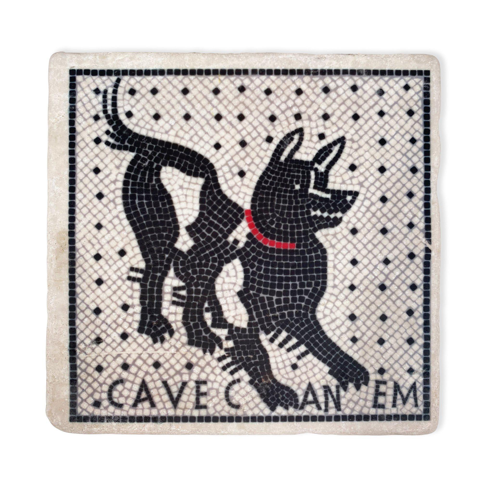
The Original Not What I Did!
73's
Pete N6QW