Some Tips and Tricks for the Homebrewer!
What I am about to share with you, I consider superior to the glue down Manhattan type construction. The benefit is that no glue is involved, you have a continuous ground plane and you can make circuits very compact!
The method of which I speak is the use of Single Sided Copper Vector Board*. Below is what the board looks like. If a component is grounded then it is simply passed through a convenient hole and soldered to the top surface. Don't forget to clip the excess lead length on the other side.
For those components which are not grounded and connected to other components on the insulated other side, these are passed through hole which is reamed around the top surface with a 1/8 inch drill bit so no shorting. I use aluminum pillars, one in each corner and then the assembly can be installed on an aluminum bottom plate, inside a chassis or even on a piece of copper board. It is all about grounding.
I am providing the link to save me from having to answer emails on where do I buy this? Previously I simply answered the question from a prior post and said Digi-Key to which I got the usual I can't find it --yep a BTE.

But actually our process starts with a chunk of plain old perforated board and the schematic. Step one is to take the actual components and trial fit them around the device. Nearly all of the time I use sockets. But you will see above that the IC (LM380N) is set on the board and the ground pins will be soldered to the top board. These are also heat sink pins.
Usually this process takes several trials so that short direct connections can be made and no (minimum) cross overs. It takes a bit of practice but this can be done quickly.
The next step is to take a digital color photograph of the trial circuit so that when you use the copper vector board you have a photo of where and what goes where.


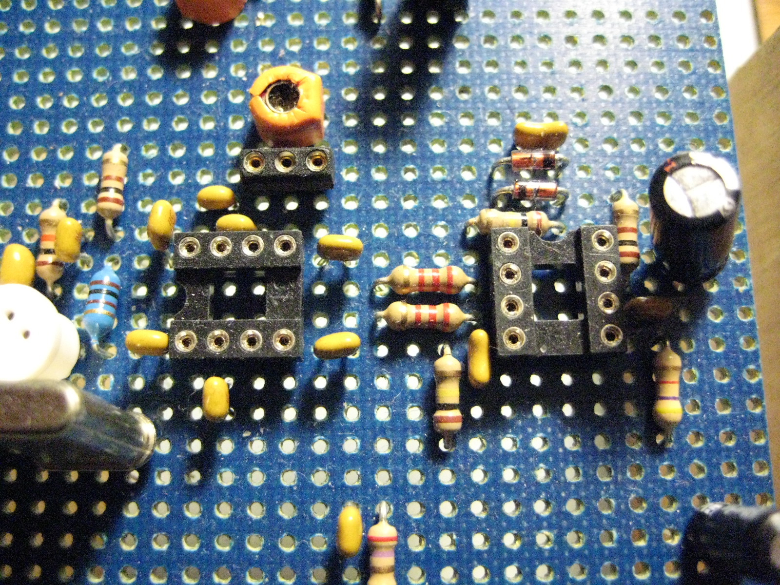
Above are some photos of the trial layouts and the additional benefit is that you want a second board -- you have the road map.

The above is the W7ZOI HYCAS Board with an S Meter and Product Detector and there is only one cross over wire! See if you can spot it? If you did this Manhattan style you might still be working on gluing down pads.

Underside of the HYCAS Board
The other Big Bonus is that the Vector Board provides a foundation for a shielded enclosure as shown below.

Post Mixer Amp, HB Filter and Transmit Amp. Relay Switched
The net result of my approach is a solid circuit, short lead lengths, capabilities for shielding, ease of construction and it doesn't look like a jumbled mess subject to shorts!
A power supply tip for you and that is the use of the LM317LZ regulator. This is an adjustable regulator and super convenient when you want something other than 12 or 5VDC. The Seeed Xiao RP2040 uses 3.3VDC and this would be a good device for a starting place. For a 3.3VDC output then keep the 220 Ohm and the variable resistor is set to 361 Ohms.

So a few more tips to use when you homebrew.
73's
Pete N6QW


