Check the Soldersmoke Podcast #250 on You Tube, where at the front end, Dean, KK4DAS and Bill, N2CQR talked a bit about their High School Direct Conversion Receiver Project. Bill mentioned that several hams are building that project and were encouraged to build a mating Transmitter and to get on the air.
This guy is standing in the room and we all missed him! If our hobby is to survive then we need to keep up our technical skills. The very foundation of our hobby was built on stretching the envelope by learning and doing. Flashing the plastic is not a technical skill -- it is surrendering to the buy it now genre.
My February 7, 2024 blog posting shared the Direct Conversion Receiver article I wrote for QRP Quarterly in 2011/2012. There was a Part Two to that article and that covered the companion Transmitter which is being presented now.
As I explained in the article, the transmitter is on four boards as that is what I had as stock. On the left side is a free running Crystal Oscillator that has a small tuning range (VXO) and when you hit the Key is powered ON and held ON for a time period you can adjust.
The Board on the bottom running left right contains the NE555 circuit that is keyed and provides power to the Oscillator and also powers the TR Relay and provides a voltage to mute the Receiver.
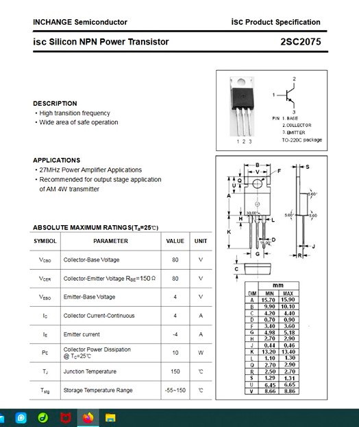
To the right of the NE555 is a 2N3904, a 2N3866 and a 2SC2075 (aluminum plate heat sink). The top center board is the TR relay and to the right of that is the W3NQN Low Pass Filter.
The Top Plate and Front Panel are PC Board. The sides and back apron are hobby type wood. A significant amount or wiring is done under the top plate PC Board. By design the wood portion is 2 inches high as you could fit a battery pack in that space for portable operation. See, I think of all possibilities when I build something.
A bit about the circuit. The NE555 came from W7ZOI in SSDRA and part of the transmitter circuit 2N3904/2N3866 is straight out of EMRFD. (Yes, I finally did find something useful in that publication.)
But, the 2SC2075 Final RF Amp was my add and this is good for about 4 watts. The Michigan Mighty Mite and the 10 Minute Transmitter will put out RF and you can be spotted on the Reverse Beacon Network. If the planets align you might get 150 milliwatts out of those two rigs. But at 4 watts that is 4000 milliwatts and so that is 14.3 dB of gain that you would have with my suggested rig. [4000/150 = 26.7. Thus 10*log(26.7) = 14.26 dB. ]
Supposedly the EMRFD circuit can put out 500 milliwatts. I never saw that level of output with any project where it was used. But if you could get that level then you would only need a RF gain of 9dB in the Final for 4 watts out. 4000/500 = 8 and thus 10*log(8) = 9dB.
An important note here especially with Final RF Power Amplifier stages, while the stage may be capable of significant power output it may not actually do that as the issue is insufficient drive to the stage. I chose the EMRFD circuit because of its touted output level (500 milliwatts). The 2SC2075 most likely would peak out at 12 to 13 dB. Translated that means you need to have 250 milliwatts of drive for 12dB, or 4000/250 = 16 and that is 10*log(16) = 12dB. In passing the most often output I ever saw from the 2N3904/2N3866 was 250-300 milliwatts.
RF Parts has the 2SC2075 for about $8 each. Before you hit the "buy it now" button that device was designed for the CB Radio market and good for 4 Watts AM. You might find it less than spectacular for linear operation. BUT this is a CW not SSB rig!
Now we did not show an Oscillator as the article mentions you have lots of choices and any oscillator would do. Our test oscillator presented earlier this year would work here as it is not keyed. But I also suggest you could build a VFO but turning that on with the NE555 is asking for drift.
This is a perfect place for a Si5351 and Arduino where the "enable CLK2" code would turn on the required LO and you could even build in an automatic offset of 700Hz.
Here is the Test Oscillator mentioned earlier. However for this Transmitter swap the 7030 kHz with the 5185 kHz crystal and the source voltage comes from the NE555. Of Note there is a 4.7uF cap on Pin 6 of the NE555 and that sets the "hold" timing. Making that smaller makes the duration shorter. Making it larger rivals growing a beard. I find that 4.7UF is about right for 15wpm.
For those who think I perhaps should have just connected the input to the Varactor Tuned Oscillator in the Receiver, that is a bit of a problem. Because you would always be Zero Beat, you would have to build some sort of offset into the scheme. That would make things more complex. I think I included a spot switch which just powered the oscillator on during receive so you know where to tune the small variable. The switch on the test oscillator could be configured to select two 40M crystal frequencies thus expanding the frequency agility range.
This
turned out to be a pretty nice rig. It was another concierge
project where I was asked to design a mating transmitter for the DCR. I made
the usual one contact and moved on down to the SSB highway.
73's
Pete N6QW


.webp)

