The Simpleceiver Plus Superhetrodyne!
10/10/2017 ~ ADE-1 Product Detector Fitted to the Simpleceiver Plus
I have temporarily installed (polite words for hay wired) the ADE-1 Double Balanced Mixer in place of the original J310's used as a Dual Gate MOSFET Product Detector. This was done to facilitate the transition to the SSB Transceiver. You can listen for yourself in the two you tube videos below. I am satisfied with the result and this greatly simplifies the build -- a lot less parts and ease of transition from receive to transmit. The ADE-1 has but four connections with Pin 6 being the BFO input and Pin 3 is the RF input and Pin 2 is the IF output (AF in this case). Pins 1, 4 and 5 are grounded
I have had some further communication from Johannes in downtown Freiburg, Germany. He has completed his Simpleceiver Plus SSB transceiver and sent along some photos. I am including several of the photos. First I want to complement him on his building of the filter. The curves show what can be achieved -- and he for the most part used the method I described to build the filter. So if he can do it so can you -- this was the first ever homebrew filter for him! Johannes first started with the suggested cap values and then with a bit of judicious experimentation achieved the shape factor below. Of significance is that it has a good ripple factor (maybe less than 1 dB) and it is symmetrical which says that it should work well on either sideband.
 |
| Johannes Final Filter
Below are two photos of Johannes finished Simpleceiver Plus SSB Receiver. I suggested to him that he build a second version only this time instead of a single board to construct the radio in modules and install them on a bread board. The reason for this is that this then becomes an experimenter's platform where you can test filters, RF stages, product detectors, audio amplifiers, LO's and Display's. I have one of these and it makes for any easy task to check out new circuits in a complete radio.
I should mention that Johannes is using an AD9850 for the LO and a local crystal oscillator for the BFO. His next step is the Si5351 for both the LO and BFO
 
|
I must apologize for some delays in getting circuits published and moving along with the project. But I think the way forward has a clear path.
73's
Pete N6QW
10/05/2017 ~ Data on the Crystal Filter Build
Johannes in Freiburg, Germany has successfully built a 12 MHz Crystal Filter using the process suggested in this blog. From the git go it was an iterative process and not simply a matter of reaching into a plastic bag and pulling out four crystals and you are there. His "final filter" is data based using analysis and drawing inferences of what needed to be changed and doing so in a very measured fashion. If a prospective builder is not up to investing the time to do this, then you best purchase a commercial filter!
In May of this year the Chief Radio God himself, Wes Hayward W7ZOI published a document regarding our beloved computer crystals and how the physical sizes of the quartz devices are much smaller today (reducing costs, automated production methods notwithstanding) which in turn affects their use in crystal filters.
My Synopsis of his paper = Harder to Do--but still doable! There is another factor and that is something shared with me by the one or two homebrewer's who were actually successful in building a crystal filter using the Dishal method. Both shared that it was the brand (manufacturer) of the crystal that made a difference.
One individual shared his research indicated only CTS Knights Crystals worked and could reliably follow the parameters spit out by the program. I am not sure what brand of crystals Johannes used but the brand I use is ECS. So some of the differences in capacitor values from where I suggested you start very likely relate to the different manufacturers. The values I specified will put you in the ball park; but you very likely will need to adjust the cap values to put you in the correct section and row.
What you will see next is data from Johannes that starts with the values from the blog. Then through a process of measured changes and further data analysis, Johannes reported he found "the sweet spot". His data mining found that his 68 PF clearly marked caps were 68 and 73 PF after measuring them. It is important the values used be really close in value (where there are multiple caps) and close to values specified. 135 PF is not 120 PF!
Secondly as you go through the process of refining the cap values --change one thing at a time or you will never be able to track what causes a significant change and or improvement.
 |
| Sorry can't figure out how to rotate this --note the 68 & 73 PF caps |
 |
| Here Johannes changed the Matching to 200 Ohms and tries three different values for the end capacitors -- still too wide but ripple appears better. |
 |
| One of the early runs -- Several Subsequent Runs Addressed the Band Pass Ripple This filter is a bit wide --but a starting place!
|
 |
| Here Johannes changed the caps and you should be able to see that in large measure the filter bandwidth is driven by the three capacitors to ground. Compare to the chart above.
|
 |
This is the "final filter" and the much narrower bandwidth
Finally we have a photo above of Johannes "test setup" that he is using. I would suggest that perhaps he should take one more step as I think the filter is sufficiently narrow for use in the Simpleceiver Plus. He now may want to go back and adjust the matching transformers as his last run was with a Z in/out of 200 Ohms. Don't touch the caps but try a run at 100 Ohms (7 turns to 10 turns --- 49 and 100. 100/49 = 2:1)
I would bet after that impedance change the top of the curve would look a bit like the fashion model "Twiggy" -- kind of flat on top.
|

73's
Pete N6QW
News Flash ~ A heads up from Charlie ZL2CTM.
A supplier has integrated an OLED display right on to an Arduino Compatible Microcontroller board and I think the price is about $10 USD. This open up some possibilities for shrinking our rigs down really small. Check this out below. Don't know how well it works or if there are RF noise problems but this is a huge step. The processor operates at 240 MHz and as you know the standard Arduino operates at 16 MHz. It also includes a Wi-Fi chip and USB interface. That is all I know.
73's
Pete N6QW
10/4/2017 ~ Some follow on regarding building Crystal Filters
One of our builders has shared information with me regarding his efforts to build the crystal filter using the method I previously described. Later I will be posting some data that he shared with me; but wanted first to discuss some observations and cautions regarding the actual building of the filter.
The data shared with me showed a filter that had a bit of ripple and was too wide for good SSB usage. But the filter shape overall put in the ball park and a really good start. As I suggested in the earlier posting changing the matching transformer ratio will smooth out the ripple. So it was that his ripple did improve by making that change. But that still left a filter that was too wide -- shades of Dishal.
The filter bandwidth is markedly affected by the values of the 5 capacitors --less capacitance = wider bandwidth. The two outer capacitors were specified as 68 PF and the three caps to ground were 120 PF on either end and a single 150 PF at the middle.
- First and foremost you must use capacitors that are close in value by 1 to 2%. Our builder used two capacitors marked 68 PF on the outer interconnects; but on actual measurement one was 68 PF and the other 78PF. It is important that both caps be either 68 or 78 PF --not one of each. Thus you might have to do some capacitor sorting to arrive at values that are very close to each other. The same holds for the 120 PF caps and the 150 PF.
- A critical point once you have an initial plot is to not change too many things all at once! My advice to the builder was to first address the ripple factor, which he did and his plot results indicated that there was an improvement in the ripple (flatness at the top of the curve). So that is a key piece of information. You could see the change by changing only one element!
- The builder next changed the two outer capacitors (getting them closer in value and I think moving them to 100 PF). There was some change in filter bandwidth but it was still too wide. So another piece of data for you in that we can see that the bandwidth is very likely more affected by the caps to ground (120 PF and 150 PF). He will be running those tests.
- Our builder also thought his generator (an AD9850) might be presenting something other than 50 Ohms input. Resist changing anything on the generator until you can see the bandwidth shrink. Keep in mind it would be the ripple that would be more affected by an impedance mismatch more so than the bandwidth.
- This iterative process is not done! Once the bandwidth has been shrunk then you may need touch up the ripple factor. But our builder's experience is invaluable in identifying that change only one thing at a time so you can readily see the effects of the change.
- What I haven't discussed is that after the change you might find that the center frequency of the filter will shift. I saw that in the plots our builder sent me. Knowing the Center Frequency will be required in order to set the frequency of the BFO for USB/LSB selection. As a starting point once you find the Cf --then pick frequencies 1.5 KHz above and below that for the BFO input.
- The process in #6 is a starting point for finding the BFO frequencies. What I usually do is to connect a separate RF generator to the BFO port and then listen by ear what sounds the best. You would be amazed at how accurate that computer between our ears can discern small differences. If it sound natural you are probably very close.
Later I will post some of his plot data so you can see the initial filter and the final results.
73's
Pete N6QW
9/27/2017 ~ Early Simpleceiver Plus SSB Transceiver Concepts
Any designer worth his salt will look to ways of simplifying any circuit without compromising performance. Thus some thoughts about the design simplification as we move to the SSB Transceiver configuration.
The first simplification (change) has been previously discussed and that was to change the active device product detector comprised of two J310s to that of a packaged Double Balanced Mixer such as the SBL-1, TUF-1 or ADE-1. I will be using the ADE-1 as I have a stock of those. All of those devices are 7 dBM which means they need a max of 1.4 Volts Peak To Peak of RF Drive which is easily done with the Si5351. I will be providing a hookup schematic --so untie that knot in your underwear.
Further simplification was pursued in the form of keeping the basic IF Amplifier Block Module (the 1st IF Amp, Crystal Filter and 2nd IF Amp) as a unit and electronically switching the signal direction through the Block Module so that it would operate both on receive and transmit.
This also simplifies the circuit ahead and following that block module. Ahead we have the SBL-1 [or other DBM] which now is both the Receive and Transmit Mixer stage with the LO always connected to the device. Following the IF Block is the 2nd DBM which on Receive is the Product Detector and on Transmit is the Balanced Modulator. The LO Port on this DBM is always connected to the BFO. Additionally the IF Port connects to both the input of the Audio Amplifier and the output side of the Microphone Amplifier. Again keep your cool as those schematics will also be provided.
Now I want to focus on how to electronically switch the IF Amp Module so that the signals pass through the amp stage on both transmit and receive and this is shown below with my initial noodling. You are encouraged to trace the signal paths based on how the diodes are biased. Note: check Charlie Morris, ZL2CTM current crop of You Tube videos and he is doing the same thing with a SSB transceiver he is now building that uses both a SSB Filter AND an SDR Back End.
You'll need about four each of 22K 1/4 Watt resistors, two 1K 1/4 Watt resistors, four diodes (any of those shown) and six 10 NF caps plus one additional Double Balanced Mixers. All input and outputs are at 50 Ohms. The output of the 2nd IF amp might have to be adjusted to 50 Ohms (as I don't recall what is in there now) .
Keep the leads short and I must apologize to those who have designed boards for the Superhetrodyne that this approach might have been nice to have been known earlier.
The notes try describe how the forward / reverse biasing of the diodes causes the signals to be steered in a single direction through the block yet take advantage of the bilateral nature of the Double Balanced Mixers.
The RF Amplifier Design could be simply replicated for the low level transmit pre-amp stage. Again diodes could steer the signals from/to the BPF to either the receiver RF amplifier or Tx Pre-Amp stages. The Band Pass Filter which is always connected to the SBL-1. Diode Steering could be also employed to switch in various banks of Band Pass Filters if you chose to operate on several bands. Charlie, ZL2CTM has a video on how he is using the diodes for this purpose.

Once we get past the Tx Pre-driver stage next will be the low level transmit RF Amp which will use a 2N2222A and a BD139. The Final Stage will be the venerable IRF510 which will make the SSB transceiver good for about 5 watts output.
As I hope you can see -- once you get the Superhetrodyne receiver built the move to the SSB transceiver is not that much more difficult.
Stay tuned more schematics to come -- so unknot your underwear. [These will include the Tx Pre-Driver (you could take the J310 Product Detector and reconfigure it for this --nothing wasted), the Driver Stage (2N2222A/BD139), The IRF510 and the Microphone Amplifier ]
Stay tuned more schematics to come -- so unknot your underwear. [These will include the Tx Pre-Driver (you could take the J310 Product Detector and reconfigure it for this --nothing wasted), the Driver Stage (2N2222A/BD139), The IRF510 and the Microphone Amplifier ]
73's
Pete N6QW
9/26/2017 ~ Building the Crystal Filter and Other Modifications
In preparation for the Transceiver build there are a couple of changes that need to be made. The first change is that the Product Detector using the dual J310's will now be converted to a Double Balanced Mixer such as the SBL-1, TUF-1 or ADE-1. This is done so that when we go to the transceiver configuration the Product Detector will become the Balanced Modulator.
You can even homebrew a DBM and there are three You Tube Videos by N6QW (and others) on how to do this. I don't recommend the homebrew variety. It is very difficult to achieve the performance that you get with a commercial unit. Many homebrewer's despite the three videos got their wires crossed and the end result was a disaster.
I have limited time today so I want to list three things you will need to build the filter. The first is at least a stock of 25 crystals all on the same frequency. I used 12.096 MHz but 12.0 MHz will work nicely too. I paid about 30 cents a piece and these were not eBay specials (Mouser). Next you will need to build the G3UUR oscillator and the Internet abounds with info on how to do this. Third you will need a means of accurately measuring the crystal frequencies in a loaded and unloaded state. There are frequency counter modules that can be found for about $15 on Amazon and will give a readout to 1 Hz.
The method I will describe does not use any of the fancy software programs --you are welcome to do that, but what I will describe gets you close. AADE, Dishal and EMRFD all have programs you can use. But I had disastrous results with the Dishal program so maybe you will have better luck.
Do a search on this blog for Simpleceiver 16 for my initial discussion about building the crystal filter and those values worked! Below is the schematics of two filters as described in Simpleceiver 16. I found it interesting that the values for the four crystal filter are similar to what you see for the four pole filter spit out by Dishal.
By way of review I started with my batch of 25 crystals and labeled each one (1-25) using a tape label machine I have. Next I opened a excel spreadsheet and with the numbers 1-25 made two measurements with the G3UUR oscillator. The first was to measure each crystal (using my SDR receiver) oscillating frequency in the unloaded condition. After powering up the oscillator I let it set for one minute to stabilize. Then I took reading in the unloaded state. Each reading was entered into the spreadsheet. I repeated that process only this time in the loaded state and took another set of readings. figure about 1 hour to do this.
Since there are so few crystals involved by visual inspection I noted the crystal numbers where there was no more than 50 Hz variation in frequency in the unloaded state. Next taking that grouping I looked for four that were close (within 50 Hz) in the loaded state. From these I picked the closest four and I now had the beginnings of a filter.
From my experience I have found that the four pole filters typically have a Z in/out in the 100 to 200 Ohms range. Starting with the assumption of around 170 Ohms I built a 50 to 170 Ohm matching transformer which turns out to be a 7 Turn to 13 Turn transformer on a FT-37-43 ferrite core. [ 7^2 = 49 and 13^2 = 169 --close enough for our work].
Connecting the crystals as I have shown them I inserted a 50 resistor in series with a signal generator source to the input matching transformer. On the output transformer I connected another 50 Ohm resistor and put my scope here. Then using the generator I started a 5 kHz below the nominal center frequency (12.096 or 12.0 MHz) and then with a reading every 100 Hz made measurements to 5 kHz above. I plotted the scope output reading. You can set the scope to Peak To Peak or RMS. When I had all of these reading (which were entered into a 2nd spreadsheet), I then had excel convert the values to dBm. (PTP^2)/400 and then multiplied by 1000 gives you milliwatts. Take 10 Log(milliwatts ) and you have dBm. Plot the dBm values against the frequency and you will have the response curve. It may not be absolutely pristine but it will be "Pete's Good Enough".
If you adjust the matching transformer to say 100 ohms which is a 2:1 the Turns Ratio will be 7 Turns to 10 Turns. You might find that there is an improvement in the pass band ripple as the Z in/out mostly affects the pass band. Next you can try 200 Ohms with a 7 turn to 14 turn (7^2 = 49 and 14^2 = 196) which gives you a 4 to 1 transform. Pick the value that gives the best curve.

Further experimentation could be done with the 68 PF caps at each end as these caps impact filter bandwidth. Larger values will narrow the bandwidth. Give that a test drive.
Now on my website I have posted DuWayne's [KV4QB] Sketch for his Arduino/Si5351 Board and that can be found at http://www.n6qw.com look for the link that says KV4QB sketch. It is in notepad format.
Should mention that Johannes has added more parts to his Simpleceiver Plus board and he is getting close to firing up his Simpleceiver Plus Superhetrodyne. In his build of the crystal filter he built used the G3UUR oscillator and went through a process similar to what we described to characterize his crystals. The Photo of his board shows the board populated less the four crystals, matching transformers and the capacitors. He is getting close. Nice work.

73's
Pete N6QW
9/24/2017 ~ An Email Report from PA3GUP
In my posting of 9/20/2017 I had shared that Jelle, PA3GUP had built the Simpleceiver Plus DCR and was working on the Superhetrodyne. Well he has finished the Superhet and sent me an email along with a photo of hos build. I am sharing his email (with his permission) so builders can hear about the performance from someone other than myself.
 |
| PA3GUP's Simpleceiver Plus Superhetrodyne
Here is the text of Jelle's email:
|
Hi Pete,
Success on the 9Mhz IF and filter build!
I put it all together yesterday, trinket with the LO / BFO offset and
ended up with a BFO of 8998500Hz (LO = RF + BFO).
Although a keen eye spots 12Mhz IF Amp written on 2 boards in the photo
its really tuned for 9Mhz.
Plenty of gain and loud audio, I use the 2N3904 + LM386N AF amp.
The pots on the IF amps are about have way.
Why did I join in? A while back I stumbled up on the soldersmoke
podcast, so I googled you work and found the simpleciever on youtube.
What struck me was how quiet it was between stations. I found the JH8SST
version also with the AGC. And then when you announced a series on the
Simpleceiver from DCR, Super to TRX I got really exited. Also I had
almost all the components needed in my bins.
Observations:
The DCR has a very good performance with few components.
The DCR is quieter then the superhet, noise wise. Of course I would say.
In the superhet I use a MCL TFM-2 mixer (saved from an old cable TV Amp).
The noise from the LM386N I reduced by adding a 1K resistor between pin
1 and the cap, effectively reducing the gain.
On the product detector I have followed your original design but I did
not have the 100mH inductor and put in 100NF caps and a 10mH.
For first time builders, go to hamfests, get your self some copper clad
board, FT37-43, T37-2, T50-2, T68-2, T37-6, T50-6, T68-6 and BN43 pig
nose cores. And look on internet for deals.
I got all my SMB connectors and cables in the pictures from hamfests and
old cable TV Amp boards.
Yes costs! For this Simpleceiver project I was lucky and only bought a
handful of 12Mhz xtals. But others I know are still gathering parts.
I find the 'muppet' Manhattan style very easy for building RF circuits
because it follows the schematic closely. And it is QUICK! I keep a
stack of 1"x1/4" single sided copper clad board strips so I can cut it
when I need an isolated solder point. I stick it on with superglue.
On equipment: I have a simple CRT scope, 2 multimeter's, a frequency
counter and a RC meter both simple home build PIC devices. That could
now easily be done with an arduino HI.
Now! Back on the original path and constructing the 12Mhz xtal filter. I
also will explore the uBitx version with the 8 xtals.
Thanks Pete for this opportunity!
Question: The output level of the SI5351. Any level tuning needed? [I set it for 8 Ma]
Best 73
Jelle PA3GUP
Thank you Jelle, for sharing your project. I also heard from him today and he shared the following: Initially his Superhet build was with the 9 MHz Commercial Filters. He has now built the 12 MHz Crystal Filter so we will be anxious to hear how that is going.
I must apologize as some personal circumstances here on this end has caused me to have a bit of delay in publishing the Crystal Filter info. That is at the very top of the list which should arrive shortly on the blog and I should also mention that I will be changing out the product detector that uses the dual J310's to a double balanced mixer like the TUFD-1 or SBL-1. So builders should add a DBM to the list of things needed. This change is to simply the build of the transceiver variant where the DBM will serve both as the Product Detector as well as Balanced Modulator.
73's
Pete N6QW
9/20/2017 ~ Builder Feedback on the Simpleceiver Plus DCR
I really enjoy hearing from project builders and getting feedback on what they have experienced or variations they have tried. It is all about what is in the junk box or trying new things. Jelle, PA3GUP has shared his Simpleceiver Plus DCR build and you can see his work in the photo below.
 |
| PA3GUP's Simpleceiver Plus DCR |
If you look carefully at the build you can spot the circuit module blocks and a really good practice is to solder a shield between the sections of the Band Pass Filter. I saw an evaluation of BPF's with and without the shield and the impact was not so much at the operating frequency but at much higher frequencies. So if you want a "Tight" BPF -- install the shield. I have installed the shield in some radios -- but I was just lazy when I made the BPF for this project.
Noteworthy is that Jelle is already constructing the Superhet and has chosen to use a commercial 9.0 MHz crystal filter in place of a homebrew 12 MHz filter. The IF amplifier circuit shown in the post of 9/16/2017 was modified by changing C1 to 68PF and C2 to 360 PF with all other values kept the same. Jelle reports that his LT Spice Simulation shows a max gain of 27 dB and a min gain of 14 dB. I had done a earlier simulation at 9 MHz using similar values with essentially the same results. We are looking forward to hearing more from PA3GUP once he completes the Superhetrodyne.
DuWayne has sent me code for use with his board (which I should note is a bit different, and better, then my code) I will post that on my website and will advise when that happens. His code will enable adding some features such as a signal generator mode and battery voltage measurement should you embed the board in portable equipment -- like I said better!
73's
Pete N6QW
9/19/2017 ~ Feedback on the Simpleceiver Plus DCR
First let me once again mention the Arduino/Si5351 Circuit board available from KV4QB that can be found here: http://kv4qb.blogspot.com/ I can attest that these are 1st rate boards and WILL shorten the critical path. Thanks again DuWayne for designing the boards and making them available.
Several days ago I posted information from Johannes in Freiburg Germany where he designed boards for the Simpleceiver Plus project. Yesterday I am happy to report that Joh has populated the boards and now has a working Simpleceiver Plus Direct Conversion Receiver. Congratulations Johannes as you now have experienced JOR -- The Joy Of Reception.
In typical ham fashion Johannes reported he first started inhaling RF at midnight, on his kitchen table using a 12 foot chunk of wire for antenna. It doesn't get any better than that! He sent some photos of his build which I will now post so other can see his work.
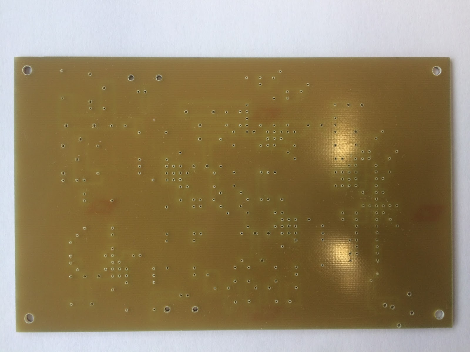
Starting with the naked board ...

Starting with the naked board ...
This is what resulted ...


We have since heard from Johannes beyond what he sent in these photos and he is continuing to work on the project beyond just the DCR and will soon start by populating the board with the Superhetrodyne components. So far he is a pretty happy camper. Thank Johannes for sharing with us.
I am aware of several builds in progress with the Simpleceiver Plus DCR. I would be happy to post photos of projects now in work. Send me your photos to n6qwham@gmail.com
My next posting will be "how to build the crystal filter". Also don't overlook the possibility of using a commercial filter for this project.
73's
Pete N6QW
9/17/2017 ~ More Exciting Information on Circuit Board Availability!!!!!
The critical path item for the Simpleceiver Plus project whether it is the DCR or final SSB Transceiver is the LO/BFO using something other than cranky/rickety/drifty/old school Analog circuits for tuning the rig. The critical path is the move up to the Digital LO/BFO with the Arduino and Si5351. If it sounds like I disdain the analog stuff --I do! But my position is well known.
[There are solid technical reasons to migrate to the Arduino/Si5351 aside from my flippant comment about old school and that has to do with the Frequency Scheme in the transceiver. Firstly the Crystal Filter frequency is rather high @ 12.096 MHz where most of the commercial ones in your ICOM's, Yaseu and Kenwood's were below that -- like any where from 3 to 10 MHz. This has to do with the practicality of crystal stability where a 50 PPM crystal at 3 MHz is 150 Hertz and at 12 MHz that number is 600 Hz. The stability of the crystal filter is an issue --and these are crystals not some coil and cap.
The second reason is where the LO is placed. Good design practice typically will place the LO above the incoming frequency by the amount of the IF. So our Si5351 is operating at 19 MHz (7 + 12) for the 40 Meter Band. Essentially in the mixer stage we have the LO - the Incoming = 12 MHz. Now the 2nd product out of the LO is the sum frequency of the LO + the incoming and thus we have a component at 19 + 7 = 26 MHz. The 26 MHz is easily filtered out of Band Pass and Low Pass Filters operating at 7 MHz -- as is 19 MHz. The issue here is the alternative input LO at 5 MHz where that is awful close to the 7 MHz Band Pass and Low Pass Filters --not so easily removed.
The third problem given the LO above is good design practice -- have you built a stable 19 MHz VFO lately? Building one at 5 or 7 MHz has challenges --forget the 19 MHz. That is why even though some commercial transceivers were single conversion the VFO was mixed with various crystals to produce higher frequency outputs beyond say a 5 MHz VFO to achieve the desired higher frequency injection frequencies. If you are going to use that approach you just added a whole additional level of complexity. I used the 7 MHz VFO for the DCR as a quick and dirty way to demo that the DCR works. I would not use that approach with the SSB Transceiver.
So given the issues of design practice, unwanted mixing products and stable signal generation you are directly pointed to the Arduino and Si5351. By the way if you are contemplating operating in the just newly authorized 630 and 2200 Meter bands -- the Si5351 can operate all the way down to the 30000 Meter band where your dipole length would be 45720 feet long or about 8.66 miles! Try building that analog VFO to run that rig. Read on for a great solution.]
But where does that leave the homebrewer's who want the digital LO/BFO but have never built one and thus while knowing which is the hot end of a soldering iron are not sure about the SDA & SCL pins (A4, A5) on the Arduino.
I hinted a bit of this in a earlier posting and now it is time to share. One of our supporter's and in his own right a homebrewer "Supreme", DuWayne KV4QB has designed a universal LO/BFO board that installs the Arduino and Si5351 while making provisions on that board so that a range of displays and peripherals can be connected to the Arduino/Si5351. DuWayne's effort makes your job much easier. The bonus -- he is making available for sale the circuit boards shown below:

For information on how to acquire the board see DuWayne's blog. You will also see an array of displays that can be used with his universal board.
http://kv4qb.blogspot.com/
DuWayne is selling just the board and the builder/homebrewer must supply all of the other parts and components. But the board is the Critical Path. Contact DuWayne direct regarding acquiring the board(s). Again this is a Universal Board and can be used on any project and not limited to the Simpleceiver builds.
Grab one before they are gone. A big Thank You to DuWayne! Largely through KV4QB's efforts the singular obstacle to building the Simpleceiver Plus is now gone! So get off that couch and start building.
73's
Pete N6QW
9/17/2017 ~ New builds of the Simpleceiver Plus DCR
Yesterday I received an email from Johannes in Freiburg, Germany regarding his build of the Simpleceiver Plus Direct Conversion Receiver and Superhetrodyne and has allowed us to share his build information. Should mention that Johannes is pursuing a license and is using the project as a means to expand his ham radio knowledge. There are several photos showing board layouts and parts placement. Joh mention that Microsoft Paint can be used with the templates.


These boards sure would make implementing the project a much easier task. Thanks Johannes. A
As advertised I will shortly be detailing how I built the crystal filter. Stay tuned.
73's
Pete N6QW
9/16/2017 ~ Another ECN (ECN#2) Upping the Gain of the 12 MHz IF Amp
Kind of pressed for time today. But had an inquiry about the tank network in the 12 MHz IF stage. Essentially the two 47 PF caps are in series and so they look like about 24 PF which is now in parallel with the 5.13 Uhy coil. I used the 47PF because that is what I had in the junk box and the simulation in LT Spice looked OK.
This inquiry caused me to go back and tinker a bit more with the LT Spice and if you adjusted the two caps (C1 and C2) that now have an effective capacitance around 31 PF and based on their ratio to achieve 31 PF -- the gain is raised by about 12 dB for a total of close to 30 dB.. The circuit with the pot adjustment to minimum, the gain goes down to 10 dB. The 30 dB in practice may be way too much --but its better to have gain in the circuits following the mixer than ahead of it. In one of the videos (Part II) it was shown that increasing the gain of the RF amp stage ramped up the noise and I commented about not having it wide open.
Major Hint: Install the capacitors (C1 & C2) as shown otherwise you will not see the increased gain. You are effectively picking off the voltage between the 350 PF and Ground. The 350 PF technically is in series with the 100 Ufd (C7) to ground and the effective value is C2 since C7 is so much larger. If you are having trouble with the concept, think of a resistive voltage divider and if you swap ends of the resistor combination and measure at the junction of the two resistors you get different voltage readings depending what end goes to ground.


Got to run -- have fun.
73's
Pete N6QW
9/15/2017 ~ More circuit details on the Superhetrodyne configuration.
Here is some info on the circuits shown on the Block Diagram aside from the circuits used in the Direct Conversion Receiver. Below is the IF amplifier blocks and interconnections. Not shown is the Crystal Filter detail but that will be coming soon.

The IF Amplifier Block.
Show above is the interconnection of the IF amplifier block into the Simpleceiver Plus Superhetrodyne. On the input side the matching transformer is connected to the "IF" side of the SBL-1 which are pins 3 and 4 connected together. The LO is connected to Pin 8 on the SBL-1 and the Band Pass Filter Connects to Pin 1. Pins 2,5,6 and 7 are connected to ground.
Inquiring minds will fire off some emails to me so here is the math. A match from 50 Ohms to 170 Ohms is 1:3.4. If you take a 7 Turn winding squared that is 49 and if you take a 13 turn winding that is 169. (Thank You Mr. Boyer my 8th grade math teacher who required us to know the squares of the numbers from 1 to 20.) Thus 169/49 = 3.44 which is close enough for government work. If you match 170 Ohms to 2.2K Ohms that is 1:12.94 and easily done with 5 turns which is 25 and 18 turns which is 324/25 = 12.96. And of course 50 to 2.2K Ohms = 1:44. Three turns squared = 9 and 20 turns squared = 400. 400/9 = 1:44.4 -- again close enough. (Thank you Mr. Boyer)
On the output side of the 2nd IF amplifier this is connected to the input matching transformer (3 Turn side) of the same product detector as used with the DCR. Later this connection will be made to Pin #2 of an ADE-1 Double Balanced Mixer.
So you are scratching your head a bit. When we transition to the SSB version I would have to build another J310 DGM configured as a Balanced Modulator and similarly supply Carrier during transmit into Gate #2 and audio into Gate #1.
If we use the ADE-1 it can be used in a bi-directional mode and the audio port to the audio amp input is now input from the microphone amp output. Another consideration is to use some relays at the input side and output side so that the Input / Output Ports are switched depending on whether you are transmitting or receiving. This would now only require one filter which really makes things a lot easier and simplified. Not a done deal but now in the plan.
73's
Pete N6QW
9/14/2017 ~ Further Exploration of the Simpleceiver Plus Superhetrodyne!
Part II of the Simpleceiver Plus Superhetrodyne receiving tests. Added a filter cap in the audio amp to reduce hiss level and explored the three gain controls on the RF and IF Amps. Dramatic is a good word!
Part II Simpleceiver Plus Superhetrodyne
Part III Simpleceiver Plus Superhetrodyne
Later today I will post some information on the 12 MHz IF Amplifier Stages and Pete's Magic Crystal Filter. The RF Amplifier, Band Pass Filter, Product Detector and Audio Amplifier schematics were detailed in the prior post.

For those keeping score above is the "Block Diagram" of the Simpleceiver Plus Superhetrodyne Receiver. Note that the modules that were in the Simpleceiver Plus DCR simply move over. Just a note the DCR has the 2N3904 and LM380 --that will work perfectly. I used the NE5534/LM380 as it was available. I also used duplicate modules so I could keep the DCR intact for other experimentation purposes. Thus the Superhetrodyne is all duplicate modules that are in the DCR. In the event any questions come up about the DCR -- I can still fire it up on the bench.


This is the IF stage and is good for 18 dB of gain (R9 = 13.3K) and drops to 9 dB with R9 set to 3.3K. This gain drop is demonstrated in the above video. On the output of the 1st stage following the 2 dB Pad is a 50 to 170 Ohm matching transformer into the Crystal Filter. On the output side of the Crystal Filter which is 170 ohms you need a 170 Ohms to 50 Ohms and then a step up to 2.2k from 50 Ohms. That would mean TWO transformers or you could just match 170 Ohms to 2.2K or 1:12.94. This is an easy match if you have a 5 Turn primary and an 18 turn Secondary. 5^2 = 25 and 18^ = 324. 324/25 = 12.96. That my friend is close enough for US Government work.
On the output of the 2nd IF stage there is no pad and this feeds the Product Detector. In the transceiver this will feed the 50 Ohm Port on the SBL-1 or ADE-1. Do not skip THE MATCHING TRANSFORMERS!!!!!!!!
Below is a peek at the Crystal Filter(s) which I will cover in a subsequent blog post. Focus on the 4 Pole Filter.

73's
Pete N6QW
Before jumping into the SSB Transceiver Configuration, I want to make an interim stop by focusing on building the Superhetrodyne Receiver. This was done for several reasons including the possibility the builder is only interested in having a receiver and will use some other form of outboard transmitter. I can see it now -- a Simpleceiver Plus Superhetrodyne coupled with a Heathkit DX-20. Or maybe a Harvey Wells TBS-50 Bandmaster. Possibly even an SB-400 is your cup of tea.
The basic configuration is the J310 DGM in the RF Amp stage just like in the DCR followed by a Band Pass Filter (again like in the DCR). The next stage is a packaged DBM like the SBL-1 or the ADE-1 as that will serve as the receiver mixer (later also used as the transmit mixer stage). The next stage is the IF amp block comprised of the 1st IF stage , (J310 DGM) a four pole 12.096 MHz homebrew crystal filter and then a 2nd IF Stage (J310 DGM). For the Product Detector it is the same as used in the DCR. The audio amp is the NE5534 driving the LM380. Thus there are four blocks all using the J310's configured like a DGM. We will use the simplified "good enough" crystal filter method for building the crystal filter. You are encouraged not to use the Dishal or other arcane methods.
When we shift to the SSB transceiver I will most likely use an ADE-1 for the Product Detector and it will also serve as the Balanced Modulator with minimum wiring needed to serve both functions.
The LO and BFO signals (Arduino Nano & Si5351) are supplied by the same code used for the DCR with only minor value changes (and getting the USB/LSB to display correctly). The DCR had the BFO signals (USB/LSB) set to zero and the frequency being generated for the LO had no BFO offset.
Drum Roll Please! Here is a short video of the Simpleceiver Plus Superhetrodyne working today and being used in an A/B test with the SoftRock SDR. Bottom Line --simple circuitry and worthy of a build. The next several series of blog entries will detail the circuits in the Superhetrodyne Receiver and fleshing out the SSB Transceiver configuration.
Strap in --this is going to move along quite quickly.
73's
Pete N6QW


