Get a CNC Mill!
2/2/2021 The Swan MB-80A
Having to sit in the shack for long periods, the mind often plays tricks on your well being. About a month ago I spotted a 1970's Swan MB-80A which was is single band solid state transceiver (80M) on eBay. It was dirt cheap. There is a MB-40A currently on eBay going for $350. The A series could do probably about 60 watts out and has absolutely no frills. Thus the mind challenge!

In their initial product announcement in the early 1970's, Swan had three models the MB20, MB40 and the MB80. These were 15 watt units. I immediately placed an advanced order for the MB20. About a month later I got a letter telling me that the MB20 would not be produced due to technical difficulties. I was crushed. Later on I did order an MB40.
As I found out later some of the early models used 10.7 MHz Crystal Filters from Tyco while the later ones I think used 5.5 MHz crystal filters.
The one I recently bought has a 10.7 MHz crystal filter. It was obvious the unit I have had some issue as told by the re-soldered joints and burnt wires.
I bought a manual reprint which covers the MB40A and the MB80A although the schematic is for the MB40A with the 5.5 MHz filter. But most of the parts on the board track with the schematic.
Speaking of the board --all over the board is stamped MB40A. So that suddenly gave me an idea -- a rig conversion to 40M!
My initial testing showed that the received signal was crap! The other issue --when you tune it up for max power --often instability and oscillation.
There are adjustments for the carrier oscillator --two trimmers. One trimmer set the frequency for normal SSB and the second trimmer is engaged when you switch over to CW (or tune). It shifts the CIO into the filter passband so you get an output signal when you depress the PTT. It also drifted a bit. No matter how you adjusted the Carrier Oscillator Crystal it just didn't sound right on SSB. Obviously after 50 years the crystal drifted too far!
So having done similar conversions I turned to my trusty S-5351 and came up with a sketch so that with a 10.7 MHz Filter the USB/LSB frequencies would be 10.698500 and 10.701500. I cut the trace to the onboard crystal and and connected the LO and BFO using the two calculated frequencies and still LSB didn't sound good. I tried various frequencies and the result was the same.
So at about 3 AM my brain awakened me and said here is the answer. Very likely the 10.7 MHz crystal filter was set for LSB and since I was placing the LO above the 80 M band there was a sideband inversion so that the normal USB crystal was now being used for LSB. But the Crystal Filter wanted to see the LSB BFO since is was a LSB tending filter.
I had seen this problem on a Bitx40 that I fitted for USB/LSB. So a code rewrite. The 10.701500 is a fixed BFO used for both USB and LSB. For LSB I use a 6.9 MHz LO that mixes with incoming at 3.8 MHz to produce a 10.7 MHz IF.
For USB I set the LO at 14.5 MHz which causes a sideband reversal (14.5 - 3.8 = 10.7) but with the same BFO frequency results in USB. The why of USB --- FT-8 and WSPR and the potential of 40M FT-8..
I am awaiting for later today when the band opens to see if my handiwork did indeed bear fruit. Once I get 80M working then I will see about moving the rig to 40M. I think many of the tuned circuits can be easily shifted to 40M.
I tested the 80M signals and they are spot on and it is nice to see the potential of making this work on 40M. Another nut to crack was that the BFO frequency was physically shifted for CW (a band switch engages a second trimmer cap in CW). So we can take that switch contact and make that an input to the Arduino, Now the the BFO gets shifted for tune and CW. I love it when a plan comes together!
73's
Pete N6QW


Ground Hog Day ~ Bill Murray will not be present!
*********
02/06/2021 | Ground Hog Day Special Event Feb 6, 0900Z-1500Z, K3HWJ, Punxsutawney, PA. Punxsutawney Amateur Radio Club. all modes, all bands. Certificate. Stephen Waltman, KB3FPN, 37 Clark St., Brookville, PA 15825. SASE for certificate. www.punxyclub.com
Having a CNC Mill in your Shack soon will be like having a DVM or SWR Bridge! Covid19 has forced many of us to SITS and so what do you do now when you have toured every menu on your appliance box?
The simple answer is build something. The next problem with so many of today's ham's -- "I can't build anything as I don't have a circuit board". That excuse is now removed! With free software and literally thousands of you tube videos -- get off the ICOM 7300 menu button and build something!

A Russian Germanium UHF Single Transistor 20M (14.060 MHz) Transmitter built in 15 Minutes. Pout = 1.5V PTP which equals 5.625 milliwatts into a 50 Ohm load. Circuit is shown later. An afterburner is planned to move the Pout to about 100 milliwatts. Note the island squares fabricated on my CNC using a scrap piece of PCB and also note the + voltage goes to Ground!
Opportunities for error before you copy something from the Internet abound. So you have decided to build a one transistor transmitter and you happen to have a 2N2905A PNP transistor which can sink 600ma. (Good potential as an oscillator.) So you search the Internet and out pops this circuit. A couple of resistors are a small outlay, some of which you will have to determine. But if you want to put this on 14.060 MHz then you will need to calculate the value of L1. the tap is usually 25 to 33% from the source end and the output tank L2, is usually 2 to 4 turns wound over L1. The full turns of L1 plus the 10PF and the internal junction capacitance plus strays would figure in for the calculation as to the inductance from which you can find out how many turns. Figure a 3/4 inch diameter air wound coil. You might want to make C1 a small trimmer cap that you would adjust for the best sounding note.
Now take a good hard look at this circuit which was directly lifted from the internet (unchanged) -- do you see any thing hinky? (Hint it is a PNP Transistor). [So OK the battery + side goes to ground with a PNP. You will smoke the transistor (possibly) if you connect as shown; but it definitely will not work. The + always gets to the emitter with a PNP. So here is that opportunity to get the wrong information.].

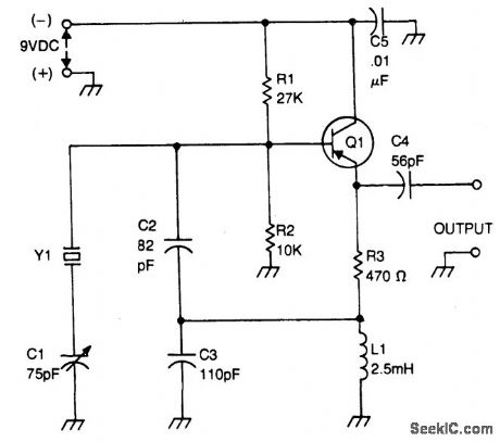

This second example, also from the Internet, shows the correct battery polarity. See you learned something already! Note the + side to ground. In case you failed to memorize this circuit as part of the Extra Exam -- It is a Colpitts Oscillator. The Colpitts always has TWO C's -- one from base to emitter and the other from the Emitter to Ground. They serve as a part of the Barkhausen Criteria where kB=1 and this feedback is sufficient to cause oscillation. C1 enables what is called a VXO (Variable Crystal Oscillator).
The change in the series capacitance C1 works with the internal capacitance and inductance of the Crystal itself to cause the normal oscillating frequency to change by a few percent. Typically the shift is small with lower crystal frequencies changing by maybe 1 or 2 kHz for those less than 10 MHz and crystals above 10 MHz may be changing by as much as 5 or 10 kHz. Certain crystal types are suitable for larger frequency swings. Try to find crystals in the larger cans versus the shorter as they tend to have a greater frequency excursion.

The photo of the transmitter shown earlier uses this schematic. Parts substitution IUWIH. C2 = 100 pF, C3 = 130 pF, L1 = 1mH, Q1 = Ge PNP UHF, R1 = 33K.
I happen to own a $250K CNC milling machine but you can buy one for about the cost of 10 trips to McDonald's takeout and you will have a CNC machine in your shack.
Today I spotted machines on Amazon ranging in price from $179 (lite fare at MickieD's typical of us coasties) to about $390 ( The bill of fare likely to be seen in the Mid-west ). Likely the $350- $390 ones are the more durable and one from SaintSmart is owned by a fellow ham.
Got to the SolderSmoke Blogspot and Click on the Amazon block and search for CNC Milling Machines.
The following were all built on my machine and are easily built on one of the current crop of machines.
Covid19 will be with us for at least another nine months --go buy that machine and build that rig!
73's
Pete N6QW
PS My machine actually cost $3K and it was built by my ME son. The $250K was the bill to send him to college for 5 years.


 |

10M SSB Transceiver --inhaling CW 1/30/2021


