Back to the Simpleceiver Project
Addendum: Graph Paper Layout of the Build
Addendum #2: Data for the J310 and new response plot
Addendum #3: Initial Construction photos PD Board 11/11/2015
Addendum #2: Data for the J310 and new response plot
Addendum #3: Initial Construction photos PD Board 11/11/2015
I must apologize for the diversion to work on the Ten Tec Model 150A. Before picking back up with the Simpleceiver I leave you with this comment: "If you can find a Model 150A --grab it!". Much of the work I did on the Model 150A will find its way into the Simpleceiver project especially the LT Spice simulation work with band pass and low pass filter networks. So while the anxious readers may be grumbling about the diversion --it will benefit you in the end.
Now back to the product detector circuit. We will use the circuit that was simulated earlier in LT Spice but convert this into actual hardware. The final step for the product detector is to mate it with the audio amplifier. The circuit below uses the 2N3819 JFETS but our final configuration is the J310. I do not have the spice simulation constants for the J310 but an A versus B comparison does show that the J310's are "hotter".
Once again the photo below is a GIF since I was given an input that jpg are not as good -- still baffles me why. I encourage the blog readers to download LT Spice and duplicate this circuit. I have added some notes about my experiments and it was most revealing.
Let us start with R4 which is 2.2 K Ohms. This was found by trial and error as entering new values with Spice is easier than doing a lot of hand calculations. A few trial runs will quickly tell "better or worse". What is evident that even 200 ohms or so can make a big difference. I tried 1800 and 2.5K. The value 2.2K seemed optimal.
This next takes us to the source resistor, R1 The spread values used went from 75 Ohms to 200 Ohms. The circuit I originally "lifted' from a publication had the value at 120 Ohms. Now it is obvious why!This experiment is a real lesson about 1) biasing impacts, 2) using specific values of resistance and 3) using 1% resistors. If one used a 20% resistor and cumulatively it was on the low side at or near 100 Ohms the stage gain is down by 6 dB. So this says much about the 1200 bargain resistors shipped from China for $5 --avoid them! The old adage I have a resistor but it is 100 Ohms not 120 Ohms what is the difference --well my friend the difference can be 6 dB!
Next was an evaluation of the impact of the output coupling connected to the Drain of J1. C4, L1 and C6 form a low pass filter to pass frequencies in the audio range. The product detector has two outputs as a result of the mixing process. One output is the difference with our expectation of a 1 KHz signal and the second is sum of the Local Oscillator and the incoming signal. In this case that would be about 14.06 MHz which we want to filter out of the following circuits. I used a 7dBm LO signal (1.414 Volts Peak to Peak) and the input signal at 0.3 microvolts (a typical weak signal). Capacitor C5 coupled the output to the R3 the 10K resistor which in real life is a volume control pot. C5 has impact on this circuit as well.
C4, L1 and C6 impact what is being passed out of the circuit for a fixed value of L1 at 1 milli-Henry (1000 micro-henry). If you make C4 and C4 larger (now at 0.001 Mfd.) this erodes the high frequency response of the network and there is a slight drop in gain in the audio range of 300 to 3000 Hz. C5 on the other hand if it is made larger will extend the lower frequency response well below the 300 Hz. Now these four components are interdependent meaning change one and while upper and lower ranges will shift the overall shape of the response curve may shift the center of the response curve. After several trials in the second photo is the resultant curve. This shows that the curve is fairly flat over the audio range and that the centering is at about 1 kHz. Try it yourself.


Now armed with the circuit values we can make out first run at building the product detector. Mind you we have simulated the circuit first and not soldered one wire or smoked one component. Keep in mind this is a perfect simulation! Don't get your underwear in a knot if you measure everything and get 15.1 dB gain versus 15.3 dB with a 120 Ohms resistor in the source. Now if you got only 5 dB gain then there is something wrong.
I want to take a moment to discuss construction practices and the lack of a specific troubleshooting process. An earlier published project called Let's Build Something (Kuo & Juliano QRP Quarterly Jan and April 2015) uses a modular approach very similar to the Simpleceiver. In fact it has the discrete audio amplifier stage. About a week ago Ben and I got the typical email "Your Circuit Doesn't Work!" Well we know it works because right now that circuit is tacked onto the Simpleceiver prototype and literally hundred have been built. Well long story short --there was a bad solder joint on one of the components and once fixed --we got an email "Your Circuit Works!" Well of course it does! But here is the point:
- Lack of achieved performance has a root cause in the failure to review all of your work before applying power. Look for poor solder joints, wrong connections, no connections (same audio amp stage, different builder, same email message subject as the earlier one, with a photo in which we spotted a missing connection. Duh now it works), look for bad components, or wrong polarities on diodes and transistors, wrong value of components (10K instead of 100 Ohms). Going thru this type of process should be done first and also provides a template of check items if something still does not work. Powering up a circuit without doing a careful check first and finding it doesn't work -- the next step does not involve sending me an email with the subject line "Your circuit does not work".
The LT Spice sets the stage that the circuit does work and so now the problem is on your end! Having a documented trouble shooting process will help your resolve that issue. To that end the LT Spice enables you to look at the waveforms throughout the circuit --if you follow along with your build, it will become apparent the localized problem area. Use the tools that you have and the first tool is not sending me an email.
I hope to build the hardware in the next segment -- but I heartily encourage you to build the LT Spice model. Note I used 50 ohms series resistor with the input signals. By spending time with the model it will help you understand the circuit and how the individual components affect the overall performance. Oh the 2.2K Resistor R2 in the Gate 1 was chosen based on the Solid State Design Manual for the Radio Amateur. W7ZOI states that the Z in is in the range of 2 - 3K. In practice there will need to be matching from 50 Ohms to the 2.2K. This is a 1:44 match and can be done with a ferrite transformer FT-37-43 core with a 3 turn primary and a 20 turn secondary. 3^2 = 9 and 20^2 = 400. 400/9 = 44.4 which is close enough for government work.
Addendum:
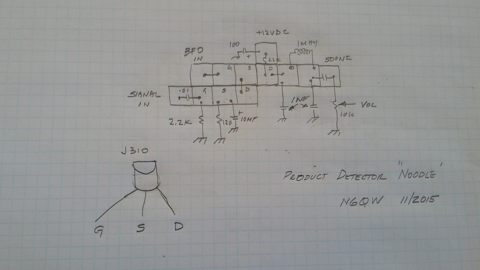
Below is a graph paper layout of how to build the product detector using the island squares.

Addendum #2:
Our friend Nick, G8INE, located the expanded files for the JFETs which can be found on the LT Wiki. Here is the link http://ltwiki.org/?title=Components_Library_and_Circuits and specifically the link to A Large LTspice Folder from Bordodynov” . Now being somewhat skeptical about messing up a good thing when I downloaded the large file I only picked the sub files (libraries) for the JFETS. Next I went into my program files and replaced the original JFET library with the download. That worked really well and I now have significant increase in the number of JFET selections including the J310.
Nick also advised that his noodling with the actual J310 simulation indicated two resistor changes from the 2N3819. R1 is changed from 120 Ohms to 680 Ohms and R4 is changed from 2.2 K to 2.4 K. The device change and resistor changes increases the overall gain by 3 dB -- now we are smoking. Earlier I had mentioned that the J310 is a better device --now you know why! BTW don't forget to amend the parts placement sketch to include the changed values of R1 and r4

Addendum:
Below is a graph paper layout of how to build the product detector using the island squares.
Addendum #2:
Our friend Nick, G8INE, located the expanded files for the JFETs which can be found on the LT Wiki. Here is the link http://ltwiki.org/?title=Components_Library_and_Circuits and specifically the link to A Large LTspice Folder from Bordodynov” . Now being somewhat skeptical about messing up a good thing when I downloaded the large file I only picked the sub files (libraries) for the JFETS. Next I went into my program files and replaced the original JFET library with the download. That worked really well and I now have significant increase in the number of JFET selections including the J310.
Nick also advised that his noodling with the actual J310 simulation indicated two resistor changes from the 2N3819. R1 is changed from 120 Ohms to 680 Ohms and R4 is changed from 2.2 K to 2.4 K. The device change and resistor changes increases the overall gain by 3 dB -- now we are smoking. Earlier I had mentioned that the J310 is a better device --now you know why! BTW don't forget to amend the parts placement sketch to include the changed values of R1 and r4


Addendum #3:
Having the good fortune to own a $250K CNC machine (No the machine only cost $3K, but the $250K is what it cost to send my 3rd son to Mechanical Engineering school so he could learn how to build me a machine) I am able to rapidly crank out boards for my projects. In the photos below I started initially with the layout of just the Product Detector and then added island squares for the BFO. The second and third photos show the build and the location of the second set of squares for the BFO. Each squares is 2/10 of an inch on a side. Somewhat repeating myself --lay out the circuit using graph paper and then transfer the design to the PCB. Later today I hope to mate up the PD with the Audio Amp and LO to see if I can hear anything.


Having the good fortune to own a $250K CNC machine (No the machine only cost $3K, but the $250K is what it cost to send my 3rd son to Mechanical Engineering school so he could learn how to build me a machine) I am able to rapidly crank out boards for my projects. In the photos below I started initially with the layout of just the Product Detector and then added island squares for the BFO. The second and third photos show the build and the location of the second set of squares for the BFO. Each squares is 2/10 of an inch on a side. Somewhat repeating myself --lay out the circuit using graph paper and then transfer the design to the PCB. Later today I hope to mate up the PD with the Audio Amp and LO to see if I can hear anything.


73's
Pete N6QW


