You Tube ~ Power Switch Repair
One of the various known maladies of the KWM-2 (did I also mention it sucks on CW) is the failure of the main power ON OFF switch. When this switch fails you are SOL, and I was in that boat!
[ What you are about to read is a solution to the power switch failure that was successful in large measure because of experience, tribal knowledge, and engineering genes. Having some nifty tools like a manual milling machine was also key. Also, significant in the fix is a well-stocked junk box. Soak in what was done as you, the reader, may have a problem like this one at some time and you can refer back to the N6QW solution.]
In the upper left-hand corner of the KWM-2 and KWM-2A is a four-position selector switch that reads OFF ON NB CAL. It is a standard wafer switch but ganged to the non-round shaft of that switch is a second switch which only operates in going from OFF to ON.
.jpg)
We see this setup typically on Volume controls that also have the Snap Action switch causing the ON OFF action to be built into the control. Thus, the ON OFF switch is piggy backed and integral to the volume control.
Collins took a 3 Amp rated snap action switch and mounted it to a plate assembly and mechanically ganged it to the 4-position selector switch. The snap action switch was made by Oak Industries that no longer is in business and the parts are unobtainable. So, you have to improvise and that is what I did.
Original Oak Switch
Essentially someone else came up with the idea (not an original N6QW idea) of adding a mechanical action via a shaft coupler that operates a volume pot with a switch. The pot is not used, but the switch is. So, the problem is how to mount the pot/switch and how to make it work seamlessly. Those are two key words like a beacon on a lighthouse on a foggy night: work and seamlessly!
A second similar approach as seen on the Collins Collectors Association website, uses a 3 Amp Microswitch that is engaged using a flag like device mounted on the shaft that actuates the lever arm of the Microswitch when moving the selector switch to ON.
My approach uses the pot/switch approach but is different in how it is mounted. As with all thing's homebrew, nothing is easy and simply drops into place. Here are some challenges.
1. The Oak Switch is rated at 3 amps. One possible weak point of the Collins approach is that when the KWM-2 was put into service the line voltage was 110 volts AC and today's standard seems to hover around 120VAC. The MTBF for that switch was likely not seen as 66 years. Most Volume Control/Switch units today, are only rated at 1 amp @125VAC. Problem #1, find a switch that can handle 5 or 6 amps at 125VAC. I found a 5-amp rated switch.
2. There are many mechanical issues in arriving at a solution. One of the 1st problems is the shaft on the four-position wafer switch -- it is not round and how do you install that in the round hole of the coupler? A secondary issue is the shaft coupler is metal, and you must insure it does not touch the ring contact on the 4-position selector switch.

In the sketch above we can see the non-round shaft, the void space with the shaft inside the coupler and an insulation solution using a fiber washer where the inside diameter was increased to 1/4 inch to prevent the metal coupler from touching the selector switch contacts.

Problem Solutions!
The photo above shows the Fiber Washer where the inside diameter was increased to 1/4 inch and is placed on the shaft between the selector switch and the Shaft Coupler. Also in the photo are thin sheet metal strips that were cut so that three pieces on each side of the non-round shaft make for a snug fit and fills the void in the coupler. The installation inside the shaft coupler involved the use of a Dental Mirror and small tweezers. The thinner shiny metal cut down to about 5/16 inch was used for the fill shim pieces. The Fiber Washer on one end and the fully round end of the pot/switch shaft captures the shims so they will stay in place.
[The metal filler installation process is best described with a simple analogy much like having a tryst with a 300-pound YL in the back seat of a 57 VW Beetle. Almost impossible. Not totally impossible, but almost!]

Some Luck!
One thing on the Luck side is that the mounting screws of the 4-position wafer switch were extra-long and provide a piece of the solution. Using some aluminum 4-40 threaded spacers, this provided a means to mount a metal plate at a proper distance from the open shaft end that will house the pot/switch. I was able to use the original OAK switch mounting plate as a template for the new manufactured mounting plate so all would be in alignment.

Spacers and Coupler Installed

Mounting Plate Installed
The Pot/Switch arrived yesterday, but I could see already I need to add a bit more "space" between the coupler and mounting plate. I have some longer spacers so that will be the 1st order of business, before final installation.

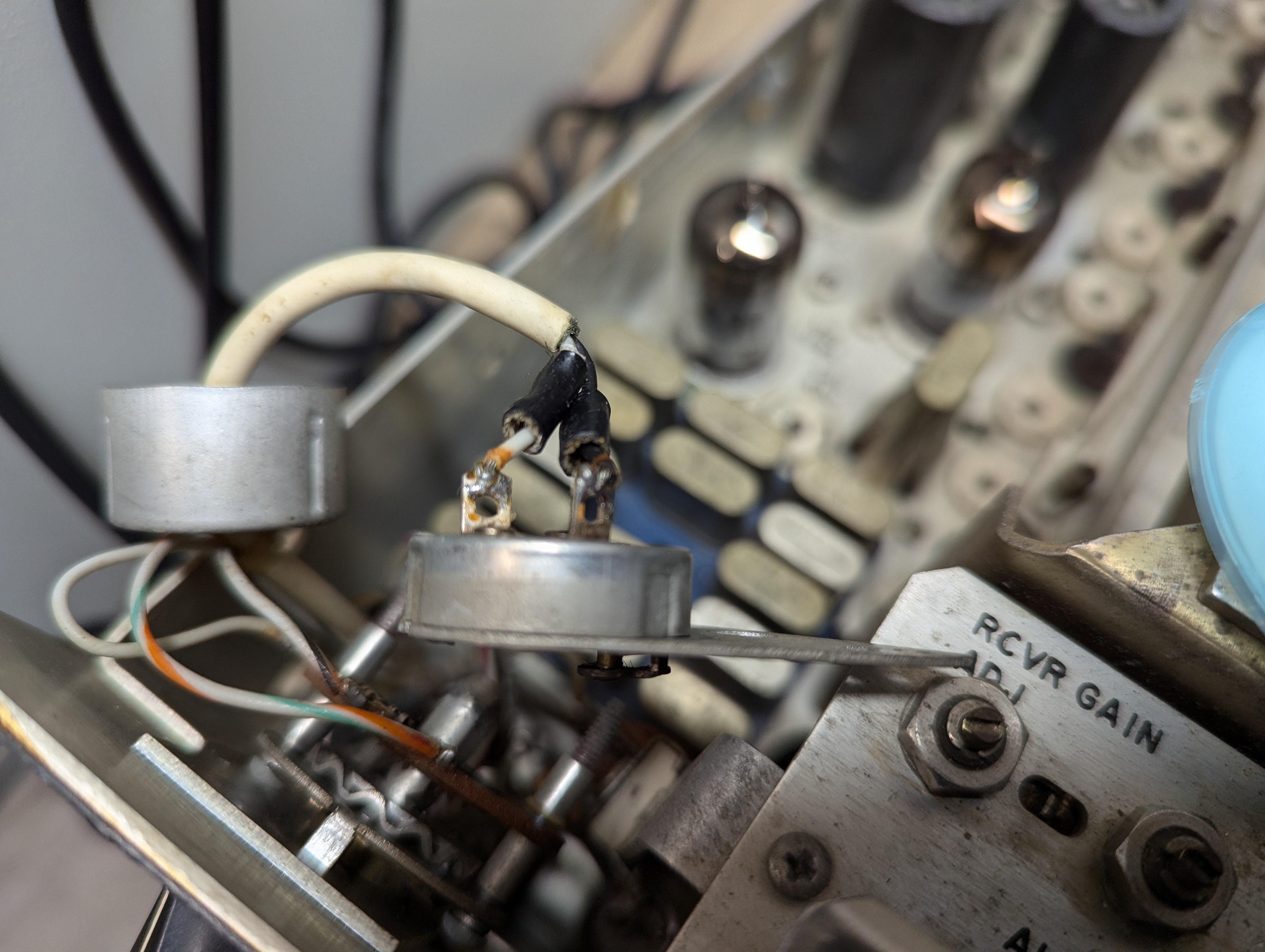
Longer Aluminum spacers and a couple of homebrew washers enabled the mounting plate and the pot to be at the correct position with the 1/4 inch to 1/4-inch coupler. Everything is rock solid! I fabricated a thick round aluminum spacer that has a 3/8-inch diameter hole and is fitted between the mounting plate and the nut securing the pot. Why? The metal plate is thin aluminum and the washer on one side and the pot itself on the back side in essence "stiffen" the mounting plate so that it is rigid.
The lock tab on the pot housing intended to anchor the pot position on the mounting surface, was bent outward and actually rests against one of the mounting screw heads on the back side. So, as you turn the selector switch CW, the tab resting on the nut prevents the pot from moving in the plate. There was no way to drill a hole in the mounting plate without interfering with something. My solution is an added measure.
The switch action is smooth and verified with an Ohm Meter. Move from OFF to ON and the meter goes to Zero!
When You Know, You Can Make It Go!
73's
Pete N6QW


