The MC1496 SSB Transceiver ~ #47
9/21/2020 Added Schematics and Layouts
I had 40673's! This shows J310's as a substitute
It all started with SolderSmoke Podcast #224 and the comment from N2CQR about a transceiver project from Paul, VK3HN. It seems Paul found an assembly at a Radio Rally (hamfest) that was a project in SSDRA pp203-205. This assembly was an IF amp stage (2 X 40673 and Crystal Filter) and a Transmit mixer Stage comprised of the Motorola MC1496 DBM. VK3HN took that assembly and added bits and pieces to create a Four Band Transceiver he called The Prowler.
I was intrigued by that project and started small with a Direct Conversion Receiver using the MC1496. My effort called The Cat-Around (like a left coast Prowler) was but a stepping stone to a full transceiver using the MC1496 in four key locations:
- The Receiver Mixer
- The Balanced Modulator
- The Transmit Mixer
- The Product Detector
The Balanced Modulator and Product Detector circuits were a direct lift form the Motorola Application Notes. I used the schematic for the Transmit Mixer Portion as found in SSDRA for both the Receive Mixer and Transmit Mixer. The IF Module used the 40673's and the GQRP Club 9 MHz Crystal Filter.
You can literally use any 9 MHz Filter including the INRAD Model #351 which will be back in Stock on October 1. The IF Module Schematic matches the Zin/out with 510 Ohm Resistors. the Zin/out of the INRAD is 200 ohms so you will need to match to that impedance like a 2.5 to 1 match. A 5 Turn to 8 Turn Ferrite transformer would get you close 5^2 = 25 and 8^2 = 64. 64/25 = 2.56:1.
A truncated Block Diagram of just the modules mentioned would look like this...
Our Board would be rounded out with a 2N3904 Microphone Amplifier and combo 2N3904/LM386 for the Audio Amplifier.
This is the 1st transmitter test of the MC1496 Balanced Modulator and Transmit Mixer.
The MC1496 SSB Transceiver has been set up for two bands including 40 and 20 Meters. A simple DPDT Toggle Switch signals the Arduino to change bands (1/2 the switch) while powering on (2nd half) banks of relays two switch the BPF and LPF Networks.
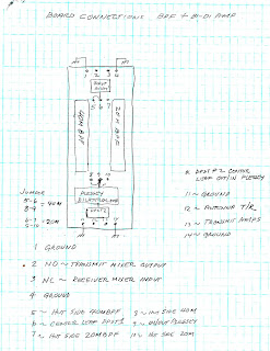
I always consider any rig I build as an experimenter's platform and this rig was no exception! I have used the bilateral Plessey Amplifier in many of my projects; but typically in the IF Module. This time I thought why can this be used as the Receiver RF Amp (in one direction) and Transmit Pre-Driver (in the other direction). Essentially the 2N2907 is the Rx RF Amp and the MPS6514 is the Tx Pre-Driver. (This is another experiment and a change from the 2N3906 and 2N3904)
The board photo above is the two BPF's, the Plessey Circuit and the In/Out relays. Initially I used three pin headers with shorting bar to switch bands. This board has now been upgraded to include two more relays (in the open space) so that band switching is all automatic from the front panel. Once again the Plessey circuit comes through!
Some would ask why are you using 1970's technology to build a rig. Well it was an experiment for me and I have shown it can be done. The cost is pretty small and most importantly --Because I can!
73's
Pete N6QW
TLPD!


