The Next Project... A 2022 Transceiver.
10/10/2022 My Apologies.
10/05/2022 Still Alive!
Regrettably my caregiver duties have overtaken any free time so not much progress. But I am hopeful yet this week I will cut at least one board. A PSA from N6QW.
Think of it like Mary Jo has a "crink" in her back and unable to get in the backseat of the 57 VW Beetle. A bit of a setback but not forever.
Seems like the hired caregiver had a small emergency and not able to come for a few days so there is that crink in the plan and I am the sub-altern.
Pete N6QW
10/02/2022 Two Homebrew Projects from N2CQR and KK4DAS
Two close friends and associates Bill, N2CQR, and Dean, KK4DAS, are engaged in several related and connected projects. The first is a PTO (Permeability Tuned Oscillator) and the second is a Direct Conversion Receiver employing the PTO.
Some might argue sure this is like building a one transistor transmitter --everyone has done that, but I would argue that is not a good or even great analogy.
PTOs were used in the past in high end Analog VFO's such as those found in Collins equipment, most of the Drake radios and even Ten Tec radios prior to digital generation. Now there is some argument whether what was built is true PTO or is it PTO like.
Back to basics and the PTO. I repaired a Collins PTO as found in a KWM-1 and it was a marvel of engineering. In a "standard" Analog VFO there is a variable capacitor that tuned the oscillator to various frequencies with the range of the capacitor travel. The PTO uses fixed capacitance but moves a ferrite core (as in the case of the Collins, Drake and Ten Tec) driven by a fine threaded screw into a coil. Because of the thread arrangement and degree of travel per revolution the inductance can change in a very linear manner.
This results in a linear dial reading that can be accurately repeated. Now Collins did a bit of sleight of hand in that they limited the travel distance to 200 kHz over the most linear part of the coil. Drake and Ten Tec went 500 kHz.
Heathkit had their own version called an LMO (Linear Master Oscillator).
The work done by Bill and Dean was an offshoot of the latest Farhan Analog transceiver rig that employs the PTO like principle. The hang up for the purists is that the current PTO uses a brass screw to vary the inductance not a ferrite core so that the permeability is not really being changed but the inductance is, so you have a variable frequency change with a screw adjustment.
The other key piece is that to hand build a PTO is a huge mechanical challenge as there must be mechanical rigidity and a means of "holding the screw" so it will travel seamlessly through the core -- no jerky movements or you have frequency jumping. Enter technology and 3D printing. The whole PTO assembly was 3D printed so that fabrication of a PTO like assembly is a piece of cake. Bill on his blog has fully documented his amazing DCR build https://soldersmoke.blogspot.com
The next piece is to employ that PTO in a Direct Conversion Receiver. Dean and Bill have been pursuing a parallel track with such a build and once again you must really listen to a DCR to understand the comment that the signal has presence.
There is a significant import to what my friends are doing. It is planting the seeds and fostering the growth of a home constructed project that is usable on the ham bands today! Yes, you can do it!
I have not built the PTO and neither do I have a 3D printer but a recent check of Amazon shows that one can get a 3D printer for less than the cost of a $300 CNC Mill. Thusly, I think the technology rich low-cost fabrication tools (3D Printer and CNC Mill) suddenly remove some huge obstacles to taking on a home brew rig. You can do it.
Now time to toot my own horn -- I don't screw with PTO's (other than repair/rebuild) or LC VFO's but about two years ago did build a DCR with an Arduino/Si5351 and can attest to how really good it sounds. For those who take SPRAT my DCR was a subject of an article. I received 105 requests for the code -- so likely others have found out how good a DCR sounds. The Part III Video especially points out the presence in both the CW and SSB portions of the band. It is like hearing HiFi or getting Mary Jo in the back seat of the 57 VW Beetle.
Now a Thought --suppose you build two DCR's with the LO supplied 90 degrees out of phase and ran the outputs of the mixer stages into two separate audio amplifiers -- is that the makings of binaural reception? Haven't really thought that through but that lash up is close to what I use for my SDR Peashooter transceiver. This would require further evaluation as a simple phase shift on CW & AM would not be so much of an issue as on SSB where you would be copying two different sidebands but the station at the other end is transmitting only on one sideband. Again, more noodling before you could say this would work. Important -- it causes one to think.

Be sure to visit N2CQR's Blog and see the work he has done. This is a great foundation for taking on larger projects but yet with this simple build provides a very usable and useful project to the shack.
Pete N6QW
9/30/2022 While I steal time to build the 2022 Radio, some filler subjects.
I have many parallel interests and my websites are evidence to that point. Also on the front burner is Homebrew SDR rigs. For many years I have used the Raspberry Pi or the ASUS Tinker Board as the computer of choice to run my SDR rigs but for many a trip to the world of Linux is a trip too far.
There are many software suites that can transition both the Linux and Windows Worlds. QUISK is one of those although I find the use of the Windows QUISK to be "klunky" (a variant of kludge). There are other software programs that are Windows only like HDSDR.
Thusly for your dining and dancing pleasure yesterday I took a few minutes to configure a Windows 7 (Starter) Net Book to run HDSDR. Here is a short video of that lash up running my Peashooter SDR.
9/29/2022 A Data Point
I had mentioned that I used the design of an earlier radio as a reference for the 2022 build. Here is a shot of the top board from that earlier radio and more importantly the case size for that radio is just about the same size as our Cookie Tin.

Note the Arduino/Si5351 in the top LH Corner, the IRF510 in the top RH Corner and the Bidirectional RF Amp/Tx Pre-Driver in the lower LH Corner and the Driver stage in the lower RH Corner. There will be some device changes but basically the real estate is there.
Now so far this project has all been on paper and thus we now need to move into some actual hardware fabrication. The Soldering Iron has been rusting and that is key because my process forces me to look at what it takes to build a rig so that the painting into a corner episode is minimized.
One well known ham and you tube star disagrees with me as the 1st thing that person does is start soldering circuits. I suspect he uses a lot of solder as my process subscribes to measure twice and cut once.
The next several weeks will be boring as I try to steal time from my caregiver duties to CNC Mill the boards and fabricate the hardware. Another critical factor is my project sequencing approach and the 1st item on the list was the Digital LO/BFO and that is done.
So, there will not be much to see for a short period. But I plan to keep blogging on a second side hustle project and will come back to the 2022 project as completing the 1st board will result in a working receiver.
This is akin to getting Mary Jo into the back seat of the 57 VW Beetle and what follows will be the best part.
Note the https://www.n6qw.com has an updated pdf of this blog through 9/27/2022 -- it is 82 pages. For those who have to have paper -- get a ream of paper and some new ink cartridges!
9/28/2022 The 2nd CNC Board.
When you have built over 50 SSB transceivers there is more than a slight possibility that you have a baseline of work that simply can be brought forward to the current project.
In looking over what I have documented, a rig comes to mind that had the stacked boards and the top board had the Arduino/Si5351, a steered RF Amp/Tx Pre-Driver, the Driver and the Final Amp all on a 4X6 inch board.
BTW I just did a backup of my project files, and it is a staggering 200 GB. I think there is something like 50,000 files in the project directory. One of my tribal knowledge points -- keep good files and back them up!

This photo above has the 4 blocks with the lower left-hand block soon to have the Driver stage installed and the lower right is the Final Amp. The LPF and T/R is off board and there were shields installed after the build. Under the board a 1/8-inch aluminum plate was installed which is the heat sink for the final amp.
This looks like a great place to start the 2nd Board development process. Yes, having a CNC Mill makes for an easy task to create boards like that above. I just checked and many are available at Amazon for under $300.
See https://www.n6qw.com/CNCMILL.html This is a primer about CNC Mills.
9/27/2022 Where to Start the CNC Design?

The P3ST Mainboard
- The P3ST Board was 4 X 6 inches and now I have to go back to the Cookie Tin and determine the size of a board I can shoehorn into the tin. I think the 6-inch dimension is OK, but the 4 inch may be a wee too tight.
- The 2nd task is look at the real estate of what is labeled "1st IF Amp" as this area is now both the Post Mixer Amp plus the 1st IF Amp. This might require adding a few more columns to the pads. Or it might be enough space as is. How we resolve that is to use a piece of graph paper and to add the circuit components to see if a layout can be made within the space confines. We also need a peek at the IF Filter Space to see if the G4CFY filter fits in the open area.
.jpg)
P3ST Main Board.
9/26/2022 The Boards for CNC Millings
I hope to start laying out the boards for CNC Milling, so you won't see much change in the postings for several days so keep checking back. Hard to show anything when you have nothing to show.
This is unlike Mary Jo in the back seat of the 57 VW Beetle -- a lot to see.
9/24/2022 The Digital LO/BFO Build!


An Updated PDF version of the posts through 9/23 is located on a link at https://www.n6qw.com
9/23/2022 Tribal Digital LO/BFO Knowledge.
Yesterday I had a round of emails on a related subject and thought this might be a good subject for the current blog project.
So, what choices do you have for the actual fabrication?
Immediately when you mention a VFO and construction practices -- my mind regrettably drifts back to the dark days of Analog VFO's and how the Mechanical Construction was a significant factor of whether or not your VFO drifted like Mary Jo after two drinks or remained on frequency. Surely, we always need to exercise appropriate and proper fabrication methodologies, but there is not so much concern about the mechanical aspect in digital builds as you are stuck with if pursuing the dark side Analog VFO's.
For the most part until you hit the Output Ports on the Si5351 breakout board, all signals are digital! This opens a huge hole on what you can do during the fabrication stages, circuit layout and the methodologies employed.
Some approaches I have used include the use of:
- Sockets for the Arduino Nano and Si5351 which is huge if you are prone to smoking parts. Blow a Nano or Si5351 simply remove the item from the socket and replace with a new device. The signals are mostly digital and for the output side you can use the SMA connectors usually supplied with the Si5351 boards. Soldering to the Si5351 pads is acceptable -- but again smoke a part and it is more than simply unscrewing a SMA connector. The sockets are easily used with perforated board, and this offers great flexibility. I have even used single sided copper vector board where the top side of the board is a terrific ground plane. Before inserting the sockets into the single side copper vector board take a 1/8-inch drill bit and ream out the holes a bit so there is no possibility of a socket pin to ground plane short.
- Wire wrapping a popular technique of the past, but also a curse if you are prone to smoking parts as you literally have to unwrap all of the connections and opportunities abound for making an error.
- PC Boards. If you are adept at creating Gerber files, then having boards made in China is pretty painless. I do not like this method where you directly solder the device to the board as it is an issue if you are prone to smoking parts. Unsoldering some 30 pads that are the size of a pin head is incompatible with my FFS. (Fat Finger Syndrome)
- Manhattan construction is not a good alternative unless you use something like boards from W1REX. The 1/10-inch pin spacing is hard to do with pads that are 0.2-inch square. You will have a mess on your hands.
- SMD parts again with the Manhattan approach is difficult with the pin spacing. The use of carrier boards does alleviate part of the problem. MPJA (Marlin P Jones Associates) has some great deals on Carrier Boards.
A short recap -- Digital is less critical on the fabrication as is required with the Analog build. There are many options for the actual build with sockets being the most flexible if you smoke a lot of parts. Perforated board allows moving of the pieces to achieve a compact layout.
9/22/2022 Some Typical Digital BFO/LO Builds.


9/20/2022 Part #2 Wire List
Below is the "wire list" for the Arduino Nano (or any Arduino). This is more or less another standard I have adopted. It sure makes for easy trouble shooting as I have memorized the pins and so when tracing a circuit, I know by rote which pin is which pin and where it connects. This happens to be the wire list for the P3ST but will work for the 2022 SSB Transceiver.
Function | Pin | Comments |
|---|---|---|
Encoder a | D2 | I use a Bourns 24 PPR PEC Series Encoder 100K MTBF |
Encoder B | D3 | |
Ground | GND | |
Step | A3 | Sets the step size from 10 Hz to 100kHz ~ Momentary PB |
VFO A | D4 | Two Frequencies Select with default startup of 14.2 MHz |
VFO B | D5 | Default FT-8 startup Frequency 14.074 MHz (Alt use a different band like 40M) |
USB/LSB | A1 | Normally USB on 20M. |
TUNE Tone | A2 | A Ten Second Pulsed 988Hz Tone is initiated with this Pin ~ Momentary PB |
Tone Out | D6 | A Square Wave output (Needs RC Filtering for a Sine Wave ) |
LED | 3.3V | This is the wiring for the ST7735 128X160 Color TFT Display |
SCK | D13 | Using other displays like the ILI9341 is a Different Pin Out and needs |
SDA | D11 | the ILI9341 Library |
AO | D9 | |
RESET | D8 | |
CS | D10 | |
GND | GND | |
SDA | A4 | This is the Wiring for the Si5351 PLL Clock Generator |
SCL | A5 | Clock 0 is the Local Oscillator Output |
+5VDC | +5VDC | Clock 2 is the Beat Frequency Oscillator Output |
GND | GND |
9/19/2022 Digital LO/BFO
The critical path item for the project is the Digital LO/BFO! This is the heart of the rig and if you are still fooling around with Analog VFO's this is the time to jump into the modern world.
One of the initial stumbling blocks was the software and that is no longer an issue. There are tons of sketches available, and I freely supply my "kluge work" to anyone who requests the information. You cannot beat the accuracy and stability of the modern electronics.
The device of choice is the Arduino Nano and the Si5351. Add in a Bourns Mechanical Encoder along with a nice Color TFT and you are there. Some bonus features are Selectable Sidebands and the generation of a Tune Tone.
Of benefit is I have adopted a standard process for building the Digital LO/BFO inclusive of a 9 VDC on board regulator, sockets for the Arduino and Si-5351 and finally pin header sockets for plugging in the Color TFT, the Encoder and the associated controls.
Thusly the next several posts will focus on the Digital LO/BFO. Time to step out of the past and into the future. You can do it!
9/18/2022 Project Recap
9/17/2022 Top Board Layout

9/16/2022 Board Layouts

9/15/2022 Crystal Filter Matching

9/14/2022 Some of the Final Pieces


9/13/2022 More Details on the 2022 project.
(Many of the new project circuits were used in the P3ST project and have worked well. Again, no hardware as such has been built for the 2022 project.)


9/12/2022 A Few More Circuits.

I subscribe to if it is not broken, then don't fix it. Two of my go to circuits are the RF Driver and the Final Amplifier. For the Driver I use the 2N2219A and there is very practical reason for this that being it works and is less expensive than the 2N3866 or the 2N5109. Another really big reason -- it is modeled in LT Spice! In case you didn't know the 2N2222A and the 2N2219A are identical in characteristics save for the larger die area of the 2N2219A which results in a higher device dissipation.


9/11/2022 More Thoughts About the Final Build.
Eventually what is built will have to be fitted inside of Mrs. Fields (The Cookie Tin). Rookie Mistake -- thinking about that after all is built! So, the time to do that is before the 1st board is fabricated.
I have great success using stacked boards and that seems like a good template. In addition, great thought must be given to servicing.
A short story about the replication of a Wes Hayward project and servicing issues. If you are fortunate enough to own the premiere W7ZOI publication SSDRA, you can see his competition grade CW receiver project. I built that receiver with the addition of putting every circuit module in an aluminum mini-box. There are no way external signals could get into that receiver other than through the antenna port. That worked well.
What didn't work well was when there was a problem every circuit was inaccessible. It was impossible to put a scope probe on various circuit elements -- a really bad idea. You had to disassemble the whole receiver just to find the problem. Lesson learned.
Additional considerations are heat, especially with the RD06HHF1 and another the I/O ports. My prior experience with this highlights a path where the front panel includes functionalities typically found on the back panel. Thusly front panel real estate is divided into the high rent and low rent districts. Ergonomics plays a vital role in the placement of various controls. I have fat fingers so teensy knobs are not in the scheme of things.
Yet another consideration is that the Cookie Tin is small so once set up how do you make it stay put on the operating location. Hint: Velcro!
Again, we have built none of the hardware, but all of the items mentioned so far are impactful to the actual hardware fabrication.
Just so there are changing pictures on the blog -- included today is the Microphone Amp as used in the P3ST.


Having a new photo on the blog with each posting is sort of like blog reader flypaper -- it is an attracting device.
As Clemenza says: "Ditch the Gun and Grab the Cannoli!"
9/10/2022 A Paper Built Rig, So Far
Up to now no actual hardware has been built but most of the work has been analytical with great deference to LT Spice. But I do think it is time to start the work on the block diagram and to also specify some open blocks.

9/09/2022 The Post Mixer Amplifier
Using the ADE-1 there is a conversion loss of around 6 to 7 dB as defined by the manufacturer. The Post Mixer Amplifier is intended to null the effect of the conversion loss while providing a bit of a signal boost. So, if we looked at something in the range of 10dB that would offset the loss plus add about 3 dB of gain. In our original gain distribution, we had pegged the Post Mixer Amp at 20 dB. A later look gave me pause that perhaps is too much gain for that stage.
But our IF stages can pump out a few extra dB per stage and so that then would become a zero-sum game.
I have a preliminary Broad Band design with the thought here that there would be different IF frequencies based on a builder's choice and therefore this amp would become universal. The 10dB Gain figure is over the range 3 to 15 MHz, the typical range of Crystal Filters. Note L1 is 7 Turns of #26 on a FT-37-43 Core.


Clemenza Says: "Ditch the gun and grab the Cannoli"!
9/08/2022 A Broad Band Amplifier
Before we leave the 1st IF Amplifier/3dB stage, I should mention that a similar amp stage, 2nd IF, would be used following the Crystal Filter. Luckily such a stage would need to have a 50 Ohm output suitable for driving either the 50 Ohm Port of a DBM on the Product Detector or the 50 Ohm Port of the Transmit Mixer. Now you will have to match from your Crystal Filter to the input to the 2nd IF which is 50 Ohms.
Using the process from the earlier post you can translate C1, C2 and L1 to your favorite filter frequency. I would avoid a homebrew filter especially if you have never built one before. The arcane methodology of the Dishal filters is best left to others if again you are new to constructing filters.
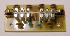
Do not believe that you simply slap 4 crystals in a circuit add the 5 coupling caps and you are there. You are not! You can purchase 9 MHz commercial especially high-quality filters from Spectrum Comms in the UK. (Owner G4CFY)
http://www.spectrumcomms.co.uk/
We will need a Broad Band Amplifier for the RF stage and I have noodled out something which will give you about 10 dB gain out to 10 Meters.
The goal of this stage is to provide a flat response across the HF bands. I purposefully set the input signal level to 0.5 Microvolts which is more in the range of signals picked off of your questionable antenna (a lead connected to a plastic rain gutter) or a chunk of wire laying on the shack floor.

The blue line is the input signal level which I assume is being loaded by the input as the frequency increases. The Green line is the signal output across 50 Ohms. That is a flat response and the spread between the in/out is 10 dB over 30 MHz.

Up to this point we have the IF amplifier stages, the 3dB Pad and the receiver RF Amplifier. In many of my projects this stage was made to be steerable so that on Receive it was the RF Amplifier stage but on transmit it was the Transmit Pre-Driver stage and there is no reason why this could not be employed as well for that purpose.
Here is a plot with the input changed from 0.5 microvolt to 500 Millivolts and the 10 dB gain holds across the HF Bands.

9/07/2022 A 9MHz Amplifier with 3dB Pad. Using Capacitive Matching.


9/06/2022 A look at some of the circuits!
I purposefully have not shared a block diagram as this is the Fan Dancer effect. You look and for the longest time all you see is Fans, but you have your suspicions and hope soon to catch a glimpse.
One circuit element identified in our Gain Block assignment, well actually two pieces are the 1st IF amp stage and the -3dB pad. So, what would such a circuit look like? This is where LT Spice comes home to roost -- you do know that was mentioned early on as a tool.


Clemenza says: "Ditch the gun and grab the cannoli"! Thank You Richard Castellano!
9/05/2022 What is 100 dB System Gain?
If we arbitrarily suggest a 100 dB System Gain across the Receiver, just what does that mean? A standard often used is S9 and that relates to a signal of 50 microvolts. The simple view is a signal picked off the air at 50 microvolts with a 100 dB System Gain would register 5 volts at the end of that system. You can do the math where 100 dB = 20 * (log (5/0.000050)). That is a healthy increase in signal level. [5 Volts (RMS) across 50 Ohms is 500 milliwatts --just for reference purposes.]
I took a notional look at a 100 dB Gain Distribution across a Receiver, and this is only one cut of what may be required to deliver 5 volts from a 50-microvolt signal.


- A Receiver is a combination of circuits that take weak signals traveling through the ionosphere and reproduces them into useful information
- The key to the received signal is that it is faithfully reproduced without loss of information
- The receiver circuits do not compromise the original signal.
- Passive mixers. It is so cool to use Double Balanced Mixers like the ADE-1 or SBL-1 or even the TUF-1. No DC voltage is required and typically just four connections: IF, RF, LO and Ground. But they all suffer from a Conversion Loss, which may be on the order of 6 to 7 dB.
- Crytal Filters. These too can have loss and I typically peg that in the 5 to 7 dB range. Although a friend built a 10-pole filter, and his measurements indicate only a 2 dB loss. That may not be typical!
- Impedance matching. If we fail to match the In's and Out's there will be losses. This also extends to matching across a range of frequencies. Broad Band is not a YL Orchestra but indeed a flat response across a wide frequency range.
- Band Pass Filters. If the design employs Band Pass filters and they are not carefully designed then there may be a peak in the middle of the band but a rapid drop off at the ends, A flat response across a band of frequencies is a design issue.
- Internally generated noise. Yes, that gets down to things like packaged audio amplifiers and active mixers (NE602). These can be noisy and if there is noise then there is a signal loss!
9/03/2022 ~ The Overall Gain of the Receiver Section.
First Rule: Turn off the Soldering Iron as having a hot iron with nothing to solder is simply a distraction!
Think of the famous line from the movie "The Godfather". Paulie Gatto was rubbed out and Clemenza says to his associate "Leave the Gun and Take the Cannoli". So, I say to you "Leave the Soldering Iron OFF and do the noodling"! BTW my mother's family name was Gatto.
You could slap dash together a bunch of circuits, hopefully no Bitx, no TIA or no EMRFD and what would you have? It might work but is it working well! Too early to declare victory!
It is best to start with an overall gain distribution for the entire Receiver section and then look at the stage gain (and losses) of the individual receiver blocks. Often a lot of gain is put in the 1st RF Amplifier stage and indeed you will boost the signal BUT you will also boost the noise so that spells compromise and moderation.
Then there are endearing terms such as "Dynamic Range" which factors in the ability of the receiver to amplify both weak and strong signals. If in the stages following the RF Amp stage, you arrange the gain to boost the weak signals -- the very strong signal blast through the remainder of the circuitry. That is why Volume Controls and sophisticated AGC circuits were invented.
We also need to pay attention to the minimum discernable signal (MDS) that the receiver can hear. In the receivers of old we find that the published sensitivity factors often said that you simply didn't hear that weak DX stations.
Then there are issues with internally generated noise -- you know the poor LM386 that just seems bloody awful noisy. You spent a lot of time on the front end to end up sabotaging the project with a noisy audio stage.
For this posting we have not gone into the depths of the overall gain and only mentioned some of the factors involved in making the design decisions for the topology. In time we will flesh out the myriad of those factors. We also hope to establish an overall gain design goal. (Some say 100 dB while others say 200 dB -- but we hope to peg that number. You got to think hard and long about 200 dB and how do you prevent it from becoming an audio oscillator.)
It is not enough to just build a radio! But the real joy is to build a radio that hears well and works well on todays' modern bands. The emphasis on the hearing part applies to most hams as we do a lot more listening than we do transmitting. To wit that applies to the majority of hams as well who spend time working contests! The DX'ers of course do a lot of listening! For those of us who are homebrewer's, the listening part is a test of our design!
While we are "noodling" stage of the project, if you want to participate in this adventure then this is a good time to engage yourself with LT Spice. This project may actually cause a surge in the use of the Nano VNA if you feel comfortable in trusting that device. A good quality DSO and a solid Signal Generator are some basic tools also needed.
*******
This project will start from the back end and usually an afterthought in most projects. I have a neat small metal box that originally held a food product. So now the challenge is how to build a SSB transceiver inside the confines of this box.

As typical I have requirements list of features and functionalities. It has to have a Digital VFO, Color TFT and that is a starter. It will mostly be transistors and the band of choice will be 20M. After all the Cycle 25 is supposed to be so spectacular.
But hidden in my noodling process for this rather small transceiver is DFMA (Designed for Manufacturing and Assembly). I have built rigs that once done were really hard to service. By starting with this premise will affect how it is designed, how it is built and how it is assembled.
Then the focus immediately turns to topology. It has to be something that is not the usual cookie cutter approach where you start with Bitx circuits then add TIA circuits and finally only stuff from EMRFD. This is time to think out of the box. Yes, No analog VFO!
Regrettably you will have to know stuff to replicate this rig. Yes, you will have to learn something other than the Menu listing from an ICOM IC-7300. Are you up to the challenge?
Pete, N6QW


