The Diode Doubler
The Innovative Trick!
Some 13 years ago I was really busy cranking out articles for QRP Quarterly. The Direct Conversion Receiver project appeared in the Winter 2012 issue.
That said, embedded in this project are not one but TWO options on how to build the LO for the DCR. Of import is that what is shown is how to take a lower frequency (more stable) LO and transport that signal to say 40 or 20Meters.
Friend Bill, N2CQR, has seen an uptick of mail to his blog regarding homebrewing rigs. Just this morning Bill answered an email where he suggested for the Transmitter either the 10 Minute Transmitter or the Michigan Mighty Mite. For a Receiver he suggested the High School DCR. Presented here today is a DCR with some options for the LC VFO (LO).
Start by looking at the dial scale I made that shows a fairly accurate and linear LO. The calibration chart was made using Excel and the readings were taken using an HP Counter I had. (80 MHz and Nixie tubes).
There are two schematics for the LO where one is a two band version and the main tuning range is on 75M. Enter the Diode Doubler Circuit that is used to double the Frequency from 75M to 40M. That is the schematic that has the Title Block Dual Gate MOSFET. Pin Jumpers are show on the schematic to enable switching between 75 and 40M. A nice and simple band switch. That feature was skipped in the hardware photo as who in the hell does 80M CW or SSB. One of the requisites, today, to work 80M SSB is that you start the cocktail hour at 9AM and wear a red ball cap.
Just below the Doubler is a schematic of very innovative trick from Lew McCoy and was presented in QST when it used to be a technical publication and not a catalog of foreign made ham gear.
So, McCoy's trick is to take a Dual Gate MOSFET a BF998 (Get those from Todd K7TFC.) and Gate #1 is a Crystal Oscillator operating at 11 MHz. The Output from a Varactor tuned 75M VFO is impressed onto Gate #2. The BF998 is a mixer stage and the subtractive mix (11 - 3.9 = 7.1 MHz) is fed to a 7 MHz Band Pass Filter and onto the DCR. This combo as the additive mix 11 + 3.9 = 14.9 which is above the 20M Band and filtered out by the BPF.
The second harmonic of the VFO is at 7.8 MHz and above. If you are anal retentive and worry about the BPF not catching this you can put in a W3NQN Low Pass Filter ahead of Gate #2 and then you are sure the 2nd Harmonic of the VFO is down by 100 dB. However since the Receiver only tuned from 7.0 to 7.120 MHz -- you would not normally hear that signal above 7.8 MHz. BUT that would be a concern for any use in a transmitter, thus the W3NQN filter system.
I used what I had in the junk box, but if you moved the Varactor Tuned Oscillator to 4.9 MHz and the crystal to 12 MHz then the subtractive mix is 7.1 MHz and the additive mix = 16.9 MHz. This combo then would not need the W3NQN filter. Note the 2nd Harmonic of the Varactor Tuned Oscillator is at 9.8 MHz.
This is another Tribal Knowledge Trick (TKT) and you saw it from N6QW. Open your mind to the possibilities for moving the DCR to other bands!
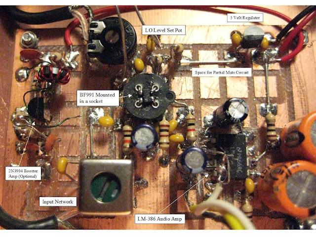
How do you mount those Teensy Tiny BF991's or BF998's. (Wait for it another TKT.) One simple answer is a 4 pin transistor socket. Every time I trim the leads on a through hole component I save the cut off leads. So the mounting involves four cut leads that are inserted into the transistor socket and then bent over at a right angle, The bent over piece is trimmed so that there is about an 1/8 of an inch left and the leads are arranged pointing inward to form the ends of a Figure X.
The tips are tinned and then with a pair of tweezers (and a steady hand) the X leads are aligned with device. Touch the pin and the tinned lead and instant connection. When you arrange the socket on the board the FAT Pin on the DGM is the Source and it should be installed on the lower right hand side of the X. One of the above photos shows a socket with a BF991.
This is an earlier (by 10 years) variant of the MC1496 DCR and it worked very well. But the two LO Schemes are no match today for an Arduino and Si5351.
But we want to recognize that the Seeed Xiao RP2040 or Arduino plus Si5351 is not everyone's cup of tea. Today however for those of the LC VFO persuasion, you were given some options that add to using your Glue Stick PTO (high school DCR project) on other frequencies.
73's
Pete N6QW


