In the Soldersmoke Podcast #250, I mentioned the W3TLN 20M QRP SSB Transceiver that appeared in an issue of the ARRL Sideband Handbook. It was then I realized I only had one volume of that publication. A tour through eBay found me a different volume in quite good condition for $8. Buy it Now and Done!
Many of the projects are the same in this version just purchased as the version I have but a new one for me was the "IMP TR" shown below. W4IMP in 1960 created a SSB transmitter using only 3 tubes and was dubbed the IMP. A solid-state version of the tube IMP appeared in the December 1961 QST and thence the 1965 version of the Sideband Handbook.

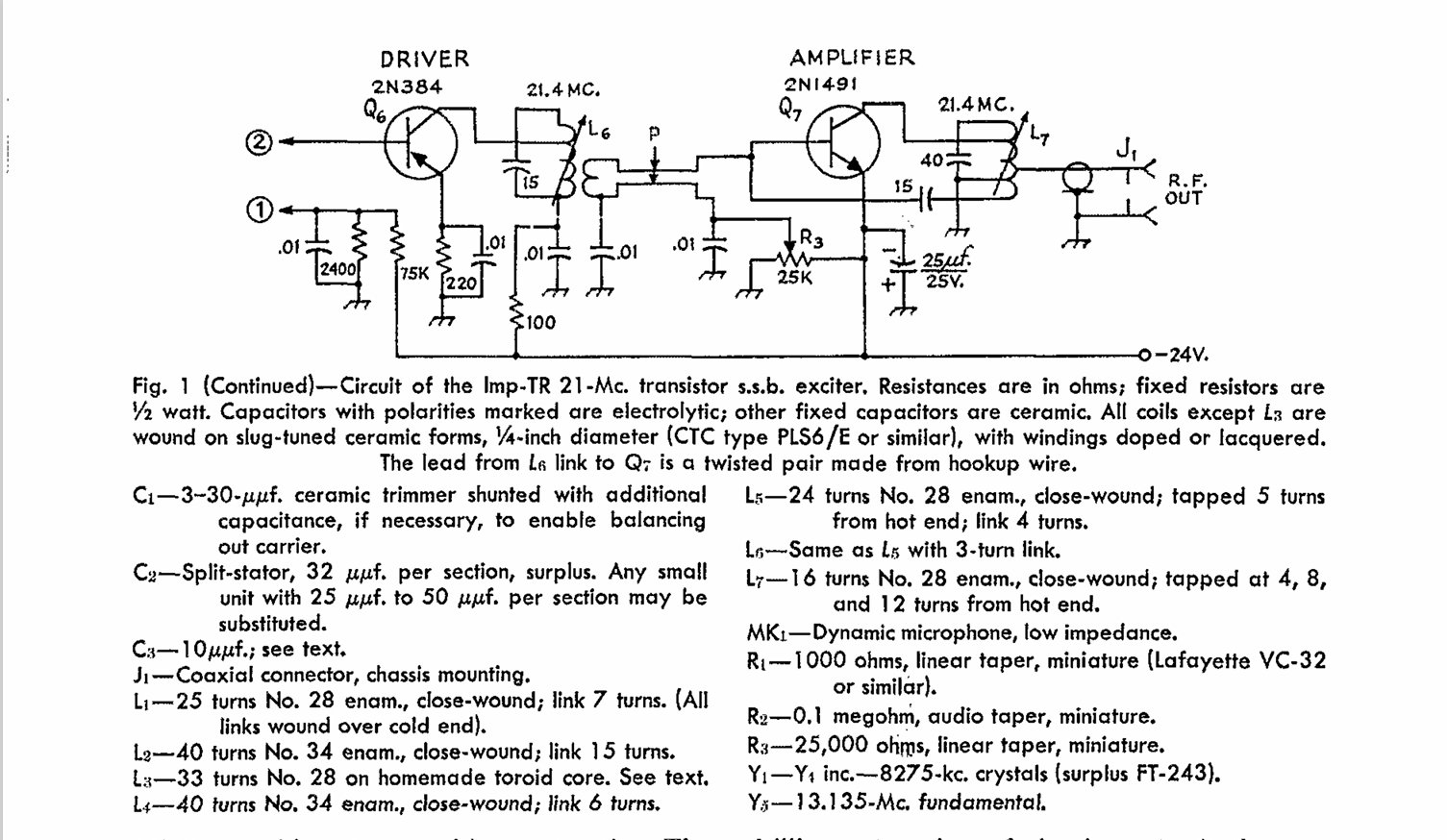
The "IMP TR" from December 1961 QST
This would be a cool project to easily replicate today some 60 years later. Well maybe just a little difficult to do. His filter was made from FT-243 surplus crystals where he opened up the cases and shifted the frequency of several so that they would provide the necessary band width.
This old technique called "rubbering" involved using an HB Lead pencil to mark the crystal wafer so it would oscillate at a lower frequency. Or to pull out the crystal wafer and using a piece of glass with wet Comet Cleanser to grind down the wafer thus raising its frequency. A shot in the dark at best! This is like using a Nano VNA uncalibrated and never having read the instructions for its use.
To make this easier to build, the circuit should be modified to take a 4-pole ladder type filter where you have a chance of building something with today's components and use readily available filter software.
But while you are at it, I also see the possibility of making some modifications so that it could be used as a Receiver and transforming the IMP TR into a SSB Transceiver. The Magic comes from Diode Steering where you can add the new filter AND give rise to a transceiver.

A Receive mixer would inject a signal into L4 back feeding the 4-pole filter and the two diodes in the Balanced Modulator would act like a Product Detector to an audio amp stage. It would be a little more complex than that, but this is a notional starting place. This is not unlike was done in the SBE-33 transceiver.

Above is a new PNP Microphone Amp circuit that would feed the winding on L2 on transmit. Using diode steering would only supply a microphone signal to C3 on Transmit. On Receive more diode steering would connect to an identical circuit but at C1 where the circuit is an audio pre-amp stage. Again, just a 1st paper noodling of possibilities.
The Supply voltage would have to be changed so that power is normally supplied to the Receive circuits but on TR it would switch to those circuits only used for Transmit. R7 could be a pot to adjust the Mic Gain off of the wiper.
Look at the 2N1491 which was the "hot" RF Device in 1961 -- maybe a watt or two out at 14MHz. The price was like maybe $30. Also note the hybrid nature of combining PNP and NPN devices. It seems strange to be putting -24VDC on an Emitter and to Ground the Collector.
The bottom line is that some of these older projects have possibilities for a current update. Some concerns I would have been if the filter alone would provide enough gain to make this work without some amplification in the filter module. I also see the possibility of replacing the 2N384 with a homebrew Double Balanced Mixer stage at the L4 juncture as this would provide both the receive and transmit mixing.
This is like the TV Show "Extreme Makeovers" where all you have left before you start the rebuild is a bare piece of ground.
Hats off to W4IMP whose day job I believe was dentistry. Indeed, he left a huge watermark on homebrewing in the early 1960's.
73's
Pete N6QW


