As homebrewers we have choices for the circuit topologies of the individual elements we use in our projects. You know things like the Balanced Modulator or Final Amplifier. Often it is not so much the circuit itself but the guy. We have all said this is what W1FB used, or Wes used this in such a such project or this came from Farhan. Or on a much, much smaller scale I saw this on the N6QW website.
Recently I saw a very good thing happen in the ham homebrew community. Hams are Pogo Sticking from simple Direct Conversion Receivers to DCR Transceivers and then to DSB Transceivers and soon Filter or Phasing SSB rigs.
So, OK you are lost but what I want to cover today (at 4AM) is the situation exemplified by the W1FB Tuna Tin Two. Some forty years ago (maybe 50) Doug created a Two Transistor CW Transmitter project. It was a huge success, and I suppose thousands of replicas were built. Later on, the ARRL had to issue a revision to the project as it needed a harmonic filter on the output stage to comply with the FCC regulations on spectral purity. So, if you built the original circuit without knowing about the Final Filter you are in non-compliance today.
Now let's Pogo Stick to Balanced Modulators that are on the path from a simple DCR to a SSB Transceiver. We have the Two Diode (Farhan Bitx20 and Doug), the MC1496 (Wes in the 20M SSB QRP Dec89/Jan90 QST) and the Diode Ring (typically the ADE-1 or homebrew from many).
Often the choice of topology is driven by the number of parts and no more so than comparing a Two Diode to a MC1496. We tend to skip over (or glaze over) the performance (and compliance) factor. Yes, the MC1496 is better and has compliance aspects not achievable with the Two Diode "simple" circuit and it does use an IC and more parts.
Thusly, we move to a comparison of the Two Diode, Single Balanced Mixer to the Diode Ring Double Balanced Mixer.
Single Balanced Mixer/Modulator
If the output signal contains either the modulating signal or the carrier signal along with desired modulated signal and the other is suppressed, then such mixer/modulator is called a single balanced mixer. An example of such a mixer is a Two Diode Single Balanced Mixer.

Graphically above we can see the Two Diode Single Balanced Mixer has four outputs at the fundamental that include the two DSB components RF-LO and RF+LO. But also riding along is the LO and the RF.
Double Balanced Mixer/Modulator
A double balanced mixer/modulator is one that suppresses both the modulating signal and carrier signal at the output. An example this type of mixer is a Double Balanced Diode Ring Mixer.
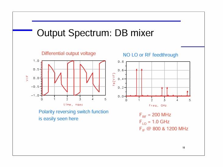
For our Double Balanced Mixer (Diode Ring), on the right Graphic we can see RF-LO and RF+LO, but no LO or RF Feedthrough.
You often see the Two Diode Single Balanced Mixer in the Bitx20 Modulator circuit. The Double Balanced Mixer is also seen in Balanced Modulator circuits with both homebrew and commercial units like the ADE-1, the SBL-1, TUF-1 and of course the MC1496.
Basically, the Two Diode Single Balanced Mixer has extra products in the output (LO and RF). This could be an issue and needs careful evaluation as not only do you get the desired output but quite possibly the Modulating Signal or Carrier riding along to give you grief. This is especially serious if a harmonic of one of these extraneous signals slips through a downstream Band Pass Filter
Personally, I would not use the Two Diode circuit. Just because it was used in a popular rig does not qualify it is a good engineering solution in all cases. Stick with the Diode Ring Mixer and move on knowing the only products coming out of the diode ring are the ones you want.
That is an issue with homebrewing where you pick a circuit to use because it was published somewhere by a "guy" (like Wes, Doug, Farhan) without fully understanding that some weird signal riding along on your primary signal may be because of the topology you used. To repeat myself, I personally would not choose the Two Diode Single Balanced Mixer for use in a homebrew rig. Then again, I don't use LC Oscillators as there are better choices with no drift!
DE MINIMIS You need to learn this Latin Phrase as it is the root cause of why what you bought from China a week ago and is enroute to you will not show up on your doorstep. Basically, that phrase means "small stuff" and those types of items formerly sailed through the customs process with no tariff. As of Feb1 that has been rescinded. So basically, those treasures, (you know those circuit boards you had made) are in the system with an uncertain outcome. Hey MAGA-O-Lytes -- you did that! I almost suggested buying a CNC Mill as a workaround to de minimis for circuit boards, but now those have a hefty tariff -- yep, those come from China too.
Them that know can make it go.
73's
Pete N6QW


