No matter how much you enjoy gluing your fingers together by using ugly construction and through hole parts, the end is near for this type of homebrew!
The demise will happen to you sooner rather than later as the parts suppliers will force you there. Right now, offshore suppliers likely have two lines for the same part with one being through hole and the other for Surface Mount.
It won't take the bean counters very long to show the business case for only one product line -- Surface Mount Devices (SMD). This is already in play with many of our favorite parts like the ADE-1 and the BFR106.
Yes, there will be some boutique manufacturers who will continue to make through hole parts but at prices only a few can afford. A true niche market but unaffordable. The 300B vacuum tube is available today but you need a home loan to buy one.
So instead of making all the usual excuses, why not shift to starting an SMD project. Here is the rub -- it will take you from your comfort zone, as SMD will not only force the use of parts you can hardly see but your construction methodology will indeed change.
My 1st foray into a radio that had extensive deployment of SMD technology was the LBS II which was a second generation build of the Let's Build Something project only using SMD techniques. That was almost 10 years ago in 2015. Yes, it was a QRP Quarterly Article in October 2015.

The thrust behind the LBS II was the size. I sort of marveled that the LBS was actually a very solid N6QW design but mine was mounted on a board 2' x 2'. Kind of hard to fit that in your shirt pocket.
Size Matters!


The two Boards are the Before and After. In the lower right-hand corner is the Mic Amp shown today. The Audio Pre-Amp is directly above it -- same circuit.


Taking on an SMD project was an excellent exercise for me as it gave me an insight in what was needed to be done to make SMD successful. An example -- we think nothing when using through hole parts of taking our SIGLENT 200MHz Digital Storage Oscilloscopes (DSO) and clipping on to a resistor or capacitor for test purposes.
Not so easy to do with SMD. So now I add a small lead stub at a critical junction so you can clip on to that as a test point. Yet another trick is the tombstone cap. I simply take a 10nF SMD cap and solder it vertically to a pad, so it looks like a tombstone but provides a test point.
The Key with SMD is to start with a small project where not many parts are involved yet is a useful circuit. The small project is a skill and confidence builder.
Single transistors used as audio amplifiers are a great starting point. The next circuit can be used as a standalone Microphone Amplifier or as an Audio Pre-Amplifier stage driving a LM-380N-8 Audio Integrated Circuit.
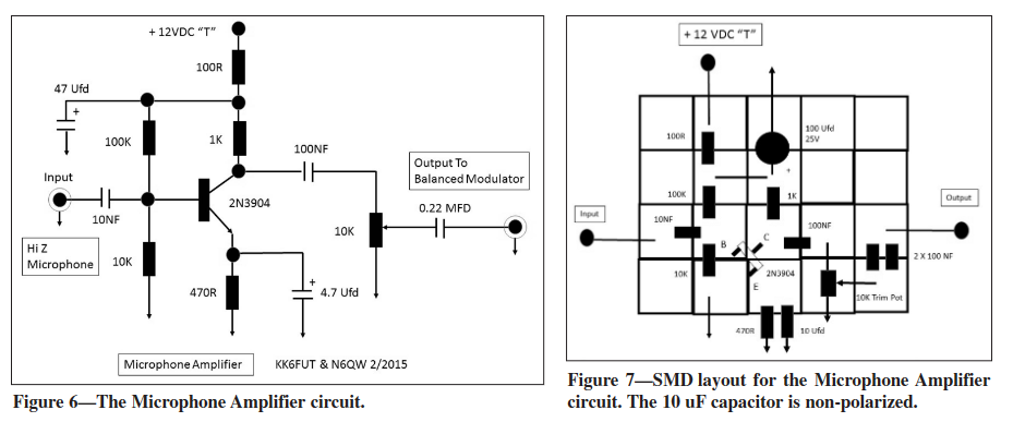
On the left we have the schematic and on the right a SMD version using my Island Squares approach. I have a CNC so creating these small squares is just punching the start button using a stored program. But you can purchase a built pad of squares from W1REX.
BTW check the LT Spice simulation below as I have improved the circuit constants for the 2N3904 Audio Amp stage. The output is flat from about 300 Hz to 60kHz. R6 is normally a 10K pot.


You must prepare for SMD in several critical areas. The first is have a proper workstation with good lighting and room to spread out the parts and tools.
Speaking of tools, you will need some tweezers, a head band magnifier and a temperature-controlled soldering iron suited for SMD work. That, my friend, is not an 80-watt job bought at Radio Shack as a part of a going out of business sale.
One excellent tool is a cookie tray about 9X12. Slip a piece of white typing paper in the tray and then put your circuit board on top of the white paper. The tray catches the flying parts and the white background highlights black parts that jumped off their pads.
Another preparation is to search You Tube videos that give tutorials on how to solder SMD parts.
Give yourself a break! SMD parts come in various sizes and initially opt for the 1206 size which are big SMD parts. The 0408 size are almost impossible to see. Also, when ordering resistors pay attention to the wattage. For most solid-state circuits, we use the 1/4-watt resistors which are adequate. Many SMD resistors are only rated for 1/10 watt or less. I found this out the hard way on the LBS II. I did install some underrated resistors and we had the mushroom cloud extravaganza.
You also must take a technique from our military snipers where control of breathing is critical. I have learned to hold my breath when I make the 1st application of solder to a part. The size of the solder is also critical and no RoHS solder --it won't stick. Get the thinnest size you can find from Jeff Bezos (Amazon).
You are being given some sage advice and that is if you want to continue "brewing your own" the methodology and parts are shifting to a different form. We see that already in that the new good stuff is in SMD.
This is not simply bending the feeler wires to find cans with no labels on a fast moving can line but a new detection method to catch all of the cans without a label. [A reference to an earlier post about finding cans of soup without a label on a production line.]
The W1REX small pads will work for most applications but soon you will need to think about a small CNC mill to make circuit boards. Mills can be found on Amazon for less than $200.
I am looking at you the blog readers and see those who are saying I have a large stock of leaded 2N3904's so I am good. That very likely is true if you only want to build a single design from old. But if you want to venture out and build new designs then likely that stock of 2N3904's is woefully inadequate.
Time to learn something new!
73's
Pete N6QW


