Assembling the Beam ~ Mosley MP-32-N
(Information added on 9/13/2015)
(Information Added on 9/14/2015)
(Information Added 9/15/2015 ~ Project temporarily stopped because of Rain)
(Information added on 9/16/2015)
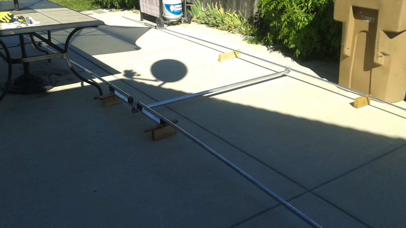
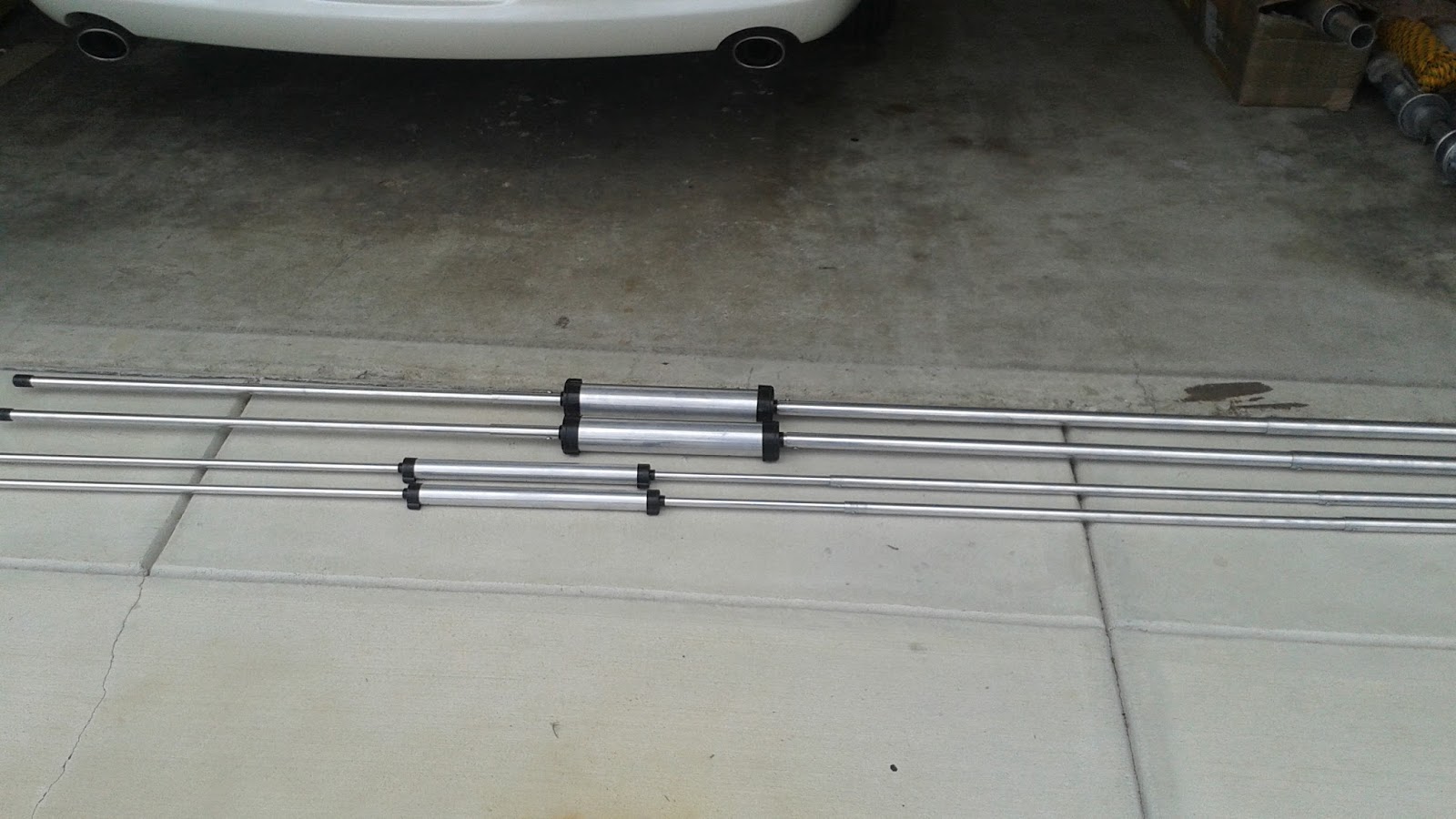
Since it was raining out I took the opportunity to assemble the beam elements and would like to report the following.
I essentially assembled the two driven element sub-assemblies as well as the two sections of the reflector. In the final assembly of the reflector these two section fit inside a 6 foot long center tube that has two 1/4 inch holes closely spaced in the center of this section. Ultimately a U bolt clamps the reflector to the boom by passing through this section.
The two reflector subassemblies fit within this center tube and there is significant overlap (almost three feet on each end). In the final configuration the reflector subassembly ends have 1/4 inch holes align with the two closely spaced 1/4 inch holes and a U bolt which grasps the boom passes through a support block and through the aligned holes. While the tubing for the reflector is of a lesser diameter the center tube with significant overlap of the reflector sub-assemblies makes for a structurally solid assembly.
There is a good deal of clever engineering in how the beam is constructed and assembled. Yes I did put the anti-corrosion compound on the joints and that did make the telescoping much easier. There is a note that certain of the holes that are drilled were not de-burred at the factory and that is left to the customer. Because of the tight fit of the telescoping sections it is imperative that the holes are "clean".
The form, fit and function are superb. All holes aligned perfectly and all the hardware was present. There is slightly different hardware for the MP-32-N because the driven element is larger than the driven element for the TA-32-Jr-N thus the BOM is slightly different but well covered on the addendum page for the MP-32-N.
I have made an inquiry to Mosley about fabricating a small L bracket that would be attached to one of the set of holes used for holding the driven element to the boom. My intent would be to mount a bulkhead SO-239 Coax Connector on the L Bracket and then route the beam connections to this coax connector. Then the coax cable could be simply screwed on to the bulkhead connector and the whole assembly taped with coax seal. The factory install of the coax is to peel back 6 to 8 inches of the braid and put terminal lugs on the braid and center conductor. I would be concerned about water intrusion into the coax.
We are still about a week away from the final hoisting of the beam but we are certainly closer.
Pete N6QW
Back to the Beam Installation.
I spoke to a Mosley technical person on 9/14/2015 and my several question were answered. Seems like I was sent an old (older) instruction manual and most of my questions are answered in the new manual.
There are pre-drilled holes for all pieces including the Phone and CW settings.
Penatrox should be applied sparingly
A choke balun IS a good idea 5 Turns, six inches in diameter rolled up like a garden hose and the coax can be taped to the boom.
There is already a hole in the boom to mast bracket to pin that assembly to the mast BUT it is not recommended. The reason and the same applies to not pinning the elements to the boom based on any wind load greater than 80 MPH would transfer that energy to the tower or mast. By being somewhat free to move --the theory is it is easier to straighten out the element. beam, boom alignment versus fixing a tower or mast.
The driven element (because a reflector is used and not a director) is the front of the beam.
I took a short break from installing the new beam antenna principally because it was just too hot in Southern California where we had several days this past week with temperatures hitting 100 Degrees F. The forecast indicates a cooling down to the high 70's so back to the beam installation.
The beam I chose is manufactured by Mosley Electronics located in Union, Missouri. Yes guys something actually made in America but the Aluminum probably came from offshore --but that is OK. The specific model I chose is a non-standard catalog item called the MP-32-N.
Basically the antenna is a TA-32 Jr. N by design but is a hybrid in that the driven element is from a TA-32 (legal limit) beam and the reflector is from the TA-32 Jr. In its original configuration the TA-32 Jr. is good for maybe around 1 KW PEP. But with the driven element from the TA-32, the custom hybrid MP-32-N can do the legal limit. Thus I can use my 3CPX1500 A7 homebrew linear amp with this antenna. You can see the difference in the size of the traps with the Jr traps being like 1" in diameter and the legal limit being like 2" in diameter. (These may not be the actual sizes but are stated only to give a relative feel of the size differences.)
Being a two element beam, its forward gain is only about 3 DB on 20M but does have a decent FB ratio of 20 DB. With a less than six foot boom and weighing around 20 pounds it is the best compromise for the mast being used, the footprint on the roof and the neighborhood aesthetics. Having the ability to rotate the beam is another desirable feature even though it is a puny 3 DB gain.
Here Comes the Ranting!
The beam arrived over a week ago; but given our crappy weather it just sat in the box until yesterday when I got around to opening the box. The MP-32-N came very well packed and it survived the trip to SoCal in fine fashion. The first thing I did was to retrieve the Instruction/Assembly Manual and the scant 4 pages quickly told me that this was going to be somewhat problematic. I did not look at the hardware in detail but wanted to start with the manual to see if it was clear what needed to be done. Well having lived in Missouri for about 11 years (not too far from Union) I know that there is a lot of local resident tribal knowledge about how mechanical things get assembled. But not everyone has those mechanical assembly gene's flowing through their bodies --including me. So here is what I see from just reading the manual.
For ease of assembly parts are color coded. Red is used for the driven element and those with a yellow mark are for the reflector. That is good -- but in my case I will use the parts with a blue marking since the MP-32-N has a driven element from the TA-32. In any event color is good.
The actual assembly instructions (Tab A into Slot B) are on a single sheet of the four pages and there is an exploded assembly view which links the parts in the assembly pictorial with a Bill Of Material parts list. There is a special insert for assembly of the MP-32-N driven element as the baseline instructions are for the TA-32 Jr. N and the driven element of course is from the TA-32. That part is OK
The first hiccup involves the single sheet of the assembly instructions which tells you Tab A into slot B, and the pictorial of the assembly sequence. The single page instruction is absolutely silent about the use of the anti-corrosion compound (Penatrox). A note in the lower right hand corner of the pictorial drawing says you must use this compound or the pieces will not telescope and evidently over time corrosion will impact the electrical conductivity of the beam elements. The note is easy to miss.
Once again I have not actually touched the beam hardware but want to use the instructions as a first step to assure myself that it is absolutely clear what needs to be done. On the page which contains the BOM there is a dimensional sketch which shows the final length of the beam elements for what is called condition II -- these condition relate to whether you set the beam to favor the CW portions of the band or the phone portions. Obviously favoring the CW portion would make the elements longer and the drawing shows the dimensions for SSB and notes that about 10.5 inches would need to be added for the CW centering. I gather there may be predrilled holes that let you do this; as there is a notation that there are sets of holes on the driven element traps to enable this. While there is mention about adjustment on the reflector for the CW band, again I am not certain there are predrilled holes.
In the assembly of the driven element there is a caution on the drawing about attaching the terminal lugs to the driven element and then soldering the coax as the material that holds the driven element ends. This insulator material is obviously plastic and you will melt the insulator if you try to solder the coax with the terminal installed on the insulator. That is understood. But if you install the terminal lugs on the coax, can the installation of the coax be done later or is the assembly sequence such that you must install the coax mid process and thus you have this lump of wire hanging out all over the place. The instructions almost lead you to believe that.
Speaking of the coax there are no instructions how to route the coax from the connection point away from the beam like looping the coax over the end of the beam and then taping the coax to the boom Should some sort of coax seal be place over the mechanical connection to the driven element? If there is effort to use Penatrox on the aluminum connections, what about these two connections to the driven element? The instructions emphatically state 52 Ohm coax must be used but are silent about any sort of 1:1 choke balun. Needed or not?
The instructions are silent about "what points what" on the beam direction. In other words if it is a driven element and a reflector combination, is the "front" of the beam the driven element and the back the reflector. Were it a driven element and a director then it follows is the back of the beam the driven element. But nothing is said.
Having had two beams previously (both Hy-Gain, one a 2 element and the other a Tri-Band) there is the ever present problem that because "U Bolts" are used to hold the elements to the boom and the boom to the mast adapter that there will be a subsequent alignment problem within the same plane or that the beam remains in a horizontal plane. A further concern is that the beam rotates around the mast to a position different than originally established. The point here is that there should be either some specification that establishes the proper amount of tightening (torque) to prevent any of these situations or that a mechanical solution is available. I intend to drill at least one hole in the boom to mast base plate so that a pin can be installed to firmly affix the boom to mast bracket to my mast. For the two elements I will assure sufficient torque on the U bolts to firmly hold the elements from moving on the boom while not permanently compressing (depressing) the metal tubes. At the very least Mosley could mentions these issues so that the builder is aware of the possibilities of these events occurring. Yes Mosley -- this might mean 5 pages in your instruction/assembly manual.
Too bad there is not some intermediate setting between CW and phone. Sure would appreciate hearing from anyone who has a TA-32 Jr. N and their experience with this product.
n6qwham@gmail.com. 73. Pete N6QW