Yesterday I received an email from Jim up in 7 land inquiring about some Arduino sketches and problems compiling the sketch. I think some of the code was provided by me. I too at times have noted some issues with sketches that previously complied "slick as anything" but then started to hiccup.
Has any one heard about Arduino code that may contain viruses?
Pete N6QW
SS Podcast #210 we talked about the Vintage Sideband Roundtable ~ at any minute smoke and flames can come from an old boat anchor. It is true!
Try this with your uBitx!
Pete N6QW
Just can't leave well enough alone! #4
Search this blog for the Simpleceiver and you can see the painful detail on how to build one. The other day I was thinking about the original Simpleceiver and how that I still had most of the prototype boards still screwed down to a chunk of wood. Frankly I was OK with the 12.096 MHz crystal filter but still felt it has some short comings. So then I thought about popping in a 9 MHz GQRP Club Filter in the IF stage and that caused me to revisit the IF amp design and what it takes to move it down to 9 MHz which is the filter Cf. A bit of digression as it was on this very prototype board that I came up with the single pass relay switched amplifier approach. Essentially the signal passes in a single direction through the IF Amp Block and on receive the signals coming from the Mixer Stage (SBL-1) are passed through the IF amp Block on to an ADE-1 which is now the Product Detector. With two relays and a bit of coax on transmit the ADE-1 is now the Balanced Modulator and its output is relay switched to the input side of the IF Block Amplifier stage and the Output Side which is now SSB is relay switched to the SBL-1 which is now the transmit mixer stage. There is no switching of the LO and BFO --just relay steering of the signals through the IF Amp Block Stage to always pass in a single direction. The 12.096 MHz IF Amp block had just a few changes to resonate the tank circuit to 9 MHz. The 5.13 uHy inductor is made with a T-68-2 (Red Core) and has 30 turns of #24 enamel wire. The 400 pF is a 180 and 220 caps in parallel. Following the 2dB pad is a 6T to 19T matching transformer on a FT-37-43 Core (#26 enamel) as this matches 50 Ohms to 500 Ohms which is the Filter Zin. On the output of the filter is a 9T to 19T matching transformer to match the Z out (500 Ohms) to the input which is 2.2K [9^2 = 81 and 19^2 = 361. 361 / 81 = 4.45. 2.2K/500 = 4.4. Close enough for government work. ] I needed a bidirectional amp stage ahead of the Band Pass Filter with one half being the receive RF amp and the other half the Transmit Pre-Driver. I had a board I made that was designed for the AG30386G MMIC amp and so I used that approach. Just as easily I could have used another J310 stage with relays to do the same job but opted for the MMIC stage since I had the board and the devices. The transmit driver is the standard 2N3904/2N3866 from EMRFD and the final is the IRF510. The Mic amp and Audio Amp were already on the prototype board (2N3904 for the Mic Amp and the Audio Amp is the NE5534 and LM380). I have now switched over to a newer (and better) mic amp design which now gives a flat response from 250 Hertz to over 10 kHz. The console to the left is to be replaced as it was just pressed into service to get the project "hot on the air". The replacement is shown in the third photo.
-
Yes a real kluge --but works --several QSO's so far including one running 600 watts! You have to love those GQRP Filters. 73's Pete N6QW
So OK I have a lot of transceivers that I have collected with most being acquired on the cheap. So while there may be many, the invested dollars are relatively low. Periodically I will drag one out of the storage bin and try to fix the unit. This is done more so as a technical challenge; but often I drive myself nuts in the process.
Here is a recent example. Several years ago I bought a Ten Tec Triton IV Model 544 which is the digital version of the Model 540. Several years ago I actually converted a 540 to a 544 and you can see that on my QRZ page. It was also a subject of an article that appeared in QRP Quarterly. Thus I have a bit of background with this very FB Ten Tec rig.
The Model 544 I have supposedly was hit by lightning and was inoperative. Well that was true; but not a total disaster. (That is why I got it so cheap.) Replacing two back to back diodes that were shorted ahead of the reed relay that disconnects the receiver during transmit cured one of the problems and a new set of finals cured the other major problem. The rig is now operational.
BUT and the Big BUT the display does not stay fixed on frequency. You get that annoying drift of a few hundred cycles and the ever flickering last digit over time. Guys it is still an Analog PTO with a digital readout. That had to get fixed.
Most if not all Ten Tec rigs have an accessory socket where you can add an external VFO and the Model 544 has that functionality. This is where you laugh a bit … on the back panel is an octal tube socket fitted with a jumper plug. [Octal tube sockets and solid state rigs -LOL]
The stock configuration brings the LO signal to Pin 8 where it is physically connected to pins 6 and 7. The theory is that with these three pins connected, the transmitter and receiver are on the same frequency. With an external VFO connected to pins 6, 7 and 8, then a switching arrangement in the remote VFO enables:
Transceiver operation on the remote VFO
Transceiver operation on the Model 544
Receive on the Model 544 and transmit on the remote VFO
Transmit on the Model 544 and receive on the remote VFO
Thus my plan was to essentially uncouple the internal LO which has various ranges depending on the band. The basic PTO operates in the range of 5 to 5.5 MHz and that is used directly on 20 Meters. For the other bands the PTO is mixed with various crystal frequencies to produce LO signals in various ranges from 5 to 19 MHz for injection into receiver and transmitter mixer stages.
I have a band switched Arduino/Si5351 that I simply programmed to match the ranges of the LO for each band. You can even do this with an AD9850 as you only need the LO as you retain the BFO built into the Model 544.
Now you don't even need a display on the Arduino/Si5351. By injecting the proper LO frequency and having the band switch on the Model 544 set to the right band, the internal Model 544 displays the frequencies just like when the PTO was in the loop.
I was joyous as the only modification to the Model 544 was to unsolder the Jumper wire connected to Pin 8 on the external plug. There is no messing with the radio innards.
In fact if you can locate a non-functional 8 pin tube just remove the tube itself and use the base as a new plug. If you go this route then you can do some amazing things like separate the receive and transmit frequencies. My LO sketch includes two VFO's so now you have even greater capabilities.
I made all of the connections (one) and my plan worked. I could tune all of the bands and better yet Ten Tec had an auxiliary band switch to cover the four ranges on 10 Meters. I can do it with just one 10 meter range.
You do the tuning on the remote VFO but the Model 544 does all of the displaying. What is also nice is that I can manually change the step tuning rate which is nice when you want to QSY across the whole band. The one thing I have not resolved is the offset tuning --not a major issue just something not done as yet.
So I am listening on the various bands and I do happen to have a display on my remote VFO assembly. The Arduino/Color TFT is reading 16200800 and the Model 544 is reading 7.200.8 (with the 8 being a Green LED). Then it happened the last LED on the Model 544 starts to 'flicker up/down" but my Arduino/Color TFT which has a greater resolution is rock solid.
So what conclusions can you draw from this?
Something else aside from the PTO and the Crystal mixing circuit for the various bands is at work.
There is a crystal clock in the internal Model 544 LED display board. It may have some issues and therefore is causing a shift in the time base.
The BFO frequency is summed with the LO in the display circuitry so that the BFO is added or subtracted from the LO depending on the band. The IF is at 9 MHz and thus the LO runs in the 12.5 to 13.0 MHz range for 80 meters. (Subtraction LO-IF.) Whereas the LO runs in the 12.0 to 12.5 MHz Range for 15 Meters (LO + IF). Possibly there are some issues with the circuit that mixes the LO and BFO for the display.
In an earlier Model 544 that I owned there was a problem with the ua723 voltage regulator that had to be replaced and that cured a frequency jumping problem. I did initially replace the 723 regulator as it did have a frequency jumping problem; but that did not resolve the flicker.
So the concept of a remote VFO is doable with a minimum (and reversible) modification to the Model 544 and this should work for other rigs like the Drake TR-4 or Yaesu FT101 both of which can have remote VFO's. I did something similar to this with an Atlas 210X --so lots of possibilities for updating the older boat anchors.
If you want the code send me an email to n6qwham@gmail.com.
If you have any ideas about the flickering send me an email to the above address.
Calling all Junk Boxes, N6QW is looking for a part!
Recently I bought an SBE-33 SSB Transceiver for $52.30 and have been doing some major restorations, which principally involved a great deal of capacitor replacements. I did have to replace the speaker which was blown; but had an exact replacement taken from a Junker unit.
I have had the rig on the air and so far I am impressed at the 1963 technology --even with an analog VFO. Yesterday running my SB-200 I worked Croatia, 9A5W, Nikola on 40 Meters. That is a big first for me and I got a notable report of how good it sounded.
A short story --- the dial markings are at every 5 kHz and a ham running a FLEX5000 contacted me to tell me I sounded bad and was not on frequency (7.208 MHz). I asked that he give me some chatter wherein I zero beat him. Then when I transmitted back at him inquired about the signal. He said I don't know what you did but you fixed it. You are now on frequency and the audio is clear. Wow --he has been a ham for 5 years and well I will stop there.
The Junker SBE-33 has provided many mechanical parts that were missing (the speaker of course and mostly shields although I did have to fabricate one of the shields). Should mention all the transistors are original save for one and I think I have that one too. Look up the specs on a Philco 2N1727 just for fun. It is now mostly stock and I am down to one item -- The Panel Meter.
It is blown and I attempted to repair it but can't get it loose from the case. Thus the only option is to find a replacement meter. Not any meter but one that came from an SBE-33. I guess blowing the meter was a problem, as the Junker is minus the meter too.
So if you have an SBE-33 sitting gathering dust in your garage, here is your chance to move it elsewhere. I need just the meter but will take a whole rig. Please advise price and shipping to 91320. I can be reached at n6qwham@gmail.com.
73's
Pete N6QW
3/11/2019
Arduino: How to add the CW capability!
It is always best to turn off the soldering iron first (and to also know which is the "hot" end) and go through a bit of a noodling process to actually think about what you want to do.
Firstly we need to take a look at the Pin Count. If you are using one of the really neat Color TFT displays as I have in many of my rigs you have taken up quite a few of the Arduino Pins. At this point you might want to start looking at an Arduino Mega 2560. Having 54 digital pins will not constrain you on inputs/outputs and the 16 Analog Pins is also a bonus. If you will be using say a 20X4 LCD then the use of the I2C buss frees up a lot of digital pins and opens up the possibilities for using a Pro-mini or a Nano. Overall size of your rig may force a smaller physical size microcontroller. Depending on how much you want to display you might even get by with an 8X2 LCD. When I documented my Bitx40 build which was fabricated just before the Raduino was added, I used an 8X2. You can see that on my website at www.n6qw.com.
So from a Pin Count and for the normal SSB operation we have the encoder and step select ( 4 pins including ground). The I2C Buss (4 pins, but two are 5 VDC and Gnd). USB/LSB Select (one pin), VFO A/B Select ( one pin) and TUNE (one pin). True not all are digital pins, as five of those use Analog Pins 1 through 5. So we still have lots of Digital Pins to work with using the Uno, Nano or Pro-Mini.
Functions we are looking to add to the Arduino: the very first is to have a switch ( 1 pin) that says check if this pin is active and if so go to the CW routine. The very 1st item on the list is to shift the BFO to USB for CW Receive.
Because we are using the Arduino we can accurately generate audio tones and thus we have the option as described earlier of using the tones to do CW. In one of my transceivers when I engage the TUNE function at the end of the pulsed tone I sent my call sign at 988 Hz. It sounded pretty decent. BUT we will have to do a lot of RC filtering as the TONE output is a Square Wave it would be nice to pump a sine wave down the throat of the Balanced Modulator. We will need to designate one pin as the TONE output that we later smooth up.
For our CW application there are tones closer to 700 Hz and I will find the appropriate one for the code. By using two pins on the Arduino we can accurately generate timed dits and dahs. By using one of the analog pins (we have three spare ones A0, A6, A7) we could include a speed control so that even though you physically send slower the output can be at a blistering 100 WPM. That will show those SSB only guys!
In the code for turning on the Si5351 LO we may need to include a constant, call it c, in addition to the standard generated frequency and for SSB the constant "c" = 0. But for CW the constant is the amount of the offset. This may not be required but is put on the list so it can be added or not included depending on further noodling.
A timed output pin, (only active on CW) would key the PTT and hold the transmitter on for some time period. This output responds to when either the dit or dah key is engaged. Another pin could actually signal different delays --or two pins four delays.
This is just some initial noodling on my part. But mind you a real Arduino programmer would have all of this as menus where you could select timing levels output speed and delays. But I do think this is a way of adding the capability albeit a bit klunky.
I will have to dust off the QRP Quarterly articles that AI6YR and I wrote to evaluate adding keyboard sending to the mix as that would change some of the functionality I described.
Now the thought occurred to me (and assuming unattended operation is OK for this application) --using canned code and reading the CW, in the morning turn on your rig and all day long the rig is having QSO's while you are at work. How cool is that?
73's
Pete N6QW
The Answer is Not a Flippant: Carefully!
[Author's note: A friend in VK4 land made an inquiry about CW operation. I find that 99.99% of my operating time is SSB. But others spend a greater time on the air using CW so why not share some info and data that I have stashed on my computer where a SSB rig can be made to work CW. This also open the possibility of filter switching for a more narrow pass band. With Arduino anything may be possible.]
My shack is full of homebrew SSB transceivers but only two have CW as an option as well as the normal SSB functions. A design of having both modes must be done with great care and forethought. The rig which does have the best CW functionality is my KWM-4 which hit the airwaves in 2013.
I spent a great deal of time looking at CW schemes and it became obvious that many commercial rigs included CW as an after thought to aid in the marketing and did not really address the desires and wants of the ardent CW operator.
Here are some of the results of my research.
One method was to simply unbalance the carrier balance control, turn off the mic circuit, crank back the power and flip a switch often called MOX (manually operated transmit). Thus change over always involved the MOX so no break-in. You essentially keyed the PTT. The offset was poor and involved a lot of leap frogging to copy you. Often there was no side tone oscillator.
Another method involved shifting one of the BFO frequencies straight down the throat of the Filter Center Frequency (Cf) and then key a buffer stage somewhere in the loop. This method was OK; but often limited you to sending CW on one side band and receiving on the other. I think the convention now is to receive on USB. Some later commercial rigs let you pick CWL or CWU.
Some rigs used a clever approach that employed a tone being generated on "key down" that did three things: 1) the first is you now had a side tone; 2) you now were able to use that tone to key the VOX so you had break-in operation and the third the tone was sent to the microphone input circuit. I think this is covered under Part 97 as tone modulated CW. I think this was the system employed in the Collins KWM-2.
For the most part the "value engineering equation" included only one filter often (in early rigs) 2.7 kHz wide. For a CW signal 500 Hz wide that is a lot of signals snaking through the filter pass band.
But one homebrew rig in particular from the Dec89/Jan90 QST article authored by the Wizard himself Wes, W7ZOI used a separate crystal oscillator and keyed buffer to generate CW. (The rig was a 20M QRP SSB/CW transceiver.) But even this design had shortcomings in that to do CW you had to hold down the PTT switch. I fixed that problem when I built my version of this rig. This the 2nd rig I have with SSB and CW and predates the KWM-4.
Thus when I built the KWM-4, I looked to address those issues and decided on the W7ZOI approach; but having some refinements.
I would use a separate oscillator to generate CW. Somewhere in my travels I found a 455 kHz crystal and this is what I used.
My 455 kHz oscillator was turned on for short periods of time but not keyed. A downstream buffer stage was keyed. This is an old-timers technique as this method reduced chirp and key click as you would have in directly keying an oscillator. The short time I spoke of could be accurately set using a timing capacitor. I like a long time between letter so the code sounded distinct. Many CW operators are plain and simple crappy senders using a straight key.
Next the keyed buffer stage was fitted to the circuit so that the CW signal was injected into a bilateral stage ahead of the crystal filter. This was done for two reasons: the first being I could tweak the 455 kHz signal so its offset was more in line with 700 Hz and secondly I did not have to worry about any effects of the filter and downstream circuitry. A small board mounted relay engaged only in CW on transmit disconnected the Mechanical Filter and the preceding bilateral stage fed the 455kHz RF.
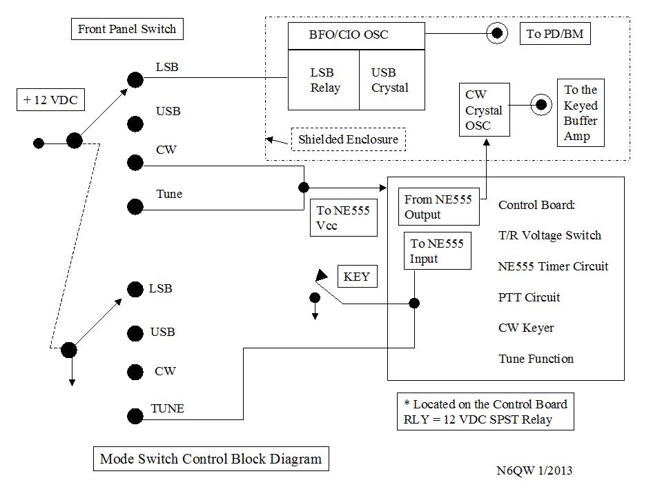
I then developed a control circuit that did several tasks. One task was to provide break-in operation with a second to have functionality for both tuning the rig with output that required no "key down" or regular CW operation. As a bonus this circuit also providing the switching of voltages to go from Receive to Transmit and even included the usual outboard linear amplifier control. From a block diagram standpoint this is what it looked like.
This is a schematic of how it was done.
I spoke of the relay bypass on the IF Mechanical Filter
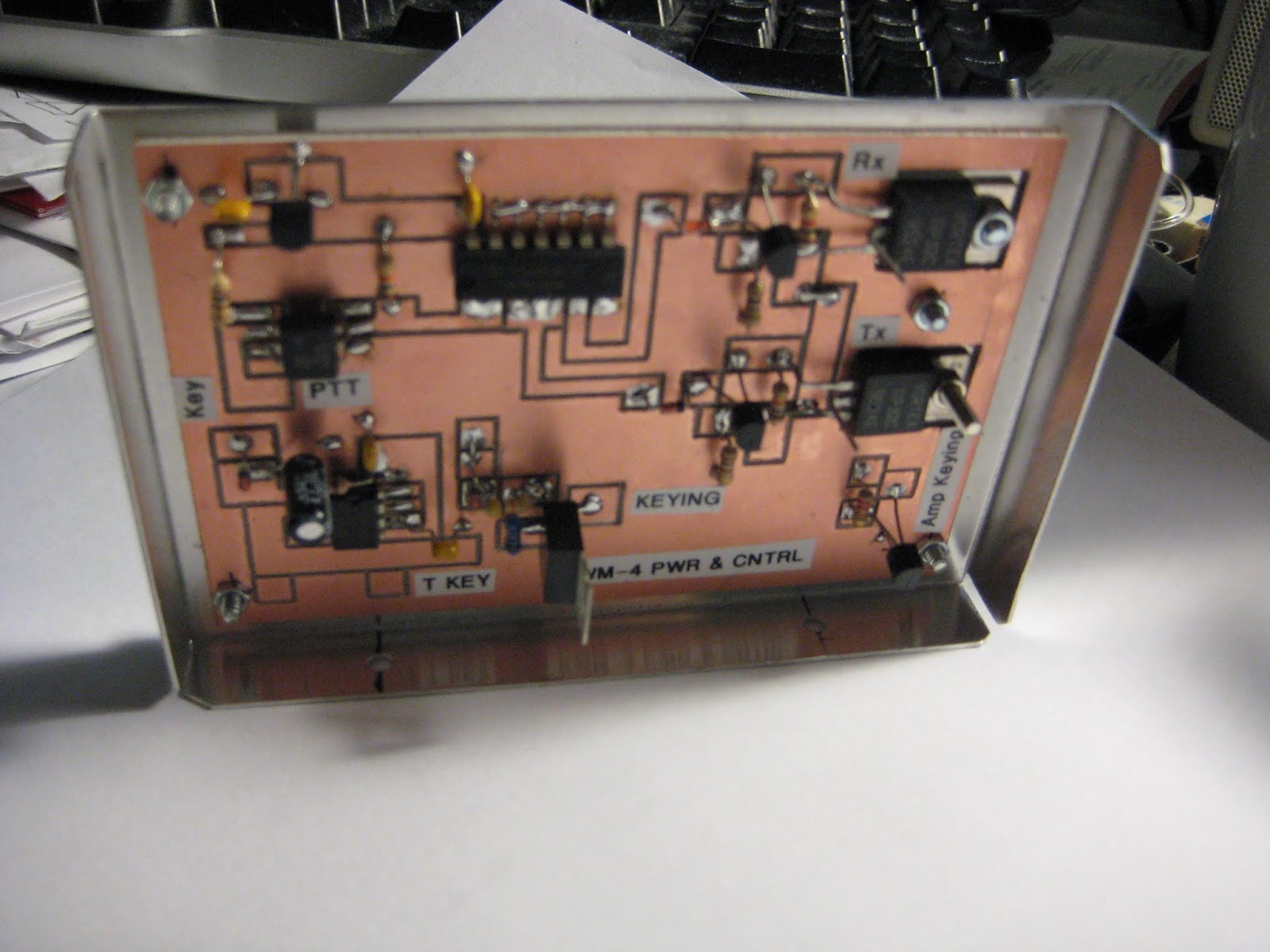
Some Snaps of the Control Board
Yes Virginia, all of the boards were made on my CNC machine. I think it turned out pretty cool. But then again I tend to think all that I do borders on genius.
Now with the advent of the Arduino and the Si5351 a lot of what I did six years ago will be just a few pieces of hardware aside from the Arduino. To wit the 1N914's coming off a the 7400 IC could now connected to pins on the Arduino. The timed voltage off of the NE555 is just a Pin Output to a DC switch that is in an "OFF" state until keyed.
The 4.7 UF was a timing cap. But suppose we use one more pin with a switch that would give you a default time value and engaging the switch selects a different value. Two switches could give you four time values.
I would consider the use of the third clock on the Si5351 that would provide the CW oscillator frequency that would operate in the same way the standalone did in the KWM-4 and that would feed a keyed buffer.
All of my sketches include a TUNE function that generates a pulsed 988 Hz tone that is fed into the Balanced Modulator. That same code can be modified to provide the timed voltage to the buffer as well as the side tone and show on the display you are in the CW mode.
I just may have to build what I suggested and then this could be used with other homebrew SSB transceivers. At this stage it is always best to noddle a bit more but I think I have sketched out a possible roadmap to add the Arduino to the mix. If you used a Mega 2560 (more pins) then it would be possible to add my CW sender software so you could add a keyboard for sending CW --and even call up canned messages. With the Arduino anything maybe possible! (For those still subscribing to QRP Quarterly several years ago, Ben, AI6YR and myself did a series of articles on a CW Sender using the keyboard.)


.jpg)
.webp)
.jpg)


.jpg)