As a homebrewer (starting back in the early 1950's with a CK722 transistor) I find that today we have lost an important insight into what we do. I didn't; but many have.
Gone is the quest to learn new things and to strike out on our own. Frequent emails to me ask where is the circuit board or send me the Gerber Files. That gives rise to several questions.
So why do you need a circuit board and
Why can't you design one yourself?
The same applies to Arduino Sketches and Code. Typically, most rigs are not totally dependent on just one set of software to run the radio. The problem maybe is that to write code, one would really have to know something beyond asking for the circuit board.
I really don't have any special radio skills. But what I do have is some processes to attack problems and processes to approach a new radio project. I call it noodling and there is a lot of research that I do up front. The last thing I do is to turn on the soldering iron. Thank God for simulation programs like LT Spice.
That simple one transistor microphone amplifier (above) was extensively simulated and that effort has borne fruit by the number of excellent audio reports. I didn't start with a circuit board. I started by looking at a basic amplifier circuit and on from there. One soon learns how the value of the emitter bypass cap impacts the circuit performance. Now that exercise is a part of my knowledge base.
There are those who will fester over why the resistors R6 - R8? They are there to simulate a 10K output pot. So, when you build the circuit, you install a 10K pot and no resistors. The output taken from the center wiper to the 0.22Uf cap which connects to the relay terminal.
But as I share the circuit -- the question persists where do I get the circuit board frequently arises? Lew McCoy, Wes Hayward, Jean Sheppard and James Lamb would not even think of circuit boards! Excelsior!
This is what happens when your mind is on circuit boards and not the circuit... you Strike Out!
Yes! The PSSST has "street creds" as it has been recognized by a well-read blog post. To The Tribes (BITX, TIA, EMRFD, Nano VNA and Facebook groups) it is posted there without having a link to one of your Tribes. OMG, somebody went around the Tribal system of group recognition.
But there is a huge problem with our hobby, and that is how we view things and worst of all what we have become.
So far there are two comments on "hackaday" there may be more by now. I suspicion that the two posters belong to The Tribes (BITX, TIA, EMRFD, Nano VNA or Facebook groups) as this is what they posted.
Later Input as there now are over 6 comments and one in particular has me scratching my head. The commenter denigrated the design as using musty old parts and the PC Board with squares was like doing brain surgery with a rusty spoon. But the clincher was that I did not use an accessible design. I don't know what that means and likely he doesn't either!
You can do all the software tricks you want and include ports or WiFi to make software changes but even the IC7300 and FTdx101F have some analog devices in the loop to generate RF, amplify it and send it into the ether. Like on the front end are some DBM's with a post mixer amp that has a high intercept point and considered a strong amplifier.
The Arduino and Si5351 are devices with accessible design features. So, is he a man talking like a man with nothing to say? When you know stuff, you can do stuff. But when you don't know stuff, you can only make stupid comments like accessible design.
One post in essence took to task the project because "it has MORE than 7 transistors" if you count what is inside the Arduino, Si5351 and the LM-380.
Well counter to that, I can respond by saying let's make it 10 transistors as I substitute a J310 FET VFO (at 5 MHZ) for the LO, another 2N2222A as a 9 MHz BFO and use a TIP32 as an audio amp stage. That is 10 transistors! BUT now there would be the criticism that it did not use the latest technology and the audio is weak!
The second post complained that it is painful to have to listen to a radio without AGC.
Well, this poster likely has never used at Bitx20 or for that matter really sat in front of a PSSST and just listened. True it does not have AGC; but so, do a lot of other radios lack this feature. Mind you it can be added; but just adds a lot more hardware to the project.
None of the negative comments reflected on the Steerable approach, nor that it really only uses 7 discrete devices, yet has a superb frequency readout and a very stable LO.
What have we become in that the only comments that can be made are negative! They completely overlook that indeed someone not using The Tribes (BITX, ITA, EMRFD, Nano VNA or Facebook groups) has a working radio employing really innovative concepts?
This begs the question "Have these several posters really ever built anything or is their sole goal to find something trivial that can be "festered' upon within their Tribes? Is their goal to denigrate what I consider "true homebrew". OK you guys, let us see your SSB Transceiver designs?
With only 7 transistors I keep being amazed by the performance of this Jewel! Yes, it is like a Crown Jewel and I regret not using the Steerable IF Module (shown below) in other projects. This will now become a staple of future projects.
[ November 13, 2021. I now think you can do it with SIX (06) transistors. If we steer the Mic Amp with two more relays, we now can also use it as the Audio Pre-Amp as it is exactly the same circuit. Scroll to the end. So OK the challenge --can we do it with just 5 Transistors?]
Here is what makes this unique and it wasn't until I made a block diagram that I realized the impact of the design.
The initial thoughts on this IF Module were that it would be steered between two ADE-1 DBM's depending upon whether it was receiving or transmitting as shown below with the ADE-1's. In Receive, the signal is steered to the input side of the IF Module from the Rx Tx Mixer stage wherein the output side is steered to the (left) ADE-1 which is in the Product Detector mode and on out to the Audio Amp.
Switching over to Transmit the signal from the LEFT ADE-1 is now an DSB signal as that ADE-1 is now in the Balanced Modulator Mode. The output side of the IF Module now a SSB Signal is passed on to the RIGHT ADE-1 where it is mixed with the LO and on to the BPF.
So, what is significant is that the 1st Transistor in the Module is always a Post Mixer Amplifier and the 2nd one a pure RF Amp. The 1st is always seeing the same loading and a clue that the gain levels of the two stages will be different and are. This is where LT Spice enables you to "twiddle" with the parameters and for the whole assembly the gain was optimized. Of concern too was the gain of the stage for receiving and transmitting so that signals being received and transmitted were consistent.
I have extensively documented this project and in hindsight that was a terrible mistake and here is why I should not have done it! Too much documentation perpetuates the loss of creativity.
Many homebrewers and blog readers simply want to have all of the data including schematics, part number lists, Arduino Code, PC Board Layouts, LT Spice Simulations and performance calculation and need I say it URL Links to Source Suppliers. If it were possible, they would want me to build it too. (I have been asked in the past to do that.)
I do appreciate how documentation can help facilitate the
construction of a project. But my fear is that thinking that this would
encourage potential homebrewers to take the leap it in effect discourages
creativity. Building it like Pete may not be the best mousetrap. Certainly, there are
a few who may move beyond that but that is the point they are the few and truth
be known they would probably make that move regardless.
Help is one thing enabling laziness is another. As I said
before give me a schematic and my “fabrication process” kicks in to make the
project a reality. An extensive documentation of a single project is not an
inherent fabrication process to enable taking on other projects. The
documentation of a single project is simply a by-product of the process –not
the process itself.
Let me continue on my soapbox. I think in Modules and that
is key to my fabrication process. Those who only want spoon feeding have missed
the power of the module which is of course chunking a project into manageable
pieces. With this process you can test as you go and downstream when you want to try an
upgrade you deal with just a module and not destroy a whole radio to make one improvement.
From my perspective the
documentation created for the PSSST is spoon feeding how to build it! Removed from that equation is an underlying process with the
modular approach. Regrettably extensive documentation does discourage creativity.
Steerable modules have been used by me for some time which caused me to get hate
mail about the use of relays and why not diodes. Diode steering has been used
by me but my concern is signal isolation. That said the Steerable IF Module
(not just the Filter) is a 1st for me and it works.
There is another pet peeve -- despite the Herculean effort to create and include all details I still get emails --Why do you not connect R8 (50 Ohms) in the hardware but LT Spice shows R8. LT Spice also had a note R8 is a load used in the simulation; but not connected in hardware. I hope that guy gets a short in his coax! Documentation enables Laziness!
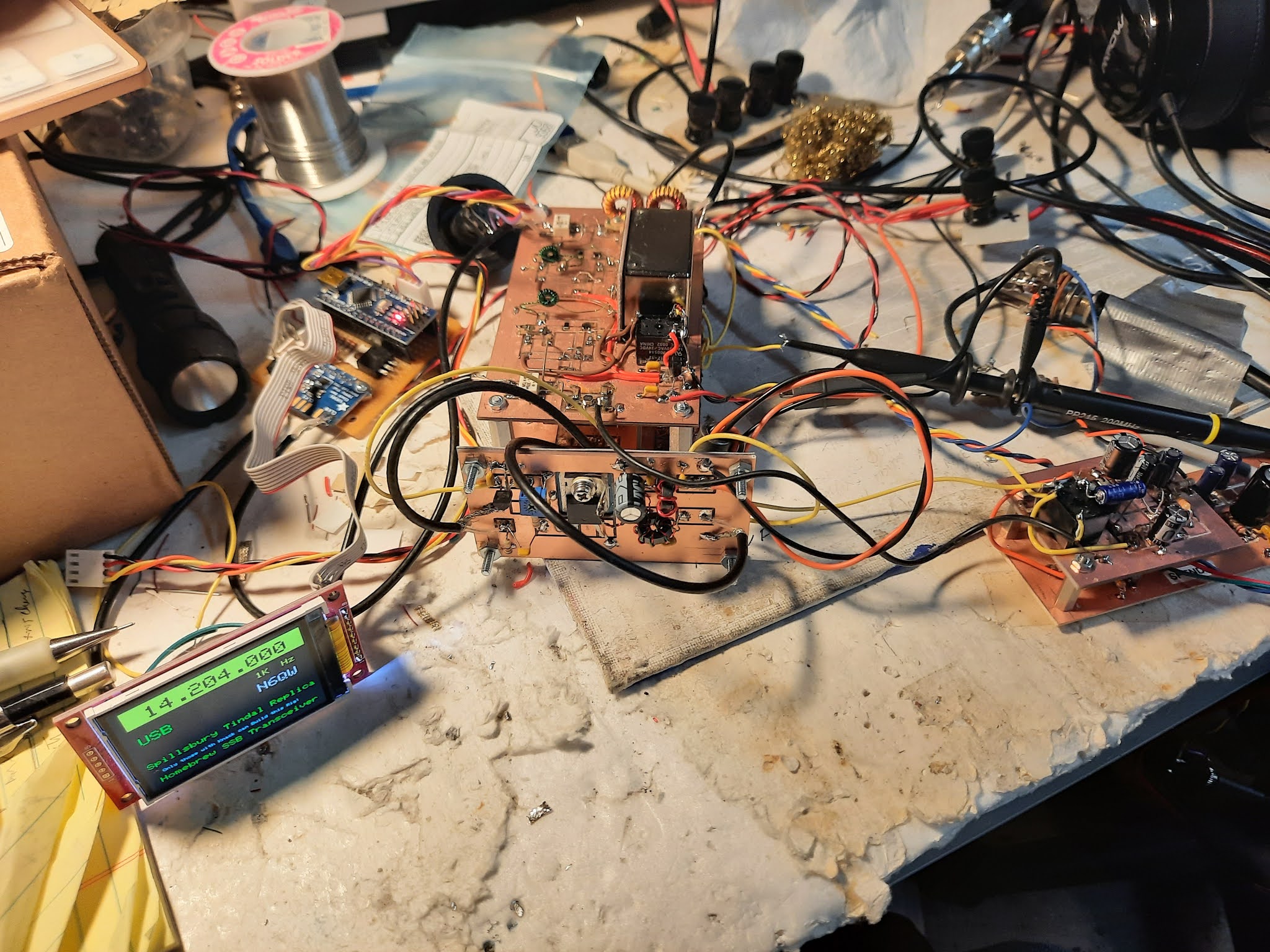
The PSSST ~ You know when we want to get someone's attention we go "PSSST". Well it also is an acronym abbreviation for "Pete's Simple Seven SSB Transceiver!" Did I get your attention?
I have posted videos of how the receiver portion sounds on crowded bands and hopefully you have been impressed. I was!
My work involved NO bilateral circuits, NO TIA amps, it has not been published QEX and there are no Facebook groups and neither are there any group.io lurkers to make snarky comments. The band of choice is 20 Meters
The best part there are only 7 transistors in the whole rig. Five of the transistors are 2N2222A's along with one 2N2219A and one IRF510. The power output is 4 watts and I have a confirmed "1st contact" (DX no less to Canada @ 1200 miles). [I now have a RD006HHF1 in the mix versus the IRF510 and have made a half dozen contacts using the PSSST.]
What sets this rig apart from other topologies is the how it is works. There are two circuit modules that are relay steered to have different signal paths depending on whether in Receive or in Transmit.
The 1st module consists of two 2N2222A's and a 9 MHz Crystal Filter. The input and output are steered between two ADE-1's. On one end the ADE-1 is either the Balanced Modulator or the Product Detector.
In receive the IF Module output is connected to the ADE-1 in the Product Detector Mode. But on Transmit the input of the IF Module is now connected to the same ADE-1 which now is the Balanced Modulator.
A relay on the 1st ADE-1 connects to the Audio Amp on Receive and to the Microphone Amp on Transmit. In case you are counting all this is done with three SPDT communication relays.
Shifting to the 2nd ADE-1 on Receive it is the Receiver Mixer and on Transmit it is the Transmit Mixer. At all times the 2nd ADE-1 is connected to the Band Pass Filter. However, the 2nd ADE-1 is either connected to the input side of the IF Module on Receive, or to the output side of the IF Module on Transmit.
Noteworthy the BFO and LO are always connected to only one ADE-1 and are not switched.
The second "steerable" circuit module is a single 2N2222A that acts as the Receiver RF Amplifier on Receive and as the Transmit Pre-Driver on Transmit.
Stop! Up to this point only FOUR 2N2222A's are used in Receive (Audio Pre-amp, IF Module and the Rx RF Amp) and FOUR 2n2222A's on Transmit (Microphone Amp, IF Module, and TX Pre-Driver). I would call that Minimalist!
The Audio Amp uses a 2N2222A driving an LM380N-8 for more than room filling volume. The Microphone Amp uses a single 2N2222A. A good deal of time was spent optimizing (LT Spice) the Microphone amp to have lots of low frequency gain, so the sound has lots of "presence". This same circuit is the audio pre-amp.
Note to those who don't read the print. What connects the Pre-Amp to the LM-380N-8 is the 10K Pot. Read Carefully that R6-R8 are there only for simulation and are replaced with the 10K Pot. Having R6-R8 gives the three plots to simulate a Pot. I have to say this because undoubtedly I will get two emails that say "I don't understand the schematic". Friend learn how to read!
USE ONLY THE TO-18 VERSION OF THE 2N2222A. Because they are being driven hard -- they run hot!
A lot of effort was spent with circuit simulation and hidden in the blocks are optimized amplifiers and extensive use of circuit matching. I am particularly impressed with the 2N2222A over the 2N3904 for this application as it current limitation is 500 ma (versus 200 ma for the 2n3904) and it can be fitted with a heat sink.
Now there are those who will go to Google and tell me immediately that the 2N3904 total device dissipation is 625 mw versus the 2N2222A at 500 mw. But it is hard to put one of those cool top hat heat sinks on a 2N3904!
Keep in mind NO BITX, NO TIA and NO QEX. This is not a kit but holds the promise of a minimalist rig goal that sounds really good. I am encouraged by the Pout (4 Watts) on 20 M and think with a different filter (like 10.7 MHz from Spectrum Comms. UK) this can be transported fairly easily to 17M.
I need to dig out my digital adapter and run this up on FT-8 and WSPR --just to quantify how good the hearing part is.
The those who never have built anything; but act as if they know everything about anything must be suffering terribly. Aside from a few block diagrams they have nothing to pounce on with the intent to denigrate.
In time I will be publishing (note I said publish) detailed circuit, information, LT Spice simulations, and lots of photographs of the fabricated modules. But for right now I am just delighting at having been successful with the PSSST.
A ham yesterday got an email about his homebrew rig from a lurker. The email contained factual errors and it was obvious the person sending the email lacked technical skills and yet spoke with such authority. Thus, before you send me one of those emails, I have the hardware and the data. You now also have the video of a QSO.
It is like the ham who commented on a you tube video I made on the HW-101. He said if he owned one, he would never do what I did. Well friend if you owned one, you would do what I did. The bottom line -- if you haven't built the PSSST -- you can't possibly know!
Listen to the CQ WW CW Contest. Can your radio hold up in a crowded band with lots of strong signals?
****
Now with a Color TFT display! 11/05/21
First Receive and Transmit tests. Very Promising... HD8R is an Expedition to the Galapagos Islands! 11/04/21
Just as there is a difference between a 29A and a 44DD, the replacement homebrew audio amp for the eBay module certainly points the direction and stands out in a crowd. It is superb sounding with the final device being the the LM-380N-8. This will be in the final design.
The 1st Sounds of the Minimalist SSB Transceiver. I held the phone up to the earbuds to make the recording. C Change - The eBay amplifier module is underwhelming in its performance. I will have to sub in one of my homebrew modules. But this is encouraging! It does have a formal name but not a YL's name.
These days I seem to be reflecting on the past and harken back to 1959 with an analogy. So in 1959 (I was 18) my thoughts about an ideal girlfriend was to think in terms of the minimum requirements for a YL such as could she change the spark plugs and set the timing on a short block Chevy engine. More importantly did she know what needle nose pliers were and did she know how to solder a Western Union splice joint. Yes indeed, those were the minimum requirements.
Short Block Chevy 350 Engine
That is a 57 Chevy -- a Really Hot Car. The Girl looks OK Too ~ Healthy is a good word!
Yes , this is the official Western Union Wire Splice!
These are not torture devices; but real Needle Nose Pliers
[ I have posted the above photos as many modern hams and many Box Top Extra's (BTE's)) who only use Facebook, would not know of what I speak.]
Likely an 18 year old kid today would have a list including: Is she hot looking, does she have money, does she drive something newer than a 2 year old car? Does she have a posse on Social Media and does she live on the better side of town?
In 60+ years the focus has shifted from skills (wrench turning and soldering) to the external environmental features (looks, money, power)
In today's world regrettably, many hams evaluate a homebrew project based on can it be found in EMRFD, does it have TIA amplifiers, does it have roots in a Bitx topology? Is it SDR based with a Teensy and Nextion touch screen display and has it been showcased on 'hackaday", mentioned in a well known podcast, has a Facebook following or is published in QEX?
Failing to meet any of those 2021 environmental criteria, then most of today's hams and certainly BTE's would move on and not take a second look. Bummer! They have just missed an opportunity to experience building and using a workable transceiver that performs well and will never see the pages of Facebook!
Unfortunately, Social Media platforms like Facebook have "trained" the modern ham to think in narrowly defined paths which only run through these environmental aspects. That is so sad!
But suppose, just suppose you could have a design that uses the minimum number of parts with the same device in all sockets and have a working rig, yet it never saw the light of the aforementioned 2021 Environmental Criteria.
This is a tall order; but suddenly there is now a shift back to skills and tribal knowledge! Thusly knowing stuff, you can do stuff.
Stop looking --you can't find skills or tribal knowledge in Facebook! Today's QST won't help either unless you are shopping for a $6K transceiver from offshore!
I am taking on this project adventure to show that you can build a proper SSB Transceiver using some very basic circuit elements. Additionally this is an in your face challenge to those who never build anything; but often speak like experts about everything.
It does have a name; but is being withheld at this time. You will just have to keep tuned to this channel to find out.
In case your wondering --the YL in front of the 57 Chevy was not my girl friend!
A "New Project" and it is not another homebrew solid state SSB Transceiver!
I have been posting information about dBm and Ferrite/Iron Powdered cores with the calculations for turns and inductance. That was no accident that it was posted. Thus you are well ahead if you were able to follow that series.
So we have a couple of facts --it is not solid state, it is not SSB and it is not a transceiver. That sure narrowed the field down (by a lot).
But it is a method of generating RF and it is usable for communication purposes.
Start scouring your junk box, your friend's junk box, eBay, Antique Electronic Supply, radiodaze.com and amazon for a list of parts that will be found on this link. (to be provided).
We will endeavor to provide a insight into this homebrew project that goes well beyond whipping out your H4 and measuring SWR. I hope to cover some theory on why it works (lightly of course) and to share TKT's not previously exposed. [Ok you forgot, a TKT is a Tribal Knowledge Tip. ]
BTW you will also need some hand tools including a miter box and miter saw, an electric drill, some files, a Phillips and flat head screwdriver and some decent pliers, tin snips, and a square. A vise sure would be handy too.
This project may actually give some ARRL Extra's a chance to learn some stuff so they can do some stuff.
Pete N6QW
At small family gathering over the 4th of July, my kids suggested playing an old family game. The gist of the game is that you are given a situation and then asked to respond. What would you suggest for the scenario I was given. There are no right or wrong answers!
The scene: You wash up on a remote pacific island and on that island is Rudy Giuliani, Marjorie Taylor Greene, Pope Francis, Lorraine Bobbitt and Tiny Tim. I had a creative and clever answer.
2nd Series of Tests of the MC1496 DSB Generator 7/11/2021
The Carrier Input Level is on the Critical Path and Affects Carrier Suppression!
Pete N6QW
Some Pasta Pete photos from the 4th of July Cookout! This was Dinner for 4.5 (Four Adults plus my 8 month old Granddaughter. She had some of the grilled Salmon and enjoyed it using her new two front teeth!)
A link to a Compendium of Information on DSB Transmitters fromN2CQR
So Ok you lack skills and lack experience in building stuff ! Thusly, here is your chance to overcome those shortcomings by building a simple VOICE transceiver only it is double sideband. Think of it as an AM Signal with no carrier.
Double Sideband (DSB) is an authorized form of amateur transmission and so rebuff any claims from the FLEX guys that you can't use that radio here -- to the contrary -- it can be used any place where phone operation is authorized! They are just plain jealous that they had to spend $6K to put out a signal and you had to spend a small fraction of that sum.
The beauty of such a rig is that there are few components and such a DSB transceiver builds upon the N6QW Direct Conversion Receiver found in SPRAT 187. You already have the most critical part and that is the LO which makes it rock steady and avoids the criticism that you are drifting. Here is the link to the project N6QW DCR/DSB
The DSB Transmitter topology is in work and will be under test here in the real near term -- like maybe today. Today is Here!
The heart of the DSB Generator is an MC1496, available from Amazon in leaded form and Mouser in SMD with total unit cost at either source for less than $1.
The other piece the microphone amplifier is a 2N3904. I have built my DSB generator on a piece of single sided copper vector board and the size is 2" X 2". Following that will be a BPF and a couple of amplifier stages and a W3NQN LPF.
For good measure and for the anal retentive nerds who worry about such things, we could follow the mic amp with an 3 kHz wide audio filter such as those used by KK7B in the R2 and T2. At this stage I do not believe it is necessary. I am just trying to head off the emails from those who never have built stuff and see this as a Gotcha!
For those about to email me about using the NE602 --don't waste the keystrokes. You want an NE602 then have at it. Look at the cost -- NE602's costs a lot more than $1 and there is virtually no performance advantage. This transceiver will have two MC1496's with one in the Rx and the other in a Tx.
Now we must be good hams and think and act responsibly about the following.
You are putting out two sidebands --so refrain from connecting this to a KW amp -- a 1KW USB signal on 40M might not be appreciated. So keep it QRP at 5 watts with an IRF510 for the final. You will make many contacts!
The power spectrum issue drives a second consideration of a watering hole frequency. Already there is a 40M QRP SSB frequency and that is 7.285 Mhz. So if we operated on DSB on 7.285 --there will be less CRAP [CRAP = Constant Ragging And Poking] from the FLEX Radio Police.
Finally keep in mind out of band operation: while one Sideband may be In Band the other may not be in the event you are working very close to the band edges.
About 6 months ago I made my 1st ever 12 Meter Contact using 5 watts. So the higher frequency bands are like a lady in heat! I would avoid 20 Meters; but certainly 17 Meters would be ripe for the pickings at 18.130 MHz. In case so inclined 20M SSB QRP is 14.285 MHz.
In due course I will provide some schematics --but you could do a bit of research by visiting Google and You Tube. Peter Parker, VK3YE has quite a few DSB you-tube videos and is an excellent resource.
Stay tuned for more opportunities to harass the FLEX Radio 40M Radio Police.
73's
Pete N6QW
If you are not a member of the GQRP Club, then you are wrong!
[See the Latest Video Embed 7/8/2021]
This is the front cover of SPRAT 187, a Publication of the GQRP Club. Having a project on the front cover of SPRAT is significant and is akin in the ham radio world to having your face, band, or boobs on the cover of Rolling Stone Magazine. Shamelessly it is my project and so I am on the cover!
The article covers a Direct Conversion Receiver (DCR) that by the estimation and comment from many who have built the DCR is "Jaw Dropping" in terms of simplicity and outstanding performance. The basic innards are but one IC the MC1496, Double Balanced Mixer. The other "HUGE Bonus" no drifty analog LO. If you have not taken the leap to the digital VFO using the Arduino and Si5351, this is your opportunity!
A "Stop Order" to those of you that have never built anything, who are about to pen me an email telling me why the NE602 is so much better. I don't care to receive your email and this is not about comparing Double Balanced Mixers.
It is however, an application of the MC1496 that has been around so long it qualifies for membership in the AARP. Check out commercial ham equipment built in the 1970's/80's and typically you will see an MC1496 in the design with often several being used. If you check what I call the Ham Radio Bible (Not EMRFD), Solid State Design for the Radio Amateur, many of the projects are built around this device. Check out pp 203-205.
The MC1496 can be purchased in the SMD configuration from Mouser and in the leaded configuration from Amazon. In both sources, the unit cost is less than $1.
[A word of caution -- the myriad of older MC1496 designs use the 10 Pin metal TO-5 sized device. The current configurations (SMD or leaded) use the 14 Pin DIP. There is not a total pin for pin compatibility --so if you are using a schematic for a project that was built around the TO-5 but you wired it with the 14 Pin DIP -- that means I will get the usual email "your design sucks" -- no it doesn't suck; but it is that you failed to heed this caution.]
So you are not a member of the GQRP Club (that is too bad); but you can follow the project here Of note is that within that link is a further link to two hams in the UK who have built this DCR and they have much added technical information and alternative construction methods including Gerber Files so you can make boards at home.
Now being a radio genius I have it arranged that you must contact me to get the Arduino code. This affords me several pieces of data. I get a rough number of hams looking to build the project and it also gives me market penetration and segmentation data.
So OK there have been over 60 requests for the code so far with half of those coming from the UK which tracks that the bulk of members are in the UK. I have also found out that several were built without contacting me for the code. So that is another plus for the project -- any old code will work. But the input from one of these builders was "jaw dropping" which adds to the other jaw dropping comments.
When you visit the link there are several embedded you tube videos where you too can experience "jaw dropping".
Just so you fully appreciate the Left Coast life style, I received this advert in the mail last week. Note: Woodland Hills (the Drive Thru Location) is but a short jaunt from my QTH and an alternative "Hollywood" enclave. The Motion Picture's Retirement Home is also located here!
(Am still wondering why I was in the targeted ad mail group. Firstly, I don't smoke and secondly I don't use POT!)
Rock On! Do Not Let World Events harsh your mellow!
Well it is isn't different from many other rigs I have built. The Tried and True Plessey Amp stage is installed on either side of a packaged crystal filter and life moves on with a standard bi-lateral IF module. This time the amps are fabricated using SMD 1206 sized components and the FT-23-43 cores.
The 2N2219 is used in the Bi-Directional Amp stage as well as the Driver Stage. The Final is an IRF510. The Mic Amp is a 2N3904 and the Audio Amp a 2N3904 with a LM-380N-8.
The Nano/S-5351 provides the LO and BFO and this one has the larger ILI9341 Display. The physical size is 6X8X2.75 inches.
I made an error when I cut the 1st front panel but with a bit of aluminum expanded metal to cover the hole it is now the back panel. It looks like I was trying to pay attention to provide ventilation -- Nope --just repurposing some material.
I am looking to build a N6QW version of the Spillsbury Tindall SBX-11A
Some very clever ham suggested this be called the "Spillsbury Do Boy". Hey that has a nice ring to it.
Still a lot of work to do but is getting close to being done for Field Day. The best DX so far is Brazil running 100 watts.