4/27/2019
The Future of our Hobby is Here! Forget those simple rigs with homebrew crystal filters, cranky IRF510's and the analog VFO's. SDR is the wave that is building strength just like a Tsunami.
With the Soft Rock V6.3 SMD Version + RRPi2
With the Omnia SDR and RPi2
Pete N6QW
How Simple & How Cheap can you build a Homebrew SSB Transceiver?
4/26/2019 --- I just converted my websites from an obsolete Windows Based Server with GoDaddy to their cPanel (Linux). This was a cost issue as a one year renewal of the Windows Server would buy three years on the cPanel. GoDaddy is discouraging the use of what they call the Obsolete Windows System. So I had to migrate and reload the whole pastapete.com, jessystems.com and the n6qw.com sites to the Linux based servers. Some files and links got lost in the translation --so you might not be able to see everything!
Essentially I have to open every link to verify that it works --that may take some time. Saving a few hundred dollars sure brings a lot of grief!!!!!!

4/25/2019 ~ A Case for NOT building Simple SSB Transceivers!
Over the past several years I have presented designs for somewhat simple SSB transceivers many which can be built using very few devices. One side of this equation is good, for it is a challenge to make a working transceiver using very few and in most cases common readily available parts.
The other side of the equation however shows that simple designs using clever circuits is just that … a compromise. Given our current band conditions and according to the sunspot cycle oracle, she is telling us that the next cycle will be in the 100 range which is a) no better than our current cycle and b) about a third of the numbers of sunspots in Cycle 19 which peaked near 300. Simple logic -- our rigs have to be better to be able to cope with the lousy band conditions. Given the simple nature of many of my designs that could spell conflict with the poor sunspot cycle conditions.
The gain distribution often with so few devices (like maybe a dozen total) causes one to put all the gain in the front end where the noise gets the same amplification as the signal. The simple designs lack things like AGC and RF gain control. Internally generated noise is another hallmark of simpler designs. True the Arduino and Si5351 is a huge crowbar but these features address frequency stability not necessarily an across the board "high quality" design.
Next we have the two ton elephant in the room … QRP. Guys and Gals, QRP and poor band conditions are like mixing oil and water. Can you make contacts --sure. But will you make a lot of contacts? Probably not. The die hard QRP guys will tell you it is all about skill and patience. Trust me it is all about high gain antennas and lots of watts. I lived through cycle 19 and with my Heathkit Tener I worked the west coast from my car --all the way from Pennsylvania. I was lucky to get two watts out of that 6CX8 tube. But that was Cycle 19 and the year was 1959 not 2019!
Virtually all of my current designs are QRP -- a couple of tube rigs I built ran 25 to 50 watts. I am able to run 600 watts with most of my current homebrew rigs and often that power level makes a big difference with our lousy band conditions.
Consider that many new low cost rigs are SDR so you have lots of built in signal processing, noise blanking and variable bandwidth filters. That is in addition to rock solid frequency stability and very colorful touch screen displays. It is hard to replicate that functionality in a simple rig with a homebrew crystal filter.
The Sky SDR looks very appealing and while the price seems a bit stiff it does not require an external computer and will give you the tools needed for the lousy band conditions. Get one of the LDMOS amps to go along with this jewel and you have a competition grade station. No longer will you hear "I can't hear you --you are at the noise level". Move up and move out.

The Sky SDR looks very appealing and while the price seems a bit stiff it does not require an external computer and will give you the tools needed for the lousy band conditions. Get one of the LDMOS amps to go along with this jewel and you have a competition grade station. No longer will you hear "I can't hear you --you are at the noise level". Move up and move out.

I think I am convincing myself to quit focusing on simple designs so that the rigs could be built by many prospective homebrewers. My next builds will shift the focus from simple based to performance based. I will get arguments from some of you --BUT these are two different worlds.
Thus you might not see much new on the blog as I pursue building "the better mousetrap".
73's
Pete N6QW
4/23/1019 ~ Just Announced FT-4 from K1JT!
This SoCal Simple Transceiver with the N6QW Digital Adapter is fully capable of doing FT-8 and without seeing anything other than the pre-release of Info from ARRL should be able to do the new FT-4 mode for contesters. That said given the 90 Hz bandwidth of the new mode, using a commercial filter at 9 MHz would probably be a must. Two such 9 MHz filters are available, one being from the GQRP Club (Z in/out = 500 Ohms) and the other Model 351 from INRAD (Z in/out = 200 Ohms). The match for the latter is a 4:1.
73's
Pete N6QW
4/20/2019 This is why you Must Build the SoCal Special!!!!!! Tnx to N4CCB.
Here, I thought all it took was wearing a European Beret in the Super Market...
Pete N6QW
Sketch for the SoCal Simple SSB


Above are some photos of the display screens on the 1/2 OLED. You will note FT8 is already "dialed in" on VFO B. When you switch between VFO A and VFO B, the screen displays which one is ON and which one is OFF. On initiating the TUNE function the word TUNE appears between N6QW and 100 But actually in TUNE the only thing displayed on the screen is the word TUNE and VFO A frequency. In my own code I can automatically send my call sign in CW after the TUNE code. If you would like this code send me an email to n6qwham@gmail.com.
If you simply install a full OLED versus the 1/2 OLED --you will get a display; but it will only cover 1/2 the screen. To utilize all of the screen space on a full sized OLED entails major programming changes as to the display character text size and the physical locations of information. I do not plan to offer the coding for that. This is the time YOU learned how to do it!!!
CAUTION: Depending on who makes the OLED there may be differences in the connection pins. On some full size OLED's the connections are +5, GND, SDA, SCL while others are GND, +5, SDA and SCL. You typically only smoke one OLED costing $8 and then you exercise care in how you connect things!
BTW for reference purposes the 1/2 OLED is resting on my trusty Pentel Mechanical Pencil.
There is a plan to make a you tube video of the Arduino/Si5351 + OLED so you can see first hand how it is done. But that won't happen for several days.
Pete N6QW
4/12/2019 We have now Named this New Rig: The SoCal Special!


This Amp Runs HOT! So use a 2N2222, TO-18 Style, with a Heat Sink. Do Not Part Substitute. Replace the 2N3904's on the Block Diagram with the 2N2222.


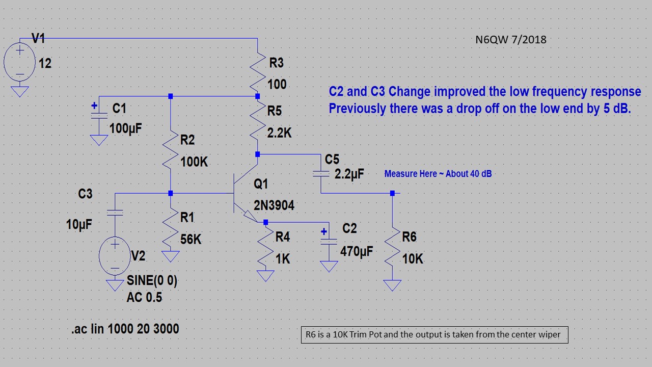
The following is the one transistor Microphone amplifier used with the SoCal Special. R6 is a Trim Pot with the output taken off of the center wiper. As was done in another transceiver I use a relay to switch the input/output of the SBL-1 to either the Microphone amp or Audio amp. Notice the similarity to the audio pre-amp stage in the Audio amp circuit.
The Driver stage currently under evaluation for the project is as follows: [About 20 dB Gain at 14 MHz.] The 50 Ohm resistor R8, is for simulation purposes and not in the actual build


Following the practice suggested by KB1GMX, Allison, I cut-off the IRF510 Drain Pin and make contact to the Drain through the Tab connection. This is the same circuit used in the Sudden transceiver project.


Lets Answer those Questions:
What is the power output level? 5 Watts
Will it use any relays? Yes they cost 60 Cents a Piece!
Will the design use a homebrew filter? Three Options including one commercial and two homebrew [9 MHz commercial, 4.9152 MHz and 12.096 MHz homebrew.]
What band or bands? Most likely 20 Meters!
What is the method of frequency control? Nano/Si5351
What is the size (leaded or surface mount drives this)? The answer is Leaded Parts so moderate size but in a unique box.
Will it be sideband selectable? Yes & Dual VFO's
Will it have CW capabilities? NO!
What is the method of frequency readout? 1/2 OLED
Will it do FT8? YES!
Will it use a circuit board or ugly construction? Both
What is the price point? $100
After a recent experience at examining the schematics of a commercial product from Heathkit (HW-18), I concluded that to answer this question invoves a lot of thinking out of the box? This must have been the process used by the Heathkit engineers or very likely that they were told to design a product that works and would cost no more than $60 yet could be sold for $120. I suspect it was the cost driven design that was used.
But to really answer that one question (and yes I am about to create such a project) involves asking many more questions.
- What is the power output level?
- Will it use any relays?
- Will the design use a homebrew filter?
- What band or bands?
- What is the method of frequency control?
- What is the size (leaded or surface mount drives this)?
- Will it be sideband selectable?
- Will it have CW capabilities?
- What is the method of frequency readout?
- Will it do FT8?
- Will it use a circuit board or ugly constrution?
- What is the price point?
Wow you have to ask a lot of questions just to answer one question. Undoubtedly a simple answer to the 1st question is to simply purchase the Bitx40 semi-kit and that you can have in your hands for about $60. Done, finished and on the air in about 1/2 day from opening the box. Or for about 2X that cost you can have a multiband uBitx. So why even read on?
But if you want to delve deeper into actually homebrewing a rig totally from scratch then there is another approach and that is to DIY. I have scratch built a Bitx20 over 10 years ago and more recently a Bitx40. Undoubtedly it is an excellent design and low cost but what if you wanted to do it entirely on your own how would you do it?
There are some other considerations for a DIY and that includes having some basic understanding of electronics, having decent test gear and having some software tools like LT Spice and Elsie. But this is a learning experience and a journey of more than 1/2 day.
BUT before you light off the soldering iron, turn it off and spend lots of time noodling over the rig elements, the method of fabrication and the complexity such as one band or multiple bands.
There is another factor to consider and that is what I call using common parts readily available today. I have a junk box full of parts that are totally obsolete and while I can use them in projects you won't be able to find them in the market place. So the challenge is to employ devices like the 2N3904, 2N3906, 2N2219, LM386, IRF510 and SA612. These can be found on ebay and from various commercial resources. Buying these in bulk readily lowers the unit price to pennies in some cases
The 1st major consideration is the method of generating the LO and BFO as this determines the level of the science project you will undertake. A full digital LO/BFO with display can be had for about $20 and does open the possibilities for future refinements. An analog VFO and a crystal BFO very likely will cost a comparable amount. But the problem of stabilizing the analog VFO requires a bit more time.
[Note: 4/7/2019. Just checked Amazon and a two piece buy of the 1/2 size OLED is $9, and a three piece buy of the Nano V3 is $13 and the Si5351 can be found with connectors installed for $4.50. Add an encoder from Bourns( Digi-Key) at $1.38 and the cost really, with a chunk of perf-board and some switches --less than $20. Code abounds so what are you waiting for?]
[Note: 4/7/2019. Just checked Amazon and a two piece buy of the 1/2 size OLED is $9, and a three piece buy of the Nano V3 is $13 and the Si5351 can be found with connectors installed for $4.50. Add an encoder from Bourns( Digi-Key) at $1.38 and the cost really, with a chunk of perf-board and some switches --less than $20. Code abounds so what are you waiting for?]
A third option is a VXO which somewhat limits the frequency excursion and finding crystals in the right ranges to match the filter frequency is somewhat more complex but not impossible. In several rigs I built I used a fixed frequency range in the VXO part and mixed that with other crystals to form a synthesizer so that a greater frequency range within a band can be covered. For a 20M radio with a 4.9152 MHz IF I used a 12.288 MHz Super VXO mixed with several 6 MHz range crystals so that the output was near 19 MHz, and when down mixed with the IF BOOM gives 20 Meters. Two 6 MHz range crystals enabled about 120 kHz of coverage. The bonus was that the VXO was tuned with a varactor and a very small pot. In the schematic below the SA612 (NE602) is both the oscillator and mixer stage. This all fit on a very small board. Try building a stable 19 MHz analog VFO and this VXO was built entirely "al fresco". Yes this was done 8 years ago.

I actually still have this board as it was removed from the 20M rig and was replaced with the Nano, Si5351 and a 1/2 size OLED. [See the photo at the masthead.] The cost for the VXO would be about $15 but for $5 more you get the display and the BFO. So you can see where I made the cost decision. But the VXO is still an option for you. I would not attempt to build a 19 MHz Analog VFO!
Stay Tuned for more on this project. next I will cover a block diagram.
73's
Pete N6QW


