What a difference one letter doth make ~ A new SSB Transceiver

One Letter Change Makes for a Whole New Meaning.

7-30-2019. Some more rig photos added. I recently said I have built about three dozen homebrew SSB Transceivers --this is just a sampling. That number might be low if you count all the way back to 1970! If any ham has built more than this number of homebrew rigs --let me know. n6qwradiogenius@gmail.com

8-1-2019 This compilation is missing three rig photos including the Belthorn III and the Breadboard SSB. Also missing is the original ZL2CTM SDR XCVR. I think we are beyond 36.


In the background I am working on a new SSB Transceiver that will use the really "old technology" -- a crystal filter. Don't get too excited just yet, as the project is a way off. 

But noteworthy it appears my SDR adventures have left many uninterested in moving to the new state of the art -- that is OK too. Too bad though as it really is the new wave. Our hobby has a very large tent to accommodate the many interests. 


Yes I did work CW at one time...

Belthorn #1, SSB Transceiver from G4GXO
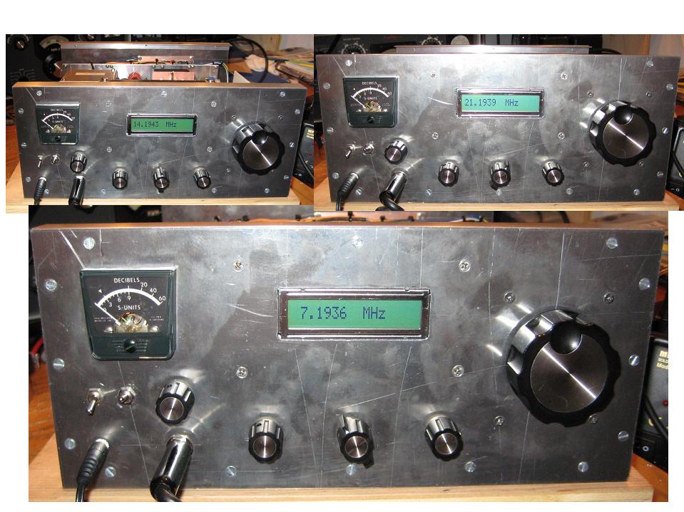
K1BQT's SSB Transceiver moved to 20 Meters. That front panel is 4X 4 Inches and the length is 8 inches. 5 Watts PEP.


W7ZOI's 20 Meter QRP SSB/CW Transceiver
W1VT's, 7 MHz CW Transceiver from QRP Power Article


A 17M Crystal Switched VXO Rig


A Ten Tec Model 540 converted to the Model 544 --my design and my implementation. 


Two shirt pocket Sized Transceivers -- Yes two of them.


The LBS on a Bread Board 3' X 3'


A 60M Five Channel with Tunable Channel #3


LBS II -- A Surface Mount Version of the LBS


 A 20M MMIC Based Bilateral SSB Transceiver 

K1SWL's White Mountain SSB Transceiver


Version #1 of W7ZOI's 20M QRP SSB/CW XCVR.

A 20M CW Transceiver ~ The Wooden Box Radio!

The Bitx20 Built over 10 years ago --with VFO Stabilizer and LCD Display. Sort of advanced for its time!

The Bitx40 before the Raduino was offered as standard.

Ten Tec #150A put on the Ham Bands


Rig in a Champagne Bottle


In many of my past projects I have given them specific names as that is an easy way for me to remember them. We had the LBS (Let's Build Something) which appeared in QRP Quarterly as did the JABOM ( Just A Bunch Of Modules). Then in the GQRP SPRAT we had my Sudden Transceiver. Perhaps many blog readers might remember the Simpleceiver.

Just recently in SPRAT was a project from EA land called the Perigrino which translated from the Spanish means Pilgrim. If you are not a GQRP Club member --you are wrong! Get a membership today!

So as I ponder the architecture of the new filter rig I was searching my brain regarding a special name.  My thoughts drifted to my Italian roots where a term is often used  to describe a countryman, pal or even the equivalent of homie. This would be a perfect metaphor which I see this new SSB transceiver being just that-- a pal. That word is  Paesano. 

Now if you spelled the word Paesano as Paisano -- boom you have shifted the meaning from pal or homie to "country bumpkin". Another such word is Pollock which is a nice white fish but changing the "o" to an "i" you have the word Pillock, which of course means a person who is not too bright!

Now here is a real connect the dots --- a Paisano is a Pillock by another name. I will let you extend the meaning of this to encompass the current world affairs.

This now causes me to ponder how many other words might exist that by changing one letter creates a whole different meaning.

So our new project will be called the Paesano and will be a classic filter rig using some rather basic modules but with a new twist on how they are connected. It should be much easier to comprehend for those of you who could not follow the SDR RADIG. But you do have to know which end of the soldering iron is the hot end.


Thus the Paesano is in work and not even close to sharing anything. However, this could result in a commercial endeavor so maybe not too much sharing. Hint -- it will use an INRAD Model #351, Four Pole Crystal Filter.

73's
Pete N6QW

RADIG ~ Ham Radio's new Tsunami Wave Issue 10

Some New Data ~ Data Points


Here is some setup and reference data for the RADIG. Today I looked at both the design of the J310 Amp stage and the drive levels from the Si570 on all bands. 

Starting first with the drive levels. I put a scope on the output from the pot as it connects to the LO Port on the  ADE-1 and the results are a bit surprising. Keep in mind that the actual frequency being generated is 4X the operating frequency. So at 10 Meters the RF from the Si570 is around 120 MHz. 


  • 160M ~ 544 MV PTP
  • 80M ~ 544 MV PTP
  • 60M ~ 544 MV PTP
  • 40M ~ 544 MV PTP
  • 30M ~ 544 MV PTP
  • 20M ~ 544 MV PTP
  • 17M ~ 512 MV PTP
  • 15M ~ 472 MV PTP
  • 12M ~ 377 MV PTP
  • 10M ~ 320 MV PTP
The outputs below 15 Meters were nice square waves and the surprise was that the lack of sensitivity would most likely only occur on 12 and 10 Meters. Thus my observation of lack of sensitivity previously on 20 Meters was more likely driven by the J310 Amp stage and not the LO drive level.

[This is where the EMRFD illuminati  are supposed to jump in a decry the results. Actually you must look a little more closely at the 12 and 10 Meter numbers as there may be other factors that are skewing the data. There are variants of the 74AC74 that are good to 300 MHz; but this old plain garden variety is only good to 95 MHz which of course is a bit below the 4X for 12 and 10 Meters. So I think what I am saying is that the Si570 is not the bad apple in the barrel. But the lesser drive (resulting from the 74AC74) would impact 12 and 10 Meter sensitivity.]

Back to the J310 stage. Sure enough when I went back and looked at the simulation-- there was about 3 to 4 dB less gain at 14 MHz than 7 MHz. I will now look at a redesign of the J310 amp stage. It may involve just three components. Once I get it potted I will share it on the blog. 

More contacts with the RADIG including a 40M coast to coast with the RADIG and 600 watt amp last night. I got a very nice report. [ At 1630 left coast time today I worked the same east coast station -- that is early for the path. But once again a great signal report. The RADIG Rocks!]

73's
Pete N6QW


RADIG ~ Ham Radios new Tsunami! Issue 2

Loading the RPi3 with QUISK

I have been working on three webpages that detail how to setup the Raspberry Pi3B (also the ASUS Tinker Board) for operation with QUISK and you can see that by visiting my new website. See http://n6qwradiogenius.us

Of particular interest to the RADIG project is how to load the RPi3 and QUISK found at the first link below


This is a bit tedious but covers setting up the NOOBS on the RPi3B and then how to setup the QUISK Software. But the real meat is how to do the actual setup of the parameters within QUISK so it plays with your RADIG which is the second link of the three links. 

For that piece, I will make a video so you can see step by step how to enter data on your configuration. If I were to simply describe it in words -- you would get lost (very likely I would get lost). But the video should help. Give me a couple of days --I want to script it rather than wing it!

Also keep in mind the amazing file that automatically gets placed in the File Manager and should you "goober" things up then it is a simple removal of that file and you can start afresh with loading a new configuration without having to reload NOOBS or QUISK. 

The Third Link -- RPi3 and Ensemble


There is also a third link on the webpage which covers how to mate the Raspberry PI3 with the SoftRock Ensemble. SDR from Five Dash (Tony Parks, KB9IYG). Now this particular Link will serve several purposes and it is not an either / or situation as perhaps was suggested by a comment from the last posting.

The link is useful for the following reasons:

  • The installation is the same whether you use an Ensemble (a single board) or in its place substitute the USB Synthesizer, the RADIG Board, the Driver stage and the IRF510 Final Amp. All else and the interconnects remain the same. 
  • I sense that many hams would like to make the leap to SDR but perhaps feel they lack the experience to build the RADIG Board, and the other associated boards. The Ensemble is a very viable alternative. Thus it provides a path to enjoy SDR at a nominal cost with a known board.
  • I happen to have an Ensemble and thought this would be a good test --if my approach works with the Ensemble will it work with the RADIG? [YES it does!]
  • I keep getting pestered about more schematics and more data. Frankly that is a bottomless pit and would never fulfill those who made the requests. So the Ensemble is an alternative for them, as it is a commercial product and the sorts of detail that is being requested abounds. My SDR adventure is just something I am sharing with you via the blog and website. If you cannot build the RADIG with what has been supplied so far then you best buy an Ensemble. Oh the Bonus with the Ensemble --it has Tayloe Detectors and therefore the subject of why use the ADE-1's now becomes a moot point.
  • Bottom line as always -- usually there are  good reasons why I do things and most of the time the information is very useful. So the real answer to the comment is --BOTH!


I have been doing some experimenting with the hybrid coupling transformer ahead of the ADE-1's. Charlie, ZL2CTM has a wonderful video on you tube of his SDR phasing rig and he highlights the transformer he is using that came from EMRFD. Now immediately some of you who like to pick away at this blog will nod and say EMRFD -- it has to be perfect. That transformer is a 10 Turn Bifilar wound coil on a FT-37-43 core. The common connection goes to the Band Pass Filter Node and the other windings go to the RF Ports on the ADE-1's. Bridged across the total bifilar winding is a 100 Ohm resistor. 

Two components --pretty simple. BUT I found there is a sideband reversal on Transmit in my installation. Mind you we are not disparaging EMRFD nor those who at night, sleep with that publication next to them. It is merely something that causes a reversal so that on my RADIG while you are receiving LSB --it is transmitting USB. Aha --just reverse the leads going to the ADE-1 from the new transformer. I will let the experts who read this blog think that through...

Keep in mind with two other transformers I have used, both do not see this sideband reversal --everything else aside from just the transformer is kept as is. So this has to be something unique with these two components.  

Something is shifting by 90 degrees when going to transmit. I keep thinking about an LO placed above an incoming signal and when the mixing process takes place there is sideband inversion. The current problem must be rooted in a similar process ( I didn't say that was the exact case but just thinking what has been experienced in using total hardware.)

Arguably if you used only this transformer initially and had no other configurations you could say you "goober'd" the wiring in the sound card. But I was careful to keep the very same sequence of connections on the Ring, Tip and Sleeve on the 3.5 MM stereo connectors. The sound card now installed is the Creative Labs Xfinity and the speaker out (Line Out) has colored coded (red & white) connectors which mate with the color coded cable I used. So I am fairly assured that the connections are correct. The fact that it worked properly with other transformers brings to light "something else". A sound card issue has not been totally discounted but everything sure points that way!

So now I would suggest you visit wb5rvz.org Robby has done an amazing job of documenting the builds of the SoftRock transceivers. Once you are on that link click on the current transceiver the Ensemble RxTx . Scroll down to the schematics and Note the Connectors JPI and JP2. These are the Line In and Line Out. Note that even using those TAYLOE detectors, the I and Q are being reversed on one of the connectors. If you have an Ensemble you can see there are pads on the board to do this. So from the git go this functionality has been purpose installed on the Ensemble.

Armed with that information I made a change on my RADIG to reverse the I and Q coming from the Line Out stereo connector to my DPDT relay. With that change it now is receiving LSB and transmitting LSB with no reversal and ditto for USB. One final test is the "look see" on the KPH SDR, which I did and all appears "squared away"!

This story will continue. But two components sure can cause some head scratching. Stay tuned for more misdaventures.

73's
Pete N6QW

Neutralization.

The word neutralization has many interesting meanings. For Mafia Dons, like the Tony Soprano types, the word has the definition of simply el...