July 31, 2024. DEI and being out of step with the world.

That is indeed a serious problem being an OT and thinking (what else) that DEI meant Deliberative Engineering Inquiry. WE are not going to talk about the other currently popular meaning of DEI, but today's post is a trouble shooting problem.


A good friend and fellow podcast participant Dean, KK4DAS has a mysterious occurrence with one of his homebrew rigs. It is not a simple problem like R27 is the wrong value or it's a defective 2N3904, but one where you can see the problem, but the source and cure is hiding in the bushes.

So, how do you attack the problem? The old adage about time is healing applies here too. Step one is to back away from the problem for a short while and resist the immediacy of try this and try that where that only results in raising the frustration level.

A tool, I use, is to write things down on a piece of paper using a two-column approach. One column is marked Known and the other Unknown. My friend has some critical pieces of information in hand. The 1st is that the condition occurring in transmit depends on power level, meaning not so evident at 10 watts but really evident at 20 watts. This goes in the Known column.

In the Unknown may be a case of the Negroponte Switch Theorem (that which was sent by air is now sent by wire and that sent by wire is sent by air ~ Cable TV and Cell Phones). The Unknown is whether RF is floating around his Al Fresco layout causing the issue which is a shielding problem or RF is being fed into the power rail which is a decoupling problem. There is also the non-binary case where it is both!

Based on this "Unknown" entry we now can develop a plan and methodology to evaluate the two identified possibilities. Our tests should also look to uncouple the two issues. In the case of power being fed back into the power rails, using a 2nd supply to isolate the power supply condition then removes that as a cause. If the condition remains, then you can further explore the Al Fresco non shielded layout.

A short story about controlling the test conditions and page from when I was involved with Quality Processes during my aerospace years at McDonnell Douglas. We used this story as a training device. There was a manufacturer of cast/molded products that was having a high rejection rate. They called in an expert who observed three molding stations. Two of the stations had high rates of non-conformances while the 3rd station did not. 

So, the expert set up a test where he observed the process and over and over again each station had total process control but two were always a bust. This was a mystery.

Purely by accident the expert came to work early one day and noted the worker who always was successful was cleaning up his mold but then noted the worker was rubbing the mold with a rag that was soaked with a bit of oil. He asked the worker what he was doing -- he said I always like to have my molds clean and shiny. This was not in the process but had not been observed because this was being done before work officially started. 

The expert then asked the other two workers to do the same -- boom three perfect production pieces. This worker in his quest to have a clean mold was adding a release agent to the mold which then became the fix and part of the revised process. The hidden factory was at work!

My friend's project is actually a homebrew build of the SBitx and so care must be exercised when asking others "have you seen this"? They may be doing something slightly different (oil on the mold), and that issue does not come up in their build. All Information is important.

We may have the Unknown bits that we identified not resolve the matter but at least the testing would then exclude those as a root cause. The issue is relays in the rig are controlled by a RPi4 and the one set of relays being activated in a BPF indeed switch on command but the other relays in assembly also seem to partially conduct (chatter). 

The control wiring to the banks of relays appears to be a cable bundle. Is shielded wiring needed? That goes into the Unknown column. Could a brute force solution be a totally shielded box with feedthrough caps on all of the power wiring? That is extreme but must be eliminated as the solution.

What we are advocating is DEI ~ Deliberative Engineering Inquiry.

TYGNYB!

73's
Pete N6QW

July 30, 2024. What is wrong with this picture?

Having been born 11 days after Pearl Harbor, my early childhood memories were of war. It was hard in 1944, when my dad finally got called up as I knew he was gone. Shortly after the war there were many stories shared by my uncles with me about their exploits in Europe and the Pacific. Then there was the flood of war movies that appeared at the local movie houses in 1946 and 1947.


(My one uncle shared his war stories about the women he met as he traveled across the Pacific -- Hawaii and Australia were his favorites. Not sure if it was the locale or the women. Some 18 years later after the end of the war, I was headed to Midway Island. I happened to mention to my Uncle I would be passing thru and spending a couple of days on Oahu. He immediately suggested I visit some ladies he formerly knew. That was my Uncle Carmine!)


Later in life I began to collect some of those war movies that I actually had seen as a kid. 

Who can forget Sands of Iwo Jima or The Flying Leathernecks. One movie, Airplane, chronicles a flight of B-17's headed for Hawaii on December 6, 1941. Then of course there is The Fighting Seabees and Wake Island. Another fav is They Were Expendable. 

Having been on Midway Island in 1963 some of the WWII fortifications were still there and they looked just like the movie sets especially like in the movie Wake Island. 

Many of the movies had actors that later were big stars like Gig Young, Robert Preston, William Bendix, Donna Reed, Ward Bond, 
Anthony Quinn, George Reeves and Veronica Lake.

Here is a jacket cover from the They Were Expendable DVD. The movie has some real US Navy personnel in key roles like Capt. John Ford (Director) and Cmdr. Frank "Spig" Wead, USN Ret. (Screen Writer) and Lt. Robert Montgomery (one of the starring roles). So, look at this photo and tell me what is wrong?


Look Real Close

OK, the answer is they are out of uniform. The Uniform of the Day for Officers was the standard Khaki pants and shirts and brown shoes. The long sleeve shirts could be worn sans a black tie but if you were OOD then the black tie was not optional. What is awry is the "cover" (hat). When wearing the Khaki, the hat cover is khaki. If you were wearing "whites" or the Navy Blue, then the hat cover was white.

The DVD shows the khaki uniform with a white cover. Pure and simple Out of Uniform!

Now after all this movie talk there is a radio nugget for us. When troubleshooting Look Real Close as something may be out of uniform.

TYGNYB. 

73's
Pete N6QW

July 29th, 2024. Impacts of Technology

Sure, there are the extraordinary fun moments in our hobby, fleeting as they may be, when you are making contacts with a Glue Stick PTO Direct Conversion Receiver and a one transistor Michigan Mighty Mite. That thrill is enhanced by the fact that you are using a station rig totally homebrewed by you!


But such a rig may soon be used less and less given the spare nature of the equipment itself. Issues like frequency limitations of the Glue Stick PTO say operating at 28 MHz or 100 milli-watts is marginal when band conditions just plain suck are a huge damper! But you argue with the statement that the actual hardware has such a small footprint (like two small wooden boards) and is a complete ham station. 

Time to look at the Technology Impacts of Software Defined Radios where the hardware becomes small, and the software drives the performance -- it will work at 28MHz.

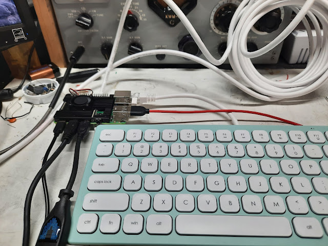
My Hermes Lite 2.0 is small and so is a Raspberry Pi4 -- and together even smaller when the Hermes Lite 2.0 is 100 feet away from the RPi4.

My 100-foot chunk of Cat 6 cable (less than $10 from Lauren Sanchez's boyfriend, Bezos) arrived yesterday, and I did just that -- put one hundred feet of separation between the two units. It works!


RPi4


Mini Keyboard


17-inch Monitor


At the operating position is a 17-inch monitor, a keyboard and mouse, the RPi4 and a headset/mic. About 100-feet away (by cabling) is the Hermes Lite 2.0 and a 100-watt Solid State Amp. This is all a result of recent technology advancements.

I often say that in 1959 a 100-watt transmitter was two racks of equipment with one rack being just the power supplies. The Heathkit DX 100 was a huge step up as the 100 watts was in a single box -- still hefty by today's standards. My 100 watts on all bands and all modes weighs maybe 15-20 pounds including the Samlex switching power supply.

But the real impact of the tests from yesterday is that I can have the RPI4/Monitor, keyboard/mouse and headset/mic be located anywhere in my home and be on the air. A 100-foot tether gives a wide option. This also addresses the summer heat and winter cold issues with a garage shack. If I want the Big Boy Signal on the air, I can even have the SB200 in line and still remotely controlled by the RPI4.

For some SDR will never happen as you really can't see or touch much of the hardware like you can with the Glue Stick PTO. For others an absolute understanding of the why of every resistor or cap is crucial which is not possible with the FPGA in the SDR. Still others (me) think of technology like LEGO blocks to be fitted and assembled is more of the challenge. SDR does require more out of the box thinking and often plowing some new fields. But that is why our hobby is such a large tent -- contests, operating, antennas and even homebrew.

TYGNYB -- The political dynamic is rapidly changing and tuning in to the events of the next 100 days will certainly take away from radio time.

73's
Pete N6QW

July 28, 2024. Another choice for a small box SDR.

Covid19 did some strange things to us as a nation. In my case I actually saved a bit of money! That seems like a weird statement considering toilet paper shot up in price! Let me "splain".


The XYL prior to her move to the Board and Care always needed to be out. Like out to lunch and out to the shopping mall. I think I did 100,000 miles on her Transport Chair. That all changed with Covid19. Thus less $$$ spent on gas, meals out and tips. My radio fund grew by a modest amount and was literally burning a hole in my pocket when I spotted this jewel the Multus Proficio


Just Released the Multus Proficio MKII


It took about a year to save up for the MKI which I have, and that was about $400. The MKII is about $475 fully built.

The MKII has some improvements which I think plays to the CW aficionados and the usual upgrades. Multus has their own SDR software, but the radio will work with HDSDR and I even had my Proficio MKI mostly working on a RPI4 using QUISK. 

The Multus Proficio is a bit larger than the Hermes Lite 2.0 but operates the same bands and modes. I think I see a few more watts out (7 versus 5) from the Proficio. BUT the Multus as of now does not handshake with SDR Console or Thetis s0 you might not need that 50-inch Monitor.

Telling is that the lower costing SDR boxes with the high-end software makes for some real competition -- $400 to 500 versus $2K -3K. 

Believe it or not I have a 100 watt CCI amp and that will drive my SB200 to 600 watts out on 20M all from a Multus located 100 feet from an operating position (like inside the house that has AC in summer and heat in winter)!

Keep an eye out for even more of these type boxes as a choice for a next place to flash the plastic.

BTW Multus also has a line of Linear RF Amps to put some "shoes" on their basic rigs and I think they are also releasing a new amplifier deck. Check their website.

TYGNYB.  In this highly charged political season this indeed is sage advice. 

73's
Pete N6QW

Disclaimer I have no connection with Multus and am just a purchaser of their hardware.

July 27 2024. A versatile addition to your shack

I get bombarded with those buy me adds including one I got for a McClaren custom automobile at only $400K. But for 0.001% of that cost ($400 bucks) you can have this jewel.


A 5-Watt SDR Transceiver

The Hermes Lite 2.0 is truly a marvel in its own right, with its small size and rich features. All Band thru HF and all Mode is only the starting place as I have it running on a wired network in my home using a $20 Network Switch. 

With some Cat 6 cable and a variety of computers the HL2 can be literally everywhere in my home. Some have managed a wireless latch up so now out by the pool with the laptop having QSO's -- and the HL2 nowhere in sight. That is a tough choice -- pool bunnies in bikinis or a 20M DX opening!

The BEST part is that it will run on a host of software packages including QUISK, Openhdsdr, Encore and Thetis. The latter two are the uptown packages used with the high end SDR radios. I have it running on both Linux and Windows Computers all the way from an RPi4 to a Big Box Desktop converted to Linux Mint 20, with a couple of Windows machines also in the mix.

But its real value has been as a test instrument.   It will let you see 384 kHz of spectrum and for HF that is most of the bands. I often use it for crystal testing as I can distinguish down to 1 Hz various crystal frequencies. It can be used as a VNA and gives a good look at carrier suppression in a homebrew rig. The binaural audio reception is a bit nerve racking but in split operation you can hear two different QSO's at the same time.

The HL2 is sold by Makerfab and is a complete board but you also need the N2ADR LPF board and the case plus shipping from DHL you are cruising close to $400.

If you lack the knack don't buy this product as you do have to assemble the board inside the case, but the hard part is installing the software suites. Since it is on a network you have to add network addresses and one of the software packages is based on the FLEX radio Power SDR. 

Not for the OT's who grew up in the Analog world, but for the 12-year-olds just another day at the computer. Some knowledgeable users suggest that the HL2 with an outboard amp and the upscale free software puts you in the league of the Apache Anon and FLEX Radios. I have not tried those radios, but I can say I am really impressed how the HL2 performs especially with the more advanced software suites. Not even close is my Drake C line. 

For those who like tailored audio -- yes some of the software distributions include a built-in audio panel to independently fine tune the audio spectrum of the receiver and transmitter.  A touch of a couple of slider bars and you have moved the audio to transmit lows, mid-range and the highs.

Most of the software packages enable at least two receivers and Encore I think can do 8 receiver slices. This is where your monitor must be at least 37 inches -- 50 inches would be better. I also recommend a high-end audio amp following the HL2 so you can benefit from the 6 kHz ESSB signals emanating from NJ (do you remember W2ONV, SK).

With a Raspberry Pi4 this makes the HL2 a candidate for POTA and SOTA ops. 

TYGNYB.

73's
Pete N6QW

July 26, 2024. SWR (Standing Wave Ratio)

The last couple of posts dealt with HARDWARE to measure SWR. But why is a high SWR a BAD thing. Often quoted, a high SWR is on par with what happens when the gas gauge is almost empty.  Or as we well know, if you had a Red Ryder BB gun you will shoot your eye out! Or the cute Red Head has only a slight STD.


Basically, two impacts are: 1) max RF from your rig is not getting to the ionosphere and 2) you risk serious damage to your rig. For many hams the idea of a puny signal is a far greater impact than a smoked rig. Hey, it's just more added on the plastic. But a high SWR also can cause unwanted feedback and then your signal is not only puny, but it sounds terrible. 

Manufacturers will caution their radio can safely operate with a 2:1 SWR or never exceed a 3:1 SWR. Some radios will sense when your SWR is approaching a danger point and even have circuitry that will idle back the power to values that won't harm the radio. (Fold Back Current Limiting).

Disclaimer -- I actually never looked at the sausage making aspects of SWR calculations but always had an SWR bridge in line to tell me the values. But a hand calculation is an eye opener. I listed a link for K6JCA (two posts ago) and he provided some detailed math on the calculations. (Now I know why I used the meters.)

If I haven't screwed this up if you take the Reverse Voltage and divide it by the Forward Voltage that is a Factor that is plugged into an equation where the numerator is 1 + the Factor and the Denominator is 1 - the Factor. Pure logic shows the lowest SWR is 1 to 1 (0 Reflected power) and infinite when the Forward is the same as the Reflected as that puts a Zero in the denominator.

So (again if my calculations are correct) what is a 3:1 SWR. Let's assume the FWD = 5 Volts and the REF = 2.5 so what is the VSWR. Our Factor is 5/2.5 or 0.5. Thusly (1 + 0.5) / (1 - 0.5) = 1.5/0.5 = 3. That Buck Rogers is Rocket Science meaning 50% of your available power is being fed back into your rig and not the antenna! Are you sure you want to subject your ICOM IC7300 to a 3:1 SWR.

Now how about 5 V FWD and 0.5 V REF. Our factor is 0.5/5 or 0.1. Thus, the numerator is 1.05 and the denominator is 0.95 and the SWR is 1.10:1 

So, you get the drift -- it is hard to get a 1:1 but that is reflective that with 5V FWD and 1.667V REF that gives a 2:1 SWR. About 1/3 of the power is being back fed into the rig and not fed into the antenna.

Notionally if your SWR is greater than 1.3 to 1 you need to fix something with your antenna! This means about 0.65 V REF with 5V FWD or about 13% not going to your antenna!

Again, a bit hurried this morning so the math may be a tad off. BUT a High SWR does suggest an eventual smoked rig and not all the juice into the wire! I am surprised at how many hams do not have in line monitoring --so get or build a meter 1st thing!

TYGNYBNAINNVNA.

73's
Pete N6QW

July 25, 2024. Some "Clean Up Items"

Once again, the Amazon Phantom has struck! In yesterday's mail was a package from Amazon containing a pumice scraping stone to clean the toilet bowl.  To my benefactor I thank you, and I truly appreciate your generosity. Anyone else feeling the urge to send a pumice stone -- I am good. A gallon of 12% Hydrogen Peroxide ... OOOPS Here I am soliciting and that is not my intent. Please do not send any H202.


Now a giant plug for the G-QRP Club and the SPRAT publication. I am lucky to own a SPRAT on a STICK, which essentially is a compendium of all of the SPRAT articles going back to #1 and carried forward to the most recent all on a USB Stick. Be aware that the compendium is only as recent to when the stick was burned. 

But I did find Issue #61 on my stick which covers the Stockton Bridge in an article entitled A Bi-Directional Inline Wattmeter pp 12-16. (David Stockton, G4ZNQ). No "Digital Stuff" here just two meters. G4ZNQ's description of the circuit and its function is superb and easy to read. He actually developed this project based on some work he did in his professional career. A page from his article is shown below.


The calculation of SWR is based on the forward and reflected power and involves some math flogging.  The no calculation involved approach is to match the load to the rig to a point where there is max forward power and a minimum reflected power -- just watch the two meters!

TYGNYBNAINNVNA

73's
Pete N6QW


July 24, 2024. Some Design Thoughts

[Late Breaking News! Dean, KK4DAS now has resolved the MCU problem -- it was a library issue. Check out this link on his build and the resolution.

]

In one week, we will be looking to change the Calendar to August. Time to start thinking about a winter project. Do we channel the thinking toward something we need like a new rig for the shack or to an item of test equipment. 

If the wheel of fortune lands on test gear, then one of the most useful pieces is a SWR Bridge. In the most recent SolderSmoke Podcast (#252) Dean, KK4DAS shared some tales of woe regarding a SWR Power Meter that would be built into his homebrew SDR Bitx (SBitx) transceiver.

Essentially, Raspberry Pi 4 software poles a sensor (Stockton Bridge) and the voltage values, Forward and Reverse, are read and then massaged in software to derive an output for display on the screen. He has been wrestling this gorilla for several weeks. The issue is tilting toward a software problem with the onboard ATTiny MCU in the sensor.

Back up in the sewer for half a moment with a starting place of what is a SWR Bridge Circuit. For a more than two-word sentence from the Co-Pilot AI, check out the K6JCA Blog It does have a lot of math but will also give the clueless a clue about SWR Bridges.

One very popular bridge circuit amongst the QRP crowd is the Stockton Bridge named after a UK ham who presented this approach in a G-QRP Club SPRAT article in 1989/90. The key feature of this bridge is it can remain in line without being a dummy load and works down to very low power levels.

You are in Luck as W8DIZ (SK) in his website has kits (about $12) as well as bare boards ($4). Look for the Universal SWR Bridge.


This kit gives you two voltages, one forward and one reverse. If you simply install two meters for these readings, then you will need a magic decoder ring to translate the readings into SWR. If you are lucky enough to own a Drake W4 wattmeter it originally came with a nomograph to make that decode. Otherwise, you can create your own nomograph using an Excel Spreadsheet.

This is where a MCU and a Raspberry Pi come into the picture as the voltage readings sent to Analog pins on the R Pi can then be calculated and displayed even on a simple 16X2 LCD.

Now before you get too excited like seeing Elisabeth Hurley in a faux leopard skin bikini, the kit is only good thru HF and a max of 100 watts.

1:1 SWR

I don't have the other shoe, as yet, regarding the MCU and RPi but will endeavor to find same and share with you. For those who loathe digital stuff all you need is the kit and two meters and a bit of time with a spreadsheet. 

TYGNUBNAINNVNA.

73's
Pete N6QW

July 23, 2024. AI to the rescue -- never happen!

I have been vexed with a ring around my toilet bowl. It has given me nightmares and the supposed super toilet bowl cleaners on Amazon are a huge joke. Bezos' stuff is expensive and does nothing to remove the ring!


In desperation I turned the problem over to the micro-shaft AI Co-pilot. I spoke the question asking for recommended toilet bowl cleaners. This is no BS, as the co-pilot AI came back with a listing of recommended bowling ball cleaners. The Co-pilot AI must have been trained in China where English is not a 1st Language.


So, then I typed in the question and the #1 response was the 9th Grade Science Project answer. Start by pouring a box of Arm and Hammer Baking Soda into the bowl and let stand an hour and then dump in a bottle of Vinegar -- watch the foam devour the ring. The next steps suggest you will still have to scrub like hell with a pumice stone to lift the ring.

In an earlier foray into AI using Chat GPT, the answer was to find toilet bowl cleansers that contain a 3% solution of peroxide. I wonder if in the presence of other stuff, I have tried, the H2O2 would become an explosive mixture? On Amazon I found a 12% solution of H2O2 and that would be my 1st choice reasoning 12 is better than 3.  I hope it doesn't explode!

So, the quest goes on -- any blog readers have an answer to my question about how to have the toilet bowl ring disappear? One wise ass SOB suggested I just buy a new toilet. This one is only 6 years old.

This brings us to ham radio inquiries on the Co-Pilot. I asked what the best ham rig is out there and got responses that were for non-mainstream rigs like an Yaesu FT-60R. Then I modified the inquiry to ask best HF rigs and two listings came back for Elecraft, the KX3 and the K4D. No mention of the high-end FLEX and Apache ANON. 

Ah Ha -- you need to refine the question, so you include evaluation parameters. Next, I asked the Co-pilot AI what the best HF Ham Radio is considering IMD and cost. The answer was junk!

Eimac 3CX3000A7 (A Hi-Power RF Tube)
Elecraft K2 (noting it was not a transceiver)
Ten Tec Omni VI+ (since it also could do split operation)
ICOM IC-736 and IC-761

None of those radios (except the K2) on the list are made today and obviously many radios that actually answer the question are nowhere to be seen. We only need to look up Rob Sherwood's (NC0B) evaluation website and we can see the IMD performance from best to worst.  Of course, cost is a matter of how much headroom is still left on your credit card.

Bottom line the Co-Pilot AI deserves a place of honor right next to a Nano VNA! Not believable and gives erroneous answers!

TYGNYBNAI = Trust Your Gut Not Your Butt Nor Artificial Intelligence

73's
Pete N6QW


July 22, 2024. Power Supplies

 The all-important power supply is a lot like an antenna. Use anything and it will work! Well, that belief and statement have a good chance of starting you off on a wrong foot for both antennas and power supplies. These two elements typically are given no consideration, and the result is often poor performance of the radio.

A typical advert from a supplier who resells manufacturer overstock starts with 12VDC at 30 Amps open switcher all for $9.95 shipped. The price is certainly less than a Big Mac Meal at Mickey D's but should also give rise to an acid stomach. Too Good To Be True has a prophetic ring to it!

Power supplies commonly used with solid state equipment broadly fall into two categories: 1) Linear Supplies and 2) Switchers.

The Linear supplies are the old transformer rectifier kind and are often heavy. I have a Astron 35 Amp Linear supply you never want to drop on your toe. A Switcher uses that old back EMF principle to take the decay of a pulsed inductor field to create a series of high frequency pulses that are rectified into DC. 

Switching frequencies may be as high as 50kHz and that is a problem. The issue of 50kHz frequency is much like sitting next to a spark gap transmitter. I had a homebrew SDR radio installed in a computer I refurbished and all along the spectrum was a blip every 50 kHz. One thing I didn't change was the computer switching power supply -- the culprit. I could also hear that computer switcher on my KWM-2. 

The switchers, often open frame, are not shielded, and value engineering has minimized components that would mitigate the hash! A 360-Watt DC supply for $9.95.


For my QRP SDR radios I use a 5 Amp Linear supply from Pyramid available from Lauren Sanchez's boyfriend (Bezos). About $50.


Note about 5000 purchasers have given it a 5 Star rating. I bought mine a couple years ago and it was around $38. I use this and do not worry about noise.

But there are some switchers that pass the smell test and the 13.8 VDC @30 Amps Samlex Switcher is at the other end cost wise with a clean output. Inching toward $200. Small too!


In another failure by me was to buy this 0-30VDC at 10-amp switcher that had features like LCD display, coarse and fine voltage/current adjust as well as current limit. I made a poor assumption since it was in a metal case and lot more than $9.95 that it would be clean. A scope on the output quickly proved that was a bad choice.


So, from my vantage point unless you head for a high end Samlex then a 5-to-10-amp Linear supply is a good choice for a bench supply costing about 1/2 the Samlex price.   

An additional consideration is a linear variable supply where I homebrewed one of those that I use to test new circuits. Basically, I am trying to not smoke a device at power turn on. By inching forward in small voltage increments you can spot when a voltage limit is being reached before a total smoked part.

TYGNYB!

73's
Pete N6QW

July 21, 2024. The Choice of IF Frequency.

You have this insatiable urge to homebrew a SSB/CW transceiver and I mean totally homebrew! This rig will have no IC's.  (Gulp) an Analog VFO, a homebrew microphone and even a home constructed case. The 12 pole QER Crystal Filter, of course homebrewed, is suddenly a decision point. No, the decision is not about 12 poles but what frequency? Did I mention this will be your first ever homebrew project.


Of all of these pieces indeed the IF Filter Frequency is perhaps the 1st item on the critical path. The McCoy Silver Sentinel or Golden Guardian Filters were some of the 1st commercial 9 MHz Crystal Filters. The 9 MHz filter was popular in the single conversion 80/20 rigs because a 5MHz VFO yields two bands, although you would need two BFO crystals. 

Had you used a 5 MHz Filter and 9 MHz VFO then because of sideband inversion only one BFO crystal is needed to give USB on 20M and LSB on 80M.

The 9 MHz filter is seen a lot in homebrew and commercial radios (Ten Tec). This all worked pretty cool until new bands were added like 17M where harmonics of BFO's and VFO's operating at 9MHz are difficult to filter out of Band Pass and Low Pass Filters. Ten Tec operated their LO at 27 MHz in the Corsair I with hopes of skirting that problem on 17M.

Then there are specific filter frequencies that create major issues. The Collins 455 kHz Mechanical Filter in a single conversion frequency design is OK at 80 and 40 Meters but beyond that you have imaging problems. The Collins filter in a Dual Conversion design skirts that issue. 

Collins Mechanical Filter


In my KWM-4 the 1st Conversion is to 10.7 MHz where I used an FM Narrow Band Crystal Filter as a "roofing filter" and a second conversion stage at 10.245 MHz easily up converts from 455 kHz and likewise down converts all signals to 455 kHz in a simple ADE-1 Double Balanced Mixer with the 10.245 MHz Crystal LO. 

The FM Roofing Filter resolves one of the products out of the ADE-1. We of course have 10.245 + 0.455 results in 10.7MHz which will pass through the FM Filter But the other product 10.245 - 0.455 yields 9.79 MHz is outside the Filter Pass Band and is stopped. I mention this because you must look at all possible mixing schemes to avoid issues such as other mixing products -- do this exercise with a single conversion 455 kHz filter at 15M. 

At the other end are filters in the 25 MHz range. Friend N2COR has operating a 10/15 Meter rig using a low frequency VFO in the 3.5 MHz range to give two bands. This has been highly successful for Bill. But he does note because of the high frequency of the filter the normal flat pass band of the crystal filter is somewhat rounded. While not a showstopper it is carryon baggage with higher frequency filters.

Many homebrew crystal filter proponents seem to focus on filters in the 4 to 12 MHz range. There may be a lot of simple factors for choice of filter frequencies in this range. Cost may be a huge driver since to build a 12 Pole Filter you need to have a pool of about 50 to 100 crystals where you can find 12 whose total frequency spread is no more than 50 Hertz. While computer crystals in this range are cheap enough -- 100 crystals will still cost you about $50. 

But lurking (like the lurkers on hackaday) in the background are parameters such as frequency stability in Parts Per Million. Many of the cheap crystals have a 50PPM stability. At 1 MHz that means 50 Hz stability. But at 12 MHz that means 600 Hz and at 24 MHz is 1.2kHz. Now take that across 12 Crystals and that is a big number. Lower frequencies mitigate the issue of stability.

Some frequencies you might want to avoid are filters at 5 and 10MHz. Unless you provide in the circuitry a lot of shielding, inevitably WWV will always seem to be in the background noise.

Undertaking and understanding the "black art science" of fabricating a homebrew filter must be approached in a rigorous manner. The first piece is understanding how the crystal parameters work to make a filter. The 2nd piece is how to measure those parameters with the 3rd piece of using the parameters in a software suite to determine the coupling capacitors, the filter impedance and the matching to the real world. You also need o think of the filter form factor. The QER (Quasi Equal Ripple) topology seems to be the flavor of the month choice today, amongst filter builders. This is where having a Nano VNA if used properly can aid in the measurement of actual filter performance.

Today's journey highlights there is more to homebrewing a crystal filter and it is more than simply putting one's hand into a poke and pulling out 4 crystals and check off the box. The choice of filter frequency drives much of the rest of the design. Personally, I like 4.9152 MHz as that was good enough for Elecraft in the K2 and good enough for N6QW. That frequency does not have the baggage of 9 MHz for 17M.

TYGNYB.

73's
Pete N6QW


June 20, 2024. Small is not always good!

In yesterday's post I was babbling about a matchbox sized SSB Transceiver. I must have been suffering from the heat we have been experiencing in SoCal. Small is not always a good thing. Today's post will look at what shrinking the size down of a homebrew rig really means.


I can remember being issued a Motorla cell phone (1990's) as a part of my job. It was fat and in no way easily slipped into your pocket. Today's cell phones easily fit into any pocket in your tight designer jeans. Portability is the key operative word and so it would be with a ham rig, thus the shrink down syndrome. 

Since we are focusing on a homebrew radio, the builder has total control over the size and final configuration. 

My foray into creating a shirt pocket SSB transceiver started back in 2007. https://www.jessystems.com/morexcvrs.html


That project didn't end up being shirt pocket size but did provide some important baseline data. Somewhat reincarnated it is in a box 7X7X2 or almost 100 cubic inches. A later successful shirt pocket sized SSB Transceiver was 16 cubic inches or about 1/6 the size.

The shrinking process in part depends on technology advancement. The Xiao RP2040 is smaller than an Arduino Nano (and a lot more powerful). So that new tool takes up less space and that contributes to a reduction in size.

But let us explore some of the negatives about a size reduction. 

1. I/O -- we need panel space for controls, displays, power input, mic and audio jacks, antennas and external controls. The I/O drove the 2X2 inch front and back panels. That was the smallest I could take it. 
2. Following 1, is the minimum number of rig controls that you need. Two musts are audio and Tuning. For mic gain a 1/4 inch in diameter hole in the back panel gave access to a board mounted trimmer pot which was the mic gain. 
3. Following 2, is that compromises were made in the design to eliminate circuitry and circuit features. No AGC circuitry was included but that drove the need for an audio gain control. I also eliminated a Receiver RF Amp stage (a mistake). Later technology enabled me to add a simple BFR106 RF amp stage on a small PC board .5X1 inch and literally a tenth of an inch high. It was tack soldered to the mainboard. A big improvement driven by SMD technology.
4. Method of building was dramatically changed. Thanks to a tip from KB1GMX, I used a base plate with a vertical spline so I could have circuits on the base plate and then small circuit boards vertically mounted to the spline. Pass through holes facilitated wiring of the various boards. This is creativity driven and more than a flat piece of pine board.
5. Heat and Unwanted Feedback were major issues! Jam stuff together and that reduces circuit cooling. Jam stuff together and you have set that stage for unwanted coupling and possibilities for oscillation. There was a lot of cut and try to get the right board placement.
6. Often forgotten in both commercial and homebrew rigs is the need for service. Where you have jam packed everything in every space -- when it comes time for servicing problems like subthreshold conduction, you are stuck. In fact, that reminds me of what happened with V1 of the Shirt Pocket Transceiver. I was probing with a screwdriver and because of everything being so close -- a giant short, a giant mushroom cloud over the bench and a giant number of smoked parts! It was not possible to rebuild it back to original and the salvaged pieces were built into another (larger) rig. 
7. FFS (Fat Finger Syndrome) is an issue with small control knobs. The original Shirt Pocket rig used a crystal switched Super VXO tuned with a 10K pot. Separating stations took a deft hand not unlike that required for success in the back seat of the 57VW Beetle. 
8. The add on devices. The 16 cubic inches had no room for a speaker and thus earphone operation or an external speaker to bring along. There was no nice digital display, so the dial scale markings were only approximate.
9. The tough question was it worth the shrink down. Yes, it is a novelty and has made contacts but a bit bigger would have been better.


TYGNYB.

73's
Pete N6QW

July 19, 2024. With a doff of the cap to VK3YE, Peter Parker.

VK3YE, Peter Parker has churned out a mountain sized number of projects that are a  three-fer. The Knobless Wonder is a great example where Peter has designed a 40M SSB transceiver that is a simple design, easy to build and works well (that's 3).

[Of note, if you are into DSB radios then VK3YE has the subject totally covered.]

In the 1st video where QSO's are being recorded VK3YE's has a terribly noisy environment as a routine challenge. The 2nd video was shot at the beach and thus you get a much better feel of how good this radio works.


Essentially Peter has a designed a 10 Transistor SSB transceiver whereby choosing the right crystals builds the Crystal Filter at the operating frequency (7.159MHz). So, no LO is needed, and the incoming signal is fed to the IF. Thus, no Knob needed for the main tuning dial ~ Knobless! Most of the supporting transistors are the BC458 (NPN) and the Driver and Final are BD139's.


VK3YE"s Knobless Wonder 


A Build from JA2GQP


The BFO can be set above or below to give you LSB or USB. True it is a one channel radio but so is FT-8. The closest frequency that I could find for non-SMT crystals two years ago at Digi-Key was 7.200 MHz but are now obsolete. Surface mount 40M crystals can be found at Mouser. The 7.2 MHz ten-piece price is 21 cents. They also have 7.168 and 7.1505 MHz in surface mount stocked. I also see non-SMT crystals at Mouser for 7.175MHz. (Short can)
 
Could this be an opportunity to build a match box sized SSB transceiver to be featured on Hackaday (bragging rights). Forget Hackaday as the lurker detractors would complain it only operates on one frequency. The 20M Color Burst crystals are on 14.318 MHz and lots of POTA stations operate near there. So that is another opportunity.
 
About two years ago I did buy from Digi-Key the 7.2 MHz crystals and so that might be an interesting prototype project for this winter. The BFR106, a very rugged surface mount device, looks like a good fit for use on a project like this. This could be the answer to the Michigan Mighty Mite! My twizzle on this project would be to change the IF Module from 4 transistors to two and using micro relays steer the signals in one direction through the filter.

A HB to HB QRP QSO


TYGNYB 

73's
Pete N6QW


June 18, 2024. Needed a filler since we were participating in a Solder Smoke Podcast this morning!

Needed a filler this morning since I was with Bill, N2CQR and Dean, KK4DAS participating in a new soldersmoke podcast soon to be seen on You Tube video screens in your neighborhood. 


73's

Pete N6QW

July 17, 2024. Six trash bags and two cardboard boxes.

I had a wakeup call yesterday and while not all ham radio related, a significant part of my "personal vision" is. 

How can we be so consumed with the more? You know more radios, more power output, more antennas, more gadgets and even more charged on the plastic.

Crystal Test Oscillator Gadget


We are ever consumed by reading the ads for new radios from the Far East. Some hams even subscribe (for $59) to getting these ads via a download from a purported radio amateurs journal. Often new stuff shows up on our phones without our even doing a search. Thank you, AI. 

I am terribly guilty of looking at Amazon for new gadgets I can share with the blog readers. Shudder, I am also an eBay junkie -- trying to spot the $50 boat anchor rig that will test my technical skills at a reincarnation. 

It is summertime and time for ham fests. A blog reader from NJ (yes, it is state and more than Tony Soprano) sent a link to a recent ham fest. I enjoyed looking at all of the stuff for sale. Some of that stuff I have been looking to find for years. Lots of parts that could be made into "leenear amps". Many high-power antenna tuners from Murch and EF Johnson were spotted. Good thing I didn't go -- I would be cash poor.

Read the mail (eavesdrop on QSO's) and you hear two subject areas often discussed: new radio equipment just acquired and the current illness of the week (or weak). Politics also seems to be in current vogue these days. 

But the equipment is not the cheap stuff McGee. If it is a younger ham with a family spending $10K for new radio toys seems at odds with when I had a young family -- there just wasn't that kind of money in my budget. Once the kids were gone and I was retired -- a bit more money but still $10K for ham gear was not something easily done. I guess building my own gear came from how to do it by spending only $100. 

It also seems that the new equipment acquisition is a revolving door as often you will hear from hams who have bought three or four new spendy rigs in a span of 1 year. Yes, they lost money, but they have tried them all.

Why can't we just be satisfied with the dozen or so radios we all have. What drives us to buy or build another radio? Can we not just take time to use what we have in the shack? Is it consumerism that drives us or keeping up with the Jonses? Or is it the much sought after bragging rights -- look at me I built a SSB transceiver that fits in a shirt pocket (large size pocket please). 

Now to six trash bags and two carboard boxes. There was a passing at the Board and Care facility yesterday. It was a recent resident who had been there only a month and seemed OK but is now gone. Outside on the front porch were her possessions awaiting pick up by her family. Her whole life was now in 6 bags and two boxes. This stuff will not follow her to her final resting place, and neither will that $10K new radio you just had to have.

We are here on earth for just a short time. Use that time wisely and temper the hobby with the real important things in life like family and loved ones*. This may be the time to fix the family discord problems and get everyone into the fold. Each day is precious, and we should cherish our life gift. All of us will end up with six trash bags and two boxes -- but the real question is the path we take during our lifetime.

TYGNYB.

73's
Pete N6QW

*Just In Case you have both an XYL and GF


Neutralization.

The word neutralization has many interesting meanings. For Mafia Dons, like the Tony Soprano types, the word has the definition of simply el...