Monday, July 10, 2017

A New Line of Transceivers ~ DifX

A New Transceiver on the Air!

* Some updates added on 7/11, 7/12, 7/13, 7/14, 7/15, 7/16, 7/22


A New "Juliano Blue" in the Wings?


I frequently have several transceivers in work at any one time and eventually some event occurs that causes me to actually finish off one of the rigs. It was really hot this past weekend in SoCal and so that was the triggering event -- there is just something cool about working in a garage that is running a hot 90 degrees F or for those who use the " other standard " we're talking 32.2 Degrees C.


Here are some highlights of this DifX [Different from a Bitx]:

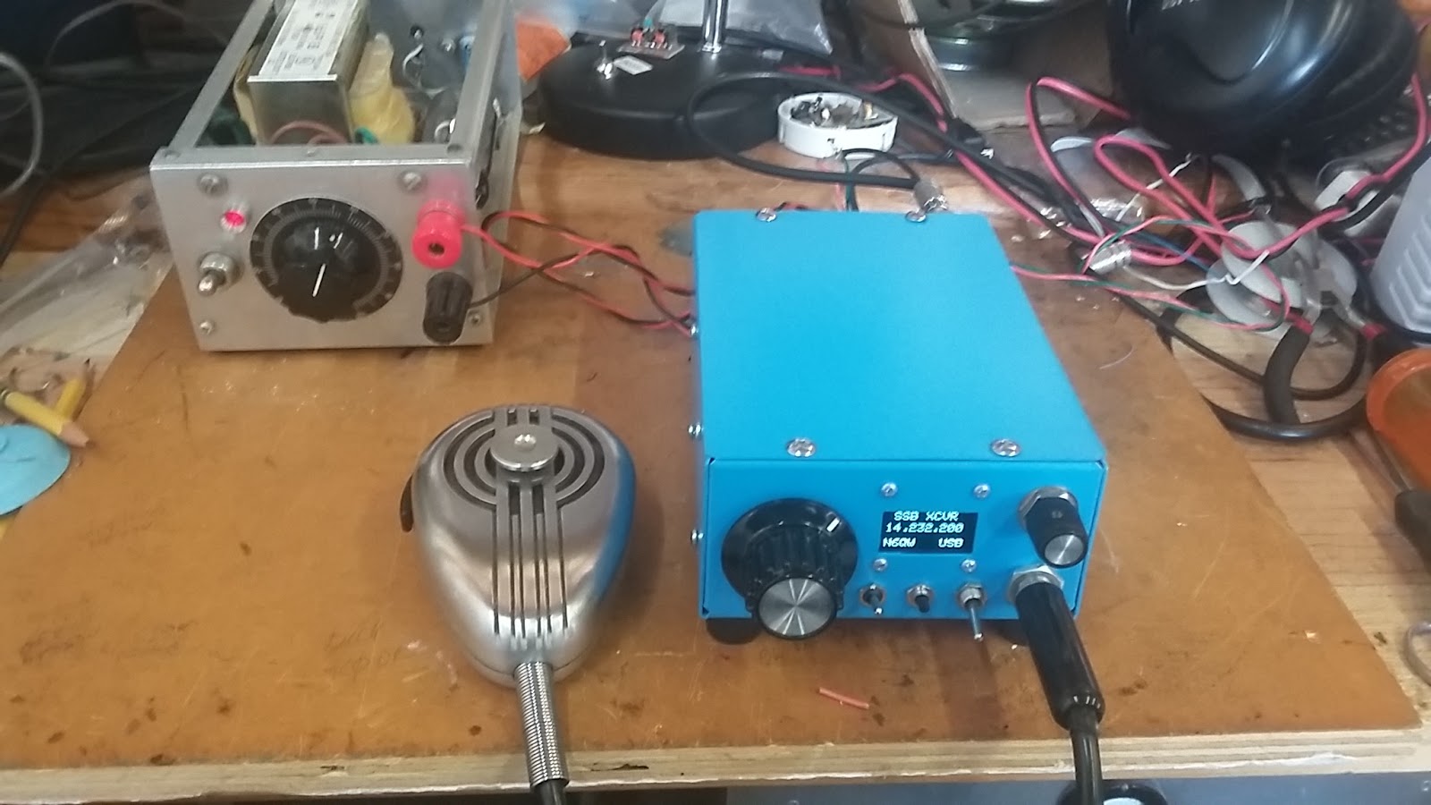
  1. The size is 4X6 by 2 inches high. [For reference purposes the Bitx40 board is 25 square inches not including the display and controls.] I wouldn't call this micro-sized but Mini-Sized is probably OK. A bit of fudging here as I happened to have a 4X6X2 inch aluminum chassis that became the case enclosure. I bought this chassis years ago with the plan for a one "toob" CW transmitter --but who does CW anymore? To get more of a feel of the size of this power house look at the photo below and the relative size as compared to my venerable D-104 Microphone. This says a lot when your rig IS smaller than the Microphone.
  2. For the most part the circuits used are ones applied by me in other projects although this is only the third time I have used MMIC amplifiers and seeing how well they work will now become the standard for me.
  3. The rig operates on 20 Meters as that seems to offer plenty of activity (even DX) and there are less SDR police and old buzzard nets like on 40 Meters. Yes these are my contemporaries.
  4. The main IF uses  a 9.0 MHz Crystal Filter from INRAD [Model 351] and the Bi-directional amplifiers used for the Rx RF Amp and Tx Pre-driver are two, diode steered and relay switched, AG-303-86G MMIC amplifiers. Going into this stage I used a 2 dB pad and this has really added to the overall stability. Lets face it --these are cramped quarters and lots of potential for unwanted feedback.
  5. The Si5351 supplies the LO and BFO and the display is a 1 Inch Square Black and White OLED. Should mention OLED noise has not been a problem. The main Microcontroller is the Arduino Nano. A little detail here is that I provided clearance in the build so that a USB connector can be plugged into this board for any program changes without removing the Nano. A small but very important detail. The default step tuning rate is 100 Hz but additional selections via the encoder push button are 1 kHz, 10 kHz and 100 kHz. This approach gives plenty of flexibility to tune the entire 20 Meter Band,
  6. The Bilateral IF Amplifiers are the 2N3904/2N3906 Plessey circuit and the RxTx Mixer is an ADE-1L as is the Product Detector / Balanced Modulator. ADE1-L = 4 dBm devices so set the output on the Si5351 to 2 ma. Note the 2N3904/2N3906 are SMD. The immediate photo below shows the Model #351 4 Pole Crystal Filter which had been in the rig for about a week. On 7/16 I replaced that with the GQRP 6 pole filter. This involved a bit of noodling and modification to the lower board and to the very top board of the three board sandwich. The GQRP Filter being taller than the Model #351, meant I had to add more spacing between the first and second boards. The top board which is the audio and microphone amplifiers had to have two electrolytic capacitor swapped out for one shorter ones. In one case a 330 Ufd was replaced with a shorter 220 in parallel with a 100 Ufd. It was a small nightmare but it is all back together and is a testament to a well stocked junk box, fifty years of building experience and throwing caution to the wind. BTW can tell the difference with the GQRP Filter. Much tighter skirts and actually more output!
  7. The Audio amp is the LM386 driven by a 2N3904 and the Microphone Amp is a single 2N3904. The RC Shaping filter for the 988 Hz Square Wave Tone coming from the Arduino is also located on this board.
  8. The next photo shows how the board was reworked and move slightly so all would fit back in the case. Note the use of the solder lugs to "collect" the board so it doesn't move and the add of the two smaller electrolytic capacitors so as the assemblies moved upward all of the boards would fit in the case.
  9. The Power Output is 5 watts via a IRF510 and the driver is the 2N3904/2N3866 standard circuit from EMRFD.  This linear amp board is about 3.5 inches long and about 1.9 inches high and fits in the rear of the chassis box. The chassis is the heat sink. Note the shield between the driver and final stage and even the DC bias stage is behind the shield. Some additional bypass caps on the IRF510 have proven to add much to the stability.
  10. Other features include USB/LSB, MOX and Tune (via a 988 Hz tone generated by the Arduino). I wonder why the Bitx40 aficionados have not added the "Tone Tune Up" to their radios? In time grasshopper, in time. Note on the display the words SSB XCVR --when you place the rig in the Tune mode the wording changes to TUNE and when the timing cycle is over it reverts back to SSB XCVR. There was a bit of trickery to make that happen and not something found on other currently popular radios. Note the size in comparison to the 1/2 used pencil.
  11. The paint is standard Juliano Blue.
Some construction notes for this project. This is a really compact rig and even the install had to be sequenced so all circuits would fit in the enclosure and could be hooked up. Unless you have experience in building circuits in tight places, it is not recommend you replicate my approach. While the circuit pieces are modular, making them fit was a real challenge. One assembly consists of three stacked circuit boards with the bottom board being the IF, front end Mixer, PD/BM stages and the middle board is the MMIC bidirectional amplifiers and the top board is the Microphone and Audio Amplifier stages. The Driver and Final are on a separate board as is the Arduino.  From the photo below you can see it is pretty jam packed into the enclosure.

The OLED noise has not been an issue so check that box. BUT what has been a constant problem is the LEAD FREE SOLDER CRAP. That solder just does not stick and is a particular problem if you are using Manhattan construction. If you are doing ultrasonic wave soldering on 408 sized SMD parts --probably OK but not OK on an IRF510. Initially there was no output from the transmitter --yep a solder connection on the base of the 2N3866 just did not stick. You end up welding the parts and not flowing the solder. This new solder is real crap!!!!!!

The proof is in the pudding and my new rig just completed its first contact with WA7ND, Rick up in Bend, OR. The report was excellent and I was running the small outboard amp so the Pout was >100 watts. Forget that QRP crap and just move on. I have had a second contact on the rig with KD5CO, Chuck in downtown Texas. I couldn't resist an additional test with the second contact --yep two after burners and the Pout > 600 watts into my two element beam. Now this can be a DX machine. So this is proof that the rig is more than a one hit wonder. Today (7/11) I had a really great QSO with Jim, KA5BDO in New Mexico and he was very complimentary of how the rig sounded. He also suggested I use the Turner Dynamic Microphone for rag chews and the D-104 for DX chasing. You can see the new rig with the Turner Dynamic Microphone in the photo below. [That new rig IS small!] Just had a QSO with KH7XS, Bill out in Hawaii running 600 Watts -- another great report. This is a DX Machine in a mere 48 Cubic Inches.

This is one superb rig and lest you forget --it is a DifX! I can't fully express the joy in putting this rig on the air and to have real QSO's with this diminutive sized box. One asks could there be more features? With a bit of more effort on packaging and the add of one DPDT toggle switch, two band operation would be possible. The only adds would be a second Band Pass Filter and a second Low Pass Filter and of course the toggle switch. If I replaced the MOX switch with a band switch then no more panel space would be required. A 40/20 Meter rig would cover the bases or maybe the 20/15 Meter bands or even a 20/10 Meter rig when the sunspots kick back up. Maybe even a 40/17 Meter rig would be your cup of tea. It is merely some code changes to the sketch.

While it may not be possible for readers of this blog to build this project in a very tight space like this 48 cubic inch chassis box -- this is a worthy transceiver project that could be successfully built on an albeit larger scale (or box). That said the smallest SSB transceiver I have ever built was 33.3% the size of this rig --16 cubic inches. Virtually all of the circuits used in the rig have been previously published on this very blog (or articles in QRP Quarterly) so the module schematics are no mystery. If some one would like the Arduino sketch send me an email to the address on my QRZ.com page.
 
Block Diagram and Some Schematics


The Finished Rig~ Another Successful DifX!


As of 7/15 I have made over a dozen contacts with this DifX rig and am very pleased with the signal reports I have received. Only one negative SDR police report regarding opposite sideband suppression being only 40 dB down. Opposite sideband suppression could be improved with a different filter but  a commercial 9.0 MHz Filter I have might not fit in this build. On 7/16, I did replace the 4 pole filter with the 6 pole GQRP filter so we now have a better filter in the rig.  The signal quality is much better on receive and I am sure likewise on transmit.

73's
Pete N6QW

Wednesday, July 5, 2017

A New Line of Transceivers ~ DifX

Homebrewing a Chassis, Cases and Enclosures

Make your Rig Look as good as it Sounds!

 
There is just something about a rig that has that finished look when it has a painted case. Yes, it is something that came out of your garage or workshop but there is no reason why it can't look "finished". Long ago I adopted "Juliano Blue" and perhaps there was an unconscious bent to that decision based on my very early solid state experiments with the distinctively Blue CK722 transistor. Go Blue!
 
Of late I am not satisfied with a project unless it resides in a Blue Case --a Juliano Blue Case. So how do you get to the point of homebrewing a chassis, cases or enclosures. The first part is the right tools --no you don't need a $250 K CNC mill but for about $50 you can purchase a bench type metal break from Harbor Freight.

When I bought mine about 10 years ag they could be had for about $25. The type I have is 18 Inches long. The next thing you need is some stout metal bars in various lengths. The tool from Harbor Freight comes with an 18 inch bending bar. By using smaller bending bars in the 4, 6 and 8 inch range you now have a box break where you can easily make 6 X 8 inch chassis boxes -- thus the smaller bending bars.
 
For a chassis I make it in three pieces. Two pieces are "L" shaped and the final piece is the to cover. The two "L" shaped pieces are formed with ears so you can bolt/fasten to the pieces. Fastening also include "pop riveting". Two Chassis' are shown below one is a general purpose chassis and the other was one made for a transmitter power supply. Believe it or not most of the materials are galvanized metal available from Home Depot. The power supply chassis shows the "L" structure of the pieces and make for a very rigid chassis. The Sheet metal is very inexpensive and with a couple of homebrew chassis bulds you will recover the cost of the metal break.


In the photo above there is a trick to making these "L" section and it all has to do with the sequence of the bends. Excellent measuring skills are needed to pull this off and laying out the bends and cuts has to be done carefully. this is even extended to when the metal is in a flat state and that is when I actually drilled the holes. I have a stock of manila folders and so my first step is to make the part out of the manila folder stock. This in essence is a template. The first pieces bent are the top and bottom lips which are about 1/2 inch wide. At the location of the bend line I cut a 45 degree angle of material to the bend line on both the top and bottom sections. This when this is bent at a 90 degree ange the pieces meet up perfectly. Both sections are identical only in one of the pieces the end section is bent up at 90 degrees at each end. This is where the smaller bending bars come into play. Essentially an end of the bending bar is placed perpendicular to the bend line and the larger piece is bent upward. For normal operation the bending bar is "C Clamped" to the bed of the metal break and so with the smaller bars you can make boxes. the following two photos give a bit more detail of what is described here.


Now I would like to spend some time on how I build cases using angle stock readily available from Home Depot. The metal plate can be ordered from a company called "On Line Metals"


Yes this is an old project when I actually built analog VFO's as evidenced by the National Velvet Vernier. As soon as I started using the Si5351 I gave this rig away since I didn't want any evidence in my shack of an analog VFO. The aluminum angle stock makes for a very rigid structure and you can easily screw sheet metal to the sides and top.


The next critical issue is one of materials. Use what you have or think out of the box (enclosure). Sheet metal (versus aluminum) is readily available and inexpensive. Home Depot is a good source. I also have used single sided copper PC Board which often can be had a really good price. ABC Fab up in New Hampshire (eBay) sells various packages of boards. Recently I bought 18 pieces of 4X6 inch heavy duty board for about $1 a board --delivered. I also bought some 8.5 Inch by 12 inch board from the same source and two of my rigs have that for a base plate. One ham shared he found a source for large square tin cans which he cut open and flattened. Also check out computer shops as you can often find CD/DVD units which are defunct but its the case you want. Cookie tins are another great case source. So open your mind to the possibilities.
 
Oh --it is not a real case unless it is painted Juliano Blue!!!!!!
 
73's
Pete N6QW


Thursday, June 22, 2017

A New Line of Transceivers ~ DifX

Transceiver Architecture 2.24


Back to the Dual Conversion DifX Build

 
6/25/2017 ~ Working Field Day (at QRP level) with the 20M Shirt Pocket SSB Transceiver. At 16 cubic inches --smaller than a Bitx ! I actually made QSO's with this transceiver and it is a testament to good things come in small packages. Definitely a DifX.
 
 
73's
Pete N6QW


6/23/2017 ~ See video at the bottom for more MMIC Applications 

Now that I was able to resolve the Crystal Filter that will be used in the second IF (it is not a Dishal nor any other form of homebrew filter) I have turned my attention to the issue of various amplifier stages that are used elsewhere in the rig. One such circuit is the bidirectional amplifier board I developed where there are two amplifier circuits comprised of a single 2N3904 in each leg. One leg is the receiver RF amplifier stage and the second leg is the Transmit Pre-driver stage. Relay switching is used to direct the signals in/out of the board -- a total of three relays.
 
While the 2N3904's are cheap, the relays are not! While the stage was broad band there were issues of making the gain constant over a range of 30 MHz (160 to 10 Meters). Since most of my rigs are single band units or perhaps two bands like 20/40 Meters this was not so much of a problem.
 
So in noodling the problem to have broad band amplifiers stages that are constant gain, are 50 Ohms, involve minimum switching (no more than one relay) and are termination insensitive. While you could use the Hayward/Kopski Termination Insensitive Amplifiers -- I wanted this to be a Pete design and not use the work of others.
 
My noodling took me back to 2010 and my very first article in QRP Quarterly where I used MMIC (Microwave Monolithic Integrated Circuit) amplifier blocks. The project was a 20 Meter MMIC based QRP SSB transceiver. A pair of MMIC amplifiers are diode steered so that they are bilateral (operating in two directions depending on which amp is powered on and steered for the proper mode). Yes Alice (or Virginia) it has a Digital VFO,
 

(Interesting note in that same issue we have G3UUR Analyzing Crystal Filters)

 
The MMIC device selected was the TriQuint (Watkins Johnson) AG-303-86G, This device is good to 6 GHz and has a fixed gain of 20 dB with a Z in/out of 50 Ohms and operates from 5 VDC. It also is termination insensitive, Did I also mention they work quite well.
 
Thus it was an easy decision to once again employ the MMIC amp and we have a board operating with a test transceiver. The alternative for those who don't want to enjoy using MMIC's in your next rig then you can always use the Hayward/Kopski TIA amps. Shown below is a board that was just installed in the transceiver that was recently used to evaluate the 128X32 OLED noise issues.


BTW I did have several conversations with TriQuint and they provided information about the use of the 1N3070 diodes as the "best choice" over the 1N914 or 1N4148. The actual building of this bilateral stage will present construction problems in that the MMIC's are surface mount and really small. It will be difficult to build this amp using Manhattan techniques. So while the benefits are superb, the construction may well beyond the skill/capability of those who have never done this type of homebrew construction. In the last 7 years the price of the MMIC's used has increased significantly so that may be a factor in your decision but my having a stock of the devices makes it a non-issue for me.
 
As you are perhaps gathering,  the Dual Conversion DifX will have features and functionality not found in other currently popular designs.
 
For those sitting on the edge of your chairs regarding the detail of second IF filter --patience grasshopper (for those who remember the Kung FU TV series). Oh I will tell you it is not 9.0 MHz.

Below is a video of MMIC's (four of them) used in a 40M CW transceiver built about the same time as the 20M MMIC SSB Transceiver. I do not know of many other transceivers that employed MMIC's in various transceiver stages. Perhaps another tip of the spear from N6QW.

 
A video from 2017


A video from 2010


73's
Pete N6QW

Friday, June 16, 2017

A New Line of Transceivers ~ DifX

Transceiver Architecture 2.23


Commercial and Surplus Crystal Filters

 
6/20/2017 ~ Short diversion -- OLED noise with a 128X32 OLED Blue Display


Believe it or not this test is important to an upcoming project that will soon be revealed.
 
73's
Pete N6QW

 
6/18/2017 ~ In the original post I mentioned that I saw three German Filters on a board for sale from Israel but did not know much about them. Thanks to one of the regular blog readers (Thanks Jim), we now have info on these filters and from what I can see they appear to be symmetrical which is important if they are installed in a bilateral circuit such as the Termination Insensitive Amps and the Z in/out is 1 K which is a 20:1 match to 50 Ohms. A 9 turn to 2 turn matching transformer gets you close 9^2 = 81 and 2^2 = 4. 81/4 = 20.25.
 
The good news is that they are 8 pole filters which will really tighten up the skirts and resolve the "feathering" issue complained about by one of the 40 Meter SDR police and cited in the post. Thank again Jim for the info and the plot of one of the filters taken "bare" without any matching which  would affect the ripple content in the pass band. If that ripple is smoothed your are looking at 60 dB
rejection and pretty narrow skirts.
 
Don't rely on my analysis but  for some this might be a good buy and you get an AM filter too! This is definitely not a Dishal homebrew filter and would be hard to replicate in a cold, dimly lit garage with the only tools being a cheap VOM and an 80 Watt RS soldering iron.

I just bought a board with the three filters -- $34 shipped and that gives me three filters.

 
Pete N6QW


Having sworn off Dishal and other homebrew filters there has to be some alternatives for those who would like to homebrew a rig. The reasons are many  for not homebrewing a filter and chief among these is that it is difficult to achieve consistent results from these somewhat arcane processes without the benefit of an extensive amount of test equipment. Anyone who tells you they did it with just a VOM is Fake News. Now if you just want to try your hand at it --by all means build a filter.
 
But with the advent of the SDR radios and those who lurk around 40 Meters looking for aberrant signals, there is a strong possibility you will get a report that some one has spotted energy above 2800 Hz (especially on 60M) or that your filter is feathering. (OK try to figure that one out.) Yes a homebrew filter will let you enjoy the experience of making a rig where you literally built everything by hand. But I would bet that in most cases the homebrew filter that results unless you are extremely lucky will not match a commercial filter.
 
So OK where can one buy a reasonably priced SSB filter? One place is the GQRP Club. Join GQRP, become a SPRAT subscriber and buy a high quality filter for about 12 Pound plus shipping. At a $2  to 1 Pound exchange rate --about $30 with shipping puts one of those jewels in your hands. Many of my rigs have this filter. In fact two W7ZOI designed rigs have two such filters in each rig. The IF is 9.0 MHz and works very well for most applications save 17 Meters. Below is that filter in the Zia Transceiver built in 2014 which uses the Hayward/Kopski Termination Insensitive Amplifiers. The photo right below shows another GQRP filter installed in the LM373 Rig.


For the same amount of money INRAD sells a 4 pole Filter Kit --also on 9.0 MHz. I have two of those filters and they work very well. It is their model # 351. The Crystals are color coded and come with both SMD and Leaded Caps so you can pick your method of building the kit. Below is the #351 in a 2017 project implemented with the SMD caps.


Just yesterday I toured eBay looking at commercial/surplus filters. Wow some one from downtown Serbia is selling Elecraft SSB filters for an amazing price. There are also filters from Kenwood, Yaesu and Icom radios. Some are pricey but some are really at a very good price.
 
There were several Heathkit filters and some listed starting at $10. I have used a Heathkit filter in a transceiver and it works very well. The only problem --it is rather large. The filter IF is a 3.395 MHz and so this lends itself to a dual conversion approach. In the photo below the signals ahead of this board were converted to frequencies in the 8.8 MHz range. The PTO (lifted from a Ten Tec Triton IV) operating a 5 MHz converted the signals to the IF at 3.395 MHz using the TUF-1 on that board. The relay on the board enabled adding AGC to the IF or ALC. The device is a DGM 3N209 in a circuit developed by G4GXO in Sprat 128 --it is bilateral! In the upper right hand corner is a diode ring modulator/demodulator that had both resistive and capacitive balance. That is not something you find in many homebrew rigs. I built this in 2009.
 
 
But just as I saw some really good filters there were some questionable ones. There were several boards from Israel showing three German filters on one board. The price was OK --it is just that I didn't immediately recognize the filters. More research needed here.
 
The 8.8 MHz (or so) Kenwood Filters look like a good fit with a 45 MHz 1st IF. Many of the commercial filters are 2.6 KHz wide and so would give better results on received audio as well has having a Hi Fi sounding signal on transmit with all of the benefits or presence, brightness, color, with great lows and highs.
 
Frequently with a homebrew filter you will get tons of complaints about having pinched or restricted audio --typically form those operators using SDR radios with 72 Inch LCD screens. So they can really see your signal!!!!
 
So expand your horizon's and think beyond homebrew filters -- it avoids a lot of work that frequently results in a marginal filter that unless you are extremely lucky will have a difficult time competing with a $30 or less commercial filter. Oh -- the Heathkit Z in/out = 2K Ohms, the GQRP is 500 Ohms and the INRAD #351 is 200 Ohms. Pretty easy to match and a known quantity!

BTW I bought this filter after finding out more of the specifications and  this now lends more weight to my argument -- I just bought three filters for $30 and $4 shipping. These filters are better (being 8 pole) than any 4 or 6 pole Dishal filters. After purchasing the board I got a prod from eBay essentially saying buyers who purchased this board also bought Si5351's --so there are individuals out there who are already on this path. (6/18/2017 N6QW)

That is the other bit of good news. In the past having the filter without the matching BFO crystals was a huge problem. No more fellow homebrewer's. With the Si5351 --you simply change the frequency in the sketch and you are off and running with a new filter. Hooray --that is a problem no longer.
 
73's
Pete N6QW

On November 3rd, 2026, America became great again!

The Mid-Term Elections and the resounding replacement of politicians of one political persuasion is a datapoint that shows it is the will of...