Monday, December 2, 2019

Bitx40: ~ Replacing the Raduino with the N6QW controller!

Say What: Replacing the Bitx40 Raduino?

12-07-2019 ~ Pearl Harbor Day

Let us not forget what happened 78 years ago today. On a sad note there are but three remaining survivors of the original USS Arizona crew and only one will be attending the commemoration ceremony.


Many have sacrificed to make this the Land of the Free and the Home of the Brave! 

*****


I have now added switching of an linear amplifier to the PTT circuit so I can run 600 Watts with my "reworked" Bitx40.  Two 1N4148 diodes and a 12 VDC SPST relay make it all happen. Running a bit more power does help.

My latest project now on my website...

http://www.n6qw.com/The_Paesano.html


12-04-2019:


I call my Bitx40 "Maggie May" since she has been passed around a bit and before transmitting I specifically looked at the Bitx40 documentation. Shazam -- The bias was at Zero and not set to 100 Ma, and there was no drive as such. Fixing those two provided 10 Watts of solid power output on 40M. I cranked it back a bit since it would see some heavy duty cycle operation on WSPR. 

My offer stands: any one wanting to dump their Bitx40 -- a crisp $10 Bill and shipping costs from a US address is my offer. C'mon guys rid yourself of that former play toy and let N6QW work his magic. 

Send me an email to the address on the masthead if you would like the sketch code. 

N6QW, Pete the Radio Genius


12-03-2019 ~ Digital Modes with the Bitx40 and the N6QW Controller.


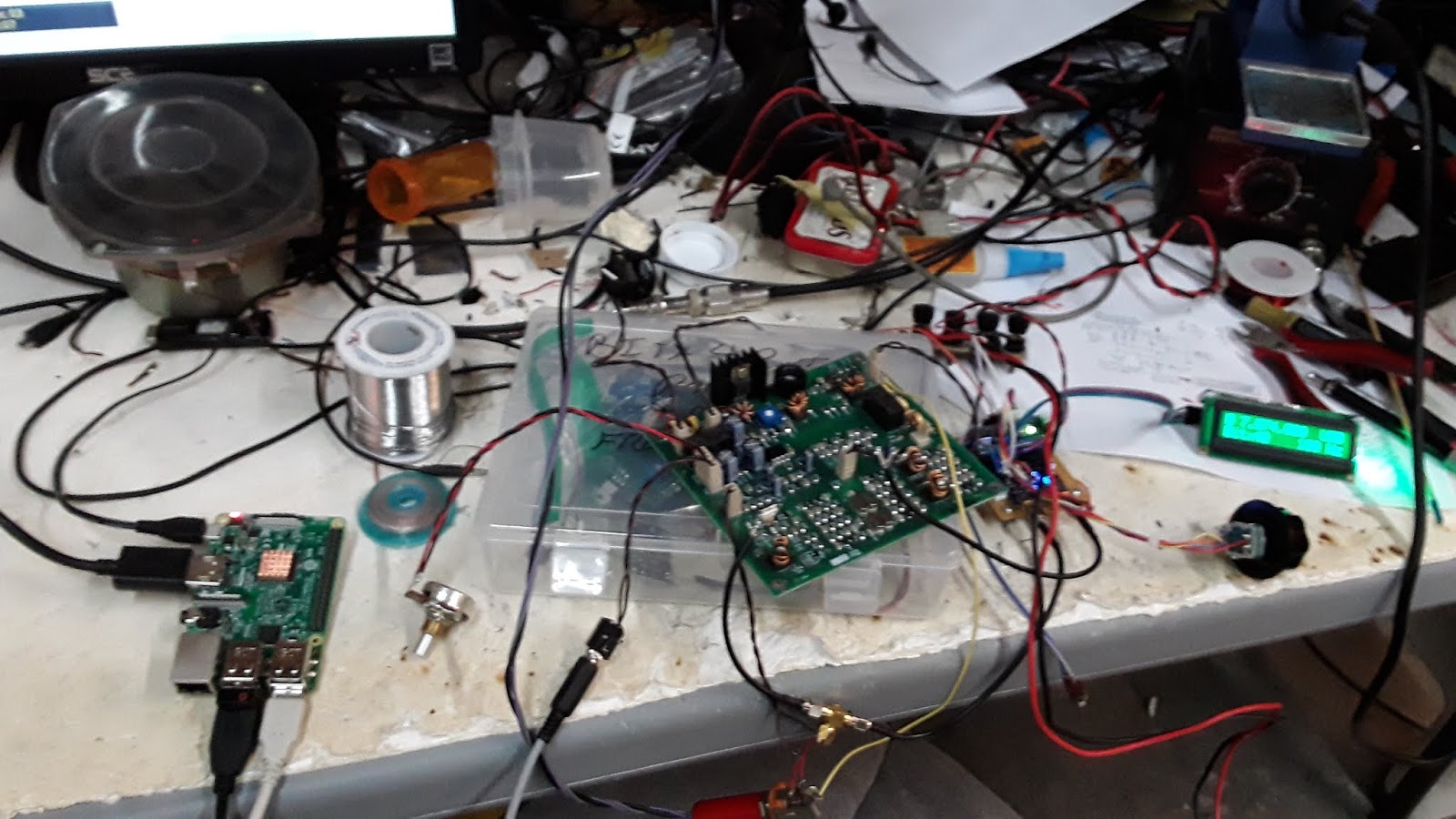
Raspberry Pi3 and (not seen) N6QW Digi Controller being used with the Bitx40 and N6QW's Raduino Replacement.

A couple of key comments 


  1. This shows I must be close on the USB offset as both FT-8 and the WSPR were dialed in on their normal frequencies
  2. I did not transmit on either WSPR or FT-8 as you must modify the Bitx40 Microphone input circuit. The Bitx40 uses an electret microphone which typically has a DC bias voltage on the input pin. As I did on The Paesano, I added a Data Port -which is nothing more than a 3.5 mm stereo jack that has a 10 NF cap in series with the microphone port to provide DC Isolation. That has yet to be done. Works perfectly on transmit see last chart.
  3. So for those of you who have "put away" your Bitx40, with a few changes you can do "The Digi Dance" with your rig.
  4. My offer is still open if you would like to dump your Bitx40 -- a crisp $10 bill plus shipping and I will take it off your hands.
  5. WSPR on the Bitx40 with N6QW Arduino Controller.

  6. After three hours both transmitting and receiving


The Bitx40 being heard In Brazil and Sout Africa! Nice!

Stay tuned to this space for more exciting Bitx40 Modifications -- may be even 6 Meter SSB.


Pete, Radio Genius


73's

Pete N6QW


12-02-2019

Is this like blasphemy, heresy or on par with the Ukrainian Bribery scandal? No, it is none of those just a practical matter. 

In a recent Soldersmoke Podcast #215 the fact was made known that the Bitx40 was no longer in production. I then said if anyone wants to sell me one for about $10 contact me. That offer is still on the table!

Well my good friend N2CQR sent me one that had been passed around a bit (you know like Maggie May and the high school football team). Well when I connected all I soon discovered that Raduino was not providing any RF. The pot tuning also left me wondering even if it did work would I be happy.

So I took some parts, took some software and when you know stuff you can do stuff!

I started 1st with a 5 MHz PTO from a Drake TR-7 and that was to quickly establish that the main circuit board worked and was the Raduino the only problem. That was accomplished. 

Next was to get a basic Nano and Si5351 to produce the LO signal which was also to prove that my LO was correct and that a first stab at the BFO frequency was at least in the ball park. Keep in mind that not all Bitx40's are exactly alike. I think initially depending on Uma's crystal sorting there could be as much as 3 BFO frequencies.

Finally after passing the LO test I added the BFO. This test proved that the LSB BFO is very close but I may need to tweak the USB -- next phase. To introduce the BFO signal (since the LO is done through a two pin header) I had to uncouple the crystal and inject the BFO into the base of the former oscillator transistor. I am using a custom made for Pete Si5351 PLL's that has isolating caps on the outputs built into the board. Your may not so include a 10 NF on your output other wise you may smoke the transistor or your Si5351. Add the BFO signal at the junction of R102, C104.


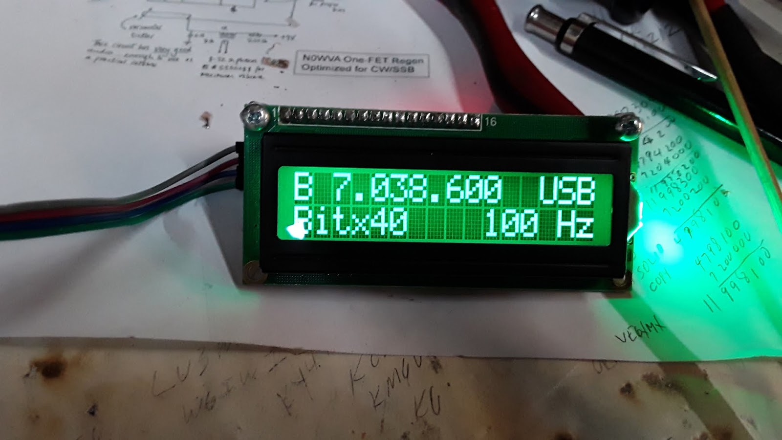
Recapping my Raduino Replacement has 2 VFO's, USB/LSB and a Tune Tone. Did I mention the cool Green LCD?

The long term plan is a 6 Meter SSB transceiver using an outboard Transverter. Stay tuned and try to catch up.


Pete N6QW


Thursday, October 24, 2019

A letter sent to DX Engineering

Are we being manipulated by the Ham Radio Manufacturers?

Here is a letter that was sent to DX Engineering?


If after reading this you have similar views --why not drop K3LR a note at the DX Engineering website "Contact Us" tab. I am sure he would love to hear from others in the ham homebrew community who like me see $4K for a Appliance Box as being out of step with our true ham roots which are now over 100 years old!

10/26/2019 ~ PPS (Pre Post Script). 

When you have the innovative and experimental mindset, then it is possible to add some new technology to fix problems with older radios. One does not learn that by knowing the 3000 menus in the IC7300. A Ten Tec Model 540 had a completely broken dial cord mechanism. Yes. radios used to have dial cord mechanisms. 


The message here is "when you know stuff, you can do stuff"! Working Contests and Operating may not give you the skill sets to pull this off. Watch the video...


October 23, 2019

Dear Tim, K3LR


Thank you for sending me the latest DX Engineering catalog which clearly displays radios and equipment that are simply not affordable for an OT like me who lives on a fixed retirement income.  Spending $4K for a radio is simply not in my budget; but that does not mean I am not on the air with some very modern equipment!


Your lead piece on page two sums it up quite nicely –endless possibilities. Recently I “homebrewed” a fully functional SDR transceiver for about $150. The reason this is possible is that there is so much amazing and cheap technology that makes this SDR rig a reality. Notice I didn’t say radio as that has implications of an appliance box! 


For a computer I am using a $35 Raspberry Pi3, the Sound Card was $15, and the USB Frequency Controller was $30. A lot of the critical hardware was obtained as free engineering samples and includes two ADE-1’s. Yes, it’s on a bread board.


The display can be an older LED TV that has an HDMI port and of course a keyboard and mouse. The driver stage is a 2N2219 and the final is the IRF510. The SDR Software is a free download from N2ADR known as Quisk.


Above is the typical Quisk spectrum and waterfall display just like the Big Boys with the $5K radios; but mine cost me $150
.
This now leads me to the remainder of your piece about Elmer’s. Seem like things have really shifted over the 60 years I have been licensed. Today’s Elmer seems to serve the function of what is the best antenna to purchase from your company, or how to navigate the 3000+ menus on the IC7300. In my day Elmer’s were the technical resource for knowing each and every component in a circuit and how it is applied, and the “why” it is there. Oh, that’s right now you send in a box top and get an extra class license and then spend thousands for a rig you have no clue how to operate.

It is with interest that your Elmer goals seem to follow what to buy, how to operate in contests and a friendly voice that says buy a FTdx101D. No where do I see a fostering working with and/or building your own radio using the latest technology. I know you have done marketing analysis to identify the demographic with the most $$$ and the new crop of rigs are priced accordingly. 

In a recent vintage ARRL Bulletin it was a position of the IARU that hams are hams for two reasons: Contests and Operating. Certainly, that is good for your business; but that position ignores what hams of my vintage did and do today. They were innovators and experimenters. Just look at Gerald Youngblood who took the concept of SDR and now he along with Raytheon are developing the next generation of communications systems (SDR Based) for the US Air Force. Suppose if K5SDR only wanted to operate and do contests? Side note, Raytheon used to be a ham equipment manufacturer. If you have ever happened to look at the nameplate on a late Model of the famous SBE transceivers – yes a unit of Raytheon.

My real point is that you might want to consider offering more “homebrew rig” kits so that we continue to foster the innovation. Besides you might actually hook a few more customers for the big box appliance stuff.

Now below is an example of where I built a solid-state version of the Collins KWM-2 which I call the KWM-4. Not every one could pull this off – but here is another endless possibility.


This is a multiband, dual conversion (10.7 MHz and 455 kHz) all solid state QRP rig. It involved some critical thinking and with the exception of the remote keypad and the Digi VFO the whole design and construction was done by me. As you can well guess I spend lots of time on the fabrication side, little time operating and no time contesting.

Since DX Engineering has become such a Big Gun in our hobby and regrettably the ARRL only wants to sell advertising for unaffordable radios, perhaps this is a time to be a true Elmer and foster and reincarnate the original “homebrew” spirit of our hobby. I invite you to visit my QRZ.com webpage and my three websites. www.jessystems.com , www.n6qw.com and www.n6qwradiogenius.us. Hopefully you will see I have built more than one radio.

73’s
Pete N6QW


A Bit Of Wizardry -- When You Know Stuff, You Can Do Stuff. My Extra call goes back to 1977 in case any one wondered.

Friday, October 4, 2019

There is just Something about Innovative Mechanical Engineering

Mechanical Engineering in our Radios, Rigs and RADIGS


Being hams, we often think about the electronic hardware in our rigs. Does it have an IRF510 in the Output or a Real RF Device like a RD06HHF1? Is it being "Run" with a digital VFO or one of those drifty, shifty Analog boxes.

BUT we often forget that some of these beloved radios rely heavily on our brother Mechanical Engineers to make it all play. You only need to look at James Millen who did all of the ME on the HRO receivers. Or pop the hood on that Collins R390A and savor the mechanical tuning mechanisms. Perhaps you overlooked the same in your KWM-2 or Drake TR-4. The ganged tuning of various networks is a marvel. Hey don't forget the SBE-33/34 and the "Geneva" Turret tuning arrangement.

But there is a special place in my shack for those really "cool guys" at Ten Tec. If you perhaps have some earlier Ten Tec radios like the 505, 509 or 540 that string driven dial system was pure Mechanical Engineering as was their PTO's. Can you imagine -- you could rebuild your PTO right at your kitchen table -- pretty clever.

But at times some of the Mechanical Engineering was hidden behind the panel and we simply used it without giving it a second thought. The Model 540 has a band switch located in the lower left hand corner of the radio. Actually it is THREE band switches with two visible on the front panel. When you put the main band switch on 10 meters you have an additional 4 position switch that is engaged to give you four band segments. But there is a third hidden band switch that is engaged as you change bands. Here is that Mechanical Engineering stuff at work

Before you gulp -- this is a Model 540 that was upgraded by me to a Model 544 and was the subject of a QRP Quarterly article in 2013. 


When we think about the Model 540 and the principal band switch you must think about what that switch is really doing. It has many jobs/functions. 

The way the frequency scheme of the  Model 540 works is to have a singular fixed VFO range operating at 5 to 5.5 Megahertz --yes you guessed it a 9 MHz IF. But to work the various bands this basic VFO signal is mixed with various crystal frequencies to produce the LO Signals that results in the 9 MHz IF --it is a single conversion radio.

Now we have all seen the 9 MHz IF and 5 MHz VFO that gives you two bands -- add the IF and VFO and it is 20 Meters. Subtract the VFO from the IF and you have 80 Meters. But you do have to pay attention to any possibility of sideband inversion.

But Ten Tec used  for all bands except 20 Meters a VFO signal that is crystal mixed to give an injection frequency above the incoming signal on 80/40 Meters and then for 20 Meters and above the LO injection is below the incoming with no crystal mixing on 20 Meters.

So this mysterious hidden band switch is THE mechanism that "on's" the crystal mixing for the various bands. 

Another Mechanical Engineering problem -- packaging. The Ten Tec Model 540 and Model 544 were very "desk top" friendly having a very small compact footprint. Thus a very long shaft could engage many band switch segments to engage multi-function circuits. But you are faced with the trade off of long band switch size and compact footprint.

Another function of that band switch was to switch in various LOW PASS Filter Networks following the final amplifier "brick". Along the way other circuits are switched into play with changing of the band switch.

Did I mention yet another Mechanical Engineering problem -- circuit shielding and isolation. That crystal oscillator and mixer circuit were shielded--yes in a shielded box there is also a MC1496 DBM that mixes the Crystal Frequency with the VFO to produce the proper injection frequency. Another wafer on that third band switch adds some filtering to the output of the driver stage ahead of the final amplifier brick. Believe it or not -- that wafer is mounted on the back side of the shielded box, right adjacent to the driver board.

Oh more ME stuff -- all of the major circuit boards have through board pin connections that on the bottom end plug into chassis mounted sockets and actually protrude through the top side -- this give you access to literally hundreds of test points. Smart Mechanical Engineering!

Back to our third hidden band switch. So if this switch is not on the same shaft as the main band switch how is it engaged. Enter a piece of brilliant Mechanical Engineering which I call "a slider crank mechanism". Two mechanical linkages affixed to the main tuning shaft essentially clock the third band switch so that when you place the main band switch on 40 Meters the Crystal Oscillator puts in line a 11 MHz crystal so the output when mixed with the 5 MHz VFO output a 16 MHz injection signal results. When that injection signal is mixed with the incoming signal at 7 MHz the result is 9 MHz at the IF. 

BTW if you look at the Model 540 BFO, a single BFO frequency will result in the "Normal" sidebands for all of the ham bands and with a bit of capacitor padding will shift the BFO frequency to the "Reverse" sideband. Ten Tec does not call them USB and LSB. I keep digressing

Here is a photo of that slider crank mechanism. Essentially what you have is two pieces of metal coat hanger with a loop formed at each end. These loops fit around a drum like spool assembly so that as you clock the band switch the coat hanger material is free to move around the spool; but the push pull action moves the third band switch in unison with the main band switch. If you don't know that the spool assembly comes apart and you somehow get the metal, bars out of the spool -- they simply cannot be fed back in place without removing the cap


The reason I mention this is that I have a project on the bench where the "slider crank mechanism" was in shambles, the dial cord was chewed up and it was obvious some non-engineer maybe one of those BTE's tried to "fix" something without knowing what they were doing. Pretty obvious who they voted for in the last election.

The metal bars were pretty bent up and I did a bit of straightening. The interesting engineering aspects of the nylon assemblies that fit on the two shafts they are molded so that the fit only one way on the half moon shafts of the two band switches and the bonus --there are really small set screws that further lock the nylon pieces to the two shafts. 

Good thing I have acquired many small Allen wrenches. BTW the same Allen wrench that works with the main tuning knob will work with these set screws on the nylon assemblies. This is a long term project and you will be amazed at the final product.

Pete N6QW


Tuesday, September 3, 2019

Dipping the Toe into the World of CW

A New Found Opportunity--Arduino + CW!

The Left Coast Loafer CW Transceiver


Hey John Bolton now that you have some free time, have you considered getting a ham ticket?

A New Definition for MAGA

More And Greater Avarice. 

Maybe the wrong guy just got fired yesterday!


*****************************************
9/7/2019 ~ CW Output Across 50 Ohms


*****************************************
9/6/2019
More Tidbits for your amusement and amazement!

So here are a couple of "tricks" I would like to share with you.


  1. First is how to have sidetone. Well with my super duper DPDT TR switch I added a 470 Ohm 1 watt resistor and a 1N4007 diode. The 470 Ohm connects on one end to the voltage contact that supplies the Transmit voltage. The other end is connected to the Anode end of the diode. The Cathode end is then connected to the contact that receives juice on Receive. Thus on receive no voltage is fed back to the transmit side; but when in transmit voltage is fed to the receiver. The 470 Ohm dropping resistor is a 2 watt unit which essentially operates the receiver  at about half voltage and the audio is not very loud. With the scheme I am actually listening to the transmitted signal -- thus sidetone.
  2. Next is the method of turning CLK2 ON/OFF for transmit. I am not actually keying the clock; but during the transmit sequence CLK2 is continuously on and the transmit RF chain is keyed through a 2N2905 PNP "keying" transistor. You do hear a bit of backwave in the headphones but that is not transmitted. So back again to my DPDT TR switch and voltage is taken off the transmit contact and fed to the Base of a 2N3904 through a 1K 1/4 watt resistor. The 2N3904 Collector is connected to Pin 4 on the Arduino Nano which has been set HIGH in software. The Emitter is grounded. So when voltage is applied to the base via the 1K resistor the transistor switches and essentially Pin 4 is made LOW which turns ON CLK2. Throwing the DPDT back to receive stops the CLK2 (OFF) and all is normal.
  3. A further refinement as found in SSDRA (not seen in EMRFD) is an electronic TR switch using a NE555 and a few diodes. This would automate the sending so all you do is hit the key and the rest is automatic.

What started out as a bunch of scrap/surplus circuit modules is now a full functioning CW transceiver. You just got to love all of this technology.


73's
Pete N6QW

*****************************************
9/5/2019

Something new learned today!!!!!!!!


This is the very 1st time I am using all three clocks on the Si5351. and it has been an excellent learning experience for me that I want to share with you.

So CLK(0) is supplying the LO signal at around 5 MHz and CLK(1) is supplying the BFO signals ( 12.096 MHz +/-) for CWU and CWL. Should mention I used an AD9850 stock oscillator to find the proper BFO frequencies and then modified the code with those frequencies. So the grand plan was how to use CLK(2) in such a way that it spit out the proper frequency for the transmitter including a plus/minus 600 Hz offset. 

Setting the third clock to give that frequency output so that it automatically tracked the received frequency was not too difficult. The nut to crack was to only have that third frequency output only while transmitting. 

My code senses a LOW condition on Pin 4 and when that happens and depending on whether you have CWL or CWU engaged the transmitted frequency is +/- 600 Hz from the received frequency, the third clock is turned on and the display shows that frequency. The problem I initially had was that once turned on -- it stayed on! There were some references to how to do it and they were not clear nor was the data sheet helpful. That is when I spotted something in the si5351.h file --the ah ha moment.

With a simple line of code and a change in one coefficient it is possible to turn ON and turn OFF a clock --in software/

Turn ON:     si5351.clock_enable(SI5351_CLK2, 1);
Turn OFF:   si5351.clock_enable(SI5351_CLK2, 0);

(OK you missed it -- the "1" turns it on and the "0" turns it off.)

So my code senses if Pin 4 is LOW and if so then turn ON the CLK2. If it is not LOW then turn it OFF. This is the standard If Else regime. You also have to blank out the frequency in the else part of the code. Here is the code

 void CheckCW() {
         
                 digitalRead(4);
                 if(digitalRead(4) == LOW){
                 si5351.clock_enable(SI5351_CLK2, 1);
                
                 si5351.set_freq( bfo+O-rx2, 0, SI5351_CLK2);
                 ucg.setFont(ucg_font_ncenR14_tr);
                 ucg.setColor(255, 255, 0);
                 ucg.setPrintPos(15,80); 
                 ucg.print(bfo+O-rx2);


         }
            else{
              
                si5351.clock_enable(SI5351_CLK2, 0);
        
               
                 ucg.setColor(0, 0, 0);
                 ucg.setPrintPos(15,80); 
                 ucg.println(bfo+O-rx2);
            }


 }


Note: O is the offset variable and is set by a selection in the code. If you select CWU then O = +600 and if you select CWL then O = -600. 


Now the Code for CWU CWL Selection:

There still may need to be some tweaking to get CWU CWL in the right relationship which only requires changing the signs on the O = 600 or O = -600. But the display does change from having the transmitted signal above or below the received signal by 600 Hertz. If you don't like 600 Hertz the change the 600 to what ever you like such as 800 or maybe 500. The code below is based on my filter frequency which is above the signal frequency. If you use a different filter frequency below the incoming (homebrew, heathkit or early Yaesu)  then you will have to diddle with the U or L and the offset. The photos below are to merely show that the transmitted frequency is either above or below the received frequency --my scheme works! The code now makes CWL = -600 and CWU + 600. On the Air tests will help me affirm that is the correct sequence. If not just changes the two signs of the 600 and you would be there. Gets a bit confusing. 

 void CheckSB(){
     

     if(digitalRead(SW)){  //If SW is true do the following.
       bfo = 12098500L; 
       si5351.set_freq( bfo, 0, SI5351_CLK1);
       {
          O = +600; // + Offset Value
     
        ucg.setFont(ucg_font_ncenR12_tr); 
        ucg.setColor(0, 0, 0);
        ucg.setPrintPos(42,98);
        ucg.println("CWU");
      
        ucg.setFont(ucg_font_ncenR12_tr);
        ucg.setColor(255,10, 200);
        ucg.setPrintPos(3,98); 
        ucg.println("CWL");}
    
     }
      else{                //if not, do this.


          bfo = 12096500L;
          O =  -600; // - Offset value
       
          si5351.set_freq( bfo, 0, SI5351_CLK1);
          ucg.setFont(ucg_font_ncenR12_tr); 
          ucg.setColor(0, 0, 0);
          ucg.setPrintPos(3,98);
          ucg.println("CWL");
      
          ucg.setFont(ucg_font_ncenR12_tr);
          ucg.setColor(255, 10, 200);
          ucg.setPrintPos(42,98); 
          ucg.println("CWU");
          }
         
      }


I still have some wiring to accomplish. When I use my exotic DPDT switch for TR it will also close a relay to provide a LOW condition at Pin #4. When you go to Receive then the clock is turned OFF and the screen is blank where the transmit frequency was showing. 

I bypassed the crystal oscillator transistor and straight into the EMRFD board. I get over 500 MW and my SS amp now registers 50 watts out. Shades of my Johnson Adventurer (on steroids). A few more checks and we may actually have to make a contact.

After I get things cleaned up I will post the code on my website www.n6qw.com.

If I had thought how to do this before --it might even be possible to build CW into most of my homebrew SSB transceivers  using a method I used in my KWM-4. There the generated CW signal bypasses the mechanical filter and dumps the CW signal right into the transmit mixer chain. In the KWM-4 it is fixed so that it receives only on USB (the two schematics below show the KWM-4). 

Now much of the work would be done with the Arduino/Si5351  and a simple keyed buffer amp. Look at the dates on these schematics -- almost 7 years ago I had a scheme for SSB and CW in a homebrew double conversion multiband transceiver. OK I will say it -- ahead of its time!


Pete, N6QW
******************************************
9/4/2019


I have received some inquiries about the "innards" of the Left Coast Loafer CW Transceiver and will over time will supply some technical data about the rig. The rest is up to you.


Firstly this rig just sort of happened like spontaneous construction. I had some spare and/or obsolete circuit board modules in the junk box and the next thing you know -- we have a transceiver. 

Note this is essentially a Trans / Receiver and the common element is the Digital VFO which generates the LO and BFO signals for the receiver as well as a secondary VFO that offsets the received frequency by + or - 600 hertz for the transmitter. It is not a true transceiver (sharing many common elements) like I usually build


  • The Audio amplifier board was originally in the LBS transceiver project. I never liked the discrete components amplifiers -- too many parts and I really have no need or desire to know what every components does in an audio amp circuit. But I did have the board. One premise of the LBS was to only use discrete components.
  • The main receiver board is comprised of a homebrew  DBM, a healthy (2N5109) post mixer amplifier and a three pole 12.096 MHz crystal filter thence followed by a BF991 product detector. That board also had a J310 Crystal Oscillator for the BFO. The board size was maybe 3 x 4 inches. It was initially built again as a part of the development effort for the LBS project. [The LBS project was a two part article in QRP Quarterly authored by myself and Ben KK6FUT (now AI6YR)  -- LBS = Let's Build Something.] Needless to say --it works pretty well.
  • The Rx RF amp stage is just a single "hot biased" 2N2219 and is untuned. In fact there are no Band Pass Filters in the Rx section -- probably one would help with out of band signals --but this is a "loafer" build.
  • The transmitter, initially crystal controlled on one frequency (7.030) in its original form was an oscillator stage in a 30M CW transceiver which also was published in QRP Quarterly. That transceiver has been cannibalized and the parts and boards have found their way into many of my current SSB transceivers. This board has a 2N3904 crystal oscillator essentially followed by the EMRFD stage (2N3904/2N3866) and develops about 1/2 watt. An afterburner delivers about 15 to 20 watts to the antenna. The transmitter will now be driven by one of the outputs from the Si5351 and is offset by +/- 600 Hertz from the received frequency.
  • My initial construction had a 5 MHz VFO operating the receiver and the single crystal for the Transmitter. Now with the Arduino/Si5351/Display we have the Rx LO and BFO and the Tx VFO all in one neat package.
  • For now we will use manual switch over from Rx to Tx but the Arduino will be reprogrammed so that you hit the key and it is automatic --you are on the air. 
  • Other possibilities drawing upon the collaborative efforts with AI6YR and use the articles we penned for QRP Quarterly for the CW Sender and incorporate a keyboard for sending CW. It may require the use of a Mega 2560 --but that is just more space on the breadboard.
  • The Box has been opened...


*****************************************

9/3/2019

This post is a result of too much Temperature (90F), too much Tequila and too much Time on my hands.


In the process of creating a new rig, I actually ended up with a spare Arduino Nano and Si5351. This was a fatal error for now I had a driving desire to couple these two with my new found color OLED Displays --an worse yet to integrate these three items into a simple CW transceiver.


An earlier foray in August with again the terrible three's (Temperature, Tequila and Time) I built an analog VFO controlled VFO receiver with a 3 pole 12.096 MHz crystal filter and then mated that with a QRP 7.030 MHz Crystal Controlled transmitter. So now how to make the lash up work with the Arduino & Si5351.


The Easy Part 1st!

That is the beauty of having lots of code snippets as it now becomes possible to port over code to new projects without having to start with a clean sheet of paper.

My initial configuration is to have the following:


  1.  The LO will run around 5 MHz and mated with a 12.096 MHz IF results in signals in the 40 Meter band. So the code was changed so that CLK(0) would spit out the LO signals and the display would read the 40 Meter Band
  2. The crystal BFO would be initially kept for the testing purposes so a BFO frequency as such (typically CLK(2)) would not be generated. However CLK(2) would only be activated on transmit would take the BFO (IF) frequency and subtract the LO but would add 600 Hz as the offset. I call that CWU so that the transmitted signals would always be 600 Hz higher than the received frequency. With additional code, a simple switch would give you CWL which then would cause the transmitted signal to be 600 Hz lower in frequency. Again initial testing will be at the +600 Hz offset.
  3. The first photo below shows the display in the receive condition with a default boot up of 7.030. The second photo shows the transmitter engaged (a Pin goes low on the Arduino) and the transmit frequency is generated via CLK(2) at 600 Hz higher in frequency. Unkey the pin and CLK(2) stops and only the recei9ved frequency is displayed. Initial tuning tests with the encoder indeed shows that the transmitted frequency tracks the received frequency by +600 Hz. Pretty cool.


So the next steps are as follows:


  1. Mate the Arduino/Si5351/Display with just the receiver section and run the various test such as birdies, noise, sensitivity etc.
  2. The output of the CLK(2) is not a sinewave and so some cleanup might be (very likely will be) needed. I also need to determine how to replace the crystal with the signal from CLK(2) and also address the signal level which might require a booster amp.
  3. The current configuration has a DPDT switch that changes the voltage to the Rx and TX as well as switch the antenna from Rx to Tx. This may need to be a bit more refined. so that you hit the key and all is automatic.
  4. Finally this may be an opportunity to try CLK(1) which would supply the BFO signal thereby eliminating the Crystal BFO.

Note this is a measured approach so that changes are made in such a way as to test, evaluate and refine any modifications being made.


I just hope it gets cool so I can get back to some serious other SSB SDR work. Stay Tuned!


73's

Pete N6Qw

Chick Magnets

POTA, The new Chick Magnet (Dream Version)! POTA, The new Chick Magnet (Reality Version)! It is all about Contests and Operating. (Images AI...