Here We Go Again -- More Transceivers
October 17, 2020 ~ From This to This

The Emperor should be very careful what he says about Locking People Up. Karma is a bitch and it will be interesting to see what plays out.
73's
Pete N6QW
October 13, 2020
Update on my uSDX Transceiver project.
I found the project interesting and has a lot of inbred creativity. That said I have not been successful in achieving a quality output signal in SSB. I am perhaps not alone and for those who have given glowing reports of 5X9 signals with amazing audio, there are two explanations.
The first is that they are smoking some of that funny stuff that is a major cash crop here on the left coast and/or the second they have no clue of what a good quality SSB signals should sound like.
My signal quality on Transmit is distorted, it is wideband and the opposite sideband suppression is not evident. I think the FCC under normal times would question my using this project to transmit SSB.
Knowing what I know today I would not have even begun to build that radio. So if you are thinking about proceeding then think again long and hard before jumping on board. Read all the threads about Transmitting SSB (which by the way I was the 1st to post that inquiry).
Here is a way to think about the uSDX...
It is sort of like the Fan Dancer of the 1930's who has the audience on the edge of their seats with her tantalizing moves and then they discover “she” is not a woman.
At Best the uSDX in my opinion is a "Wanna Be" SSB Transceiver! Perhaps never to be!
73's
Pete N6QW
***********************
October 12, 2020
Christopher Columbus Day ~ That Italian Dude that Discovered America.
Since I had time I worked on the Balanced Modulator and Microphone Amp Board for #50. It was a bit of a challenge to fit all the electronics on the one piece of scrap board I had --but we made it.

Along the left side is the 2N3904 Microphone amp and toward the right side is the MC1496 Balanced Modulator. The Black Trimmer is the mic gain and the White is the Balance Pot.
BTW -- using the single sided copper vector board -- there is only one wire that is crossed over. This is where tribal knowledge and lots of skill enable one to make high quality PC Boards. It is the yellow wire that supplies power to the 3 K resistor connected to Pin 12 on the MC1496. That connection serves as an anchor point for providing source power to the board during transmit. Because of my expert skills at layout it is also a common power source point for the microphone amplifier. Ya got to say it: Nice Board!


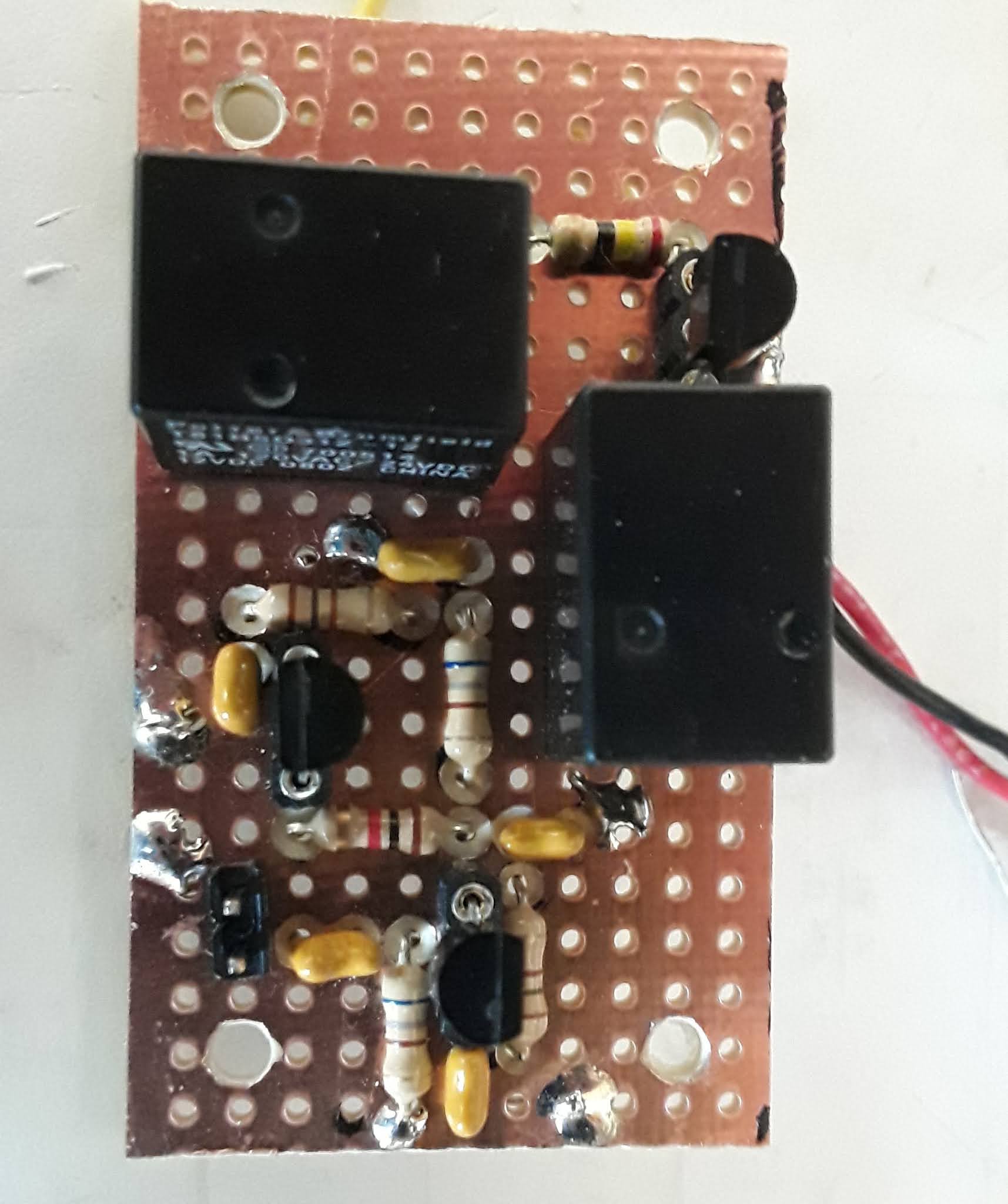
Above is the Plessey circuit that includes the Bi-Lateral 2N3906/2N3904 Amp stages and the two Relays, plus 8 VDC Voltage Regulator. The 2N3906 is used as the Receiver RF Amplifier Stage and the 2N3904 as the Transmit Pre-Driver (Bottom Transistor). The relay along the right hand edge is used to route the signals to the Plessey Stage from the Antenna (on Receive) to the Transmit Linear Amplifier stages (on Transmit).
The relay at the top normally has the two 100 Ohm Emitter resistors connected to 8 VDC (On Receive) which means the 2N3906 is active and the signals pass from the Right (Antenna) through the relay, amplified and to the Left (and on to theBPF). When this top relay is engaged (On Transmit) then both 100 Ohm Emitter Resistors are grounded. This now makes the 2N3904 active so that RF passes from the BPF (Left) is amplified and then routed to the follow on Transmit stages through the relay on the right hand edge.
Test Time Tomorrow. The SCW is taking a life form.
73's
Pete N6QW
My #49, a kit no less, has proven to be a huge disappointment to me! I think it is an uneven playing field; but in time we shall see.
With such a disappointment you are left to having to chose between drowning myself in Italian comfort food or building another transceiver -- it was an easy choice --- BOTH.
About a month ago (three transceivers ago) I built a Direct Conversion Receiver using the MC1496. It has worked well and God willing will be formally published. All I can say is if you want the article and details then you best be a member of the G-QRP Club!
As well as that DCR worked you have the annoying problem of the opposite sideband. It drove me nuts -- I know of course how to rid yourself what you don't want. Thus was born the idea of a Bilateral IF Module. Now I had some junk boards that contained a Homebrew Double Balanced Mixer. JIC you can search youtube and you will see three videos of how to do that from N6QW (me). That same board contained a 3 Pole Crystal Filter Operating at 12.096 MHz
There were some other former circuits on that board that I simply ripped off with an 80 Watt Radio Shack Soldering Iron operating at 500 C. I was left with just the DBM and the 3 Pole filter. I had a another small sub-board that had one of those marvelous Plessey Amps installed complete with a microminiature switching relay. I could solder this board to the DBM/Filter Board. With a piece of scrap Single Sided Copper Vector Board I built a second Plessey Amp.
So the circuit is an input from the RF Amp (2N3906) and the BPF to the DBM. The LO ( operating at either 19 MHz or 5 MHz for the sideband switching) on to the 1st Plessey Amp and thence through the Filter on to the 2nd Plessey Amp. From that Board on to the MC1496 as the IF input and the LO originally to the MC1496 was now swapped for a BFO operating at 12.096200 MHz.

73's
Pete N6QW


