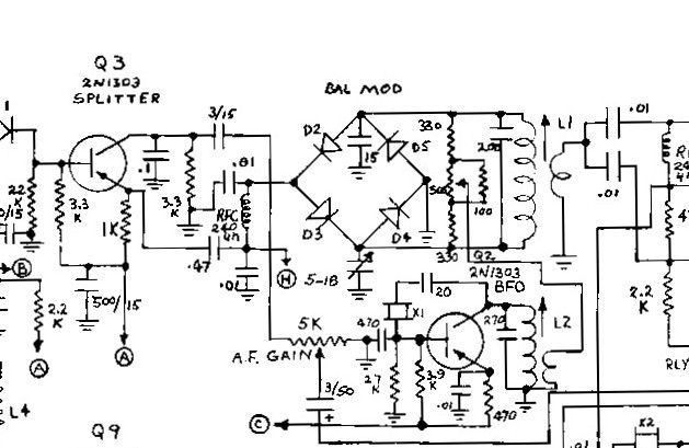
Before investing a huge time sink in building / reworking the FP-200 power supply for Project X, I wanted to assure myself that everything short of the Final Amp is working!
To date most of my energy has been spent on cleanup, fixing some of the mechanical issues and in general that the receiver is more or less working. To that end the Receiver works pretty well on 40 and 20 Meters. The 80M band is a work in progress. I then looked at could Project X generate an SSB signal. That was my trip down the rabbit hole yesterday.
First question: Does it generate SSB signals? That is a hard question to answer as it depends.
The CIO (Carrier Insertion Oscillator) and Balanced Modulator are textbook and no rocket science here. The Bal Mod is a Diode Ring and includes both phase and amplitude balance. The CIO at 5.173500 MHz regrettably includes no "netting" the frequency so that with crystal aging it is a crapshoot to place the carrier at just the right place on the crystal filter passband. An issue but not the root cause of what I am about to describe.
The SSB generation is "variable" to best describe the results. On 20 and 40M it does generate SSB but on 20M you see more of the carrier present in the SSB envelope.
On 40M you get the closest of a typical carrier null (adjusting both for phase and amplitude) almost a flat line and nice sharp Christmas tree pattern on the DSO. It sounds good on an outboard external receiver. Incidentally, 40M is the best on Receive.
On 80M you see a RF Signal Filling the Screen and very little SSB envelope visually or audibly.
So what is causing that condition? My first foray into a solution was to use 40M to adjust the Bal Mod both for phase and amplitude (the 500 Ohm pot and 5-18pF Trimmer). Note the only input signals for any band are the audio input from the mic amp and the carrier input at 5.173500 Megahertz. There is no band switching of anything. The resultant signal going into L1 is just that and not band dependent.
But the place where the mystery may have a test point is in the transmit mixer stage. Today I would put an ADE-1 at this spot but that was not an option 60 years ago.
Trust me there is no manual explaining the theory of operation for Project X so much of what I share may be from the seat of the pants.
The two transistors Q4 and Q14 are the Local Oscillator where on 20 and 80M the LO is in the 9MHz range, but in 40M Q14 is a tripler circuit for a Q4 generated LO at 4 MHz which becomes 12MHz at the output of Q14.
On Receive, the output following the L10 trap feeds the Receiver Mixer stages through the RLY-1 relay contact. Band Switch contact S1-D controls whether Q14 is a tripler or operates straight through.
On transmit, The LO output from the L10 trap is now injected into the Emitter of Q15 and way off in the distance the SSB signal having passed through the 4 Pole Crystal Filter and the 2nd and 3rd IF stages is routed to Base of Q15 to initiate the mixing process. The switched output off of the Collector selects the proper mixer output. If we have the 12MHz LO and the 5MHz SSB (having passed through the filter which and now USB) we get two products from Q15, with signals at 7MHz (LSB from sideband inversion) and 17MHz (USB). The network consisting of L12 and the 82pF cap pick off the 40M signal and pass that result to the Driver stage.
The 40M results where we are able to see and hear a somewhat normal SSB signal is telling as all of the stages up to Base of Q15 are at 5.173500 MHz and not subject to any band switching.
The Q14 stage when operated as a tripler does what it is supposed to do. The problem shows signs of something is not right on 20M and in the extreme on 80M. This leads you to switch S1-D where on 20 and 80M a parallel combination of a 33pF Cap and 3,3K Resistor connected to the Collector of Q14 are Grounded.
A further note if there was an issue with Q14 with the Grounding on 20 and 80M and especially 80M the 5.173500MHz SSB is not that far removed for 4 MHz with the tank circuit of Q15. I also note that 80M Receive sucks which get back to the Switch S1-D which converts Q14 to a tripler.
So we need to look at Switch S1-D and the 33pF and 3.3K resistor on Q14 and the signal output from the Collector of Q15 on the three bands. This may not be the final journey, but certainly "The" starting place.
Them that know can make things go.
I am getting more convinced each day that the Project X radio died as a product line as its design was too dependent on all of the stars aligning in a straight line. Some great ideas here but very complex and prone to failure.
73's
Pete N6QW

