Tuesday, March 6, 2018

2018 ~ Year of Transceivers:

3/17/2018 ~ Happy St. Patrick's Day!


In case you didn't know it ~ St. Patrick is the patron Saint of Engineers. He was given this title because of the "Knack" demonstrated in removing the snakes from Ireland. I jokingly say I am Mediterranean Irish but my XYL is actually part Irish as evidenced by the naming of #2 son --- Timothy Ryan.

More Woes with Windows 10. Knowing what I know today -- Never Again!

One of the things that you keep being prompted by Microshaft  to do to the point of vomiting is to enact the "One Drive" crap! This is so that any device you have will be linked to this one drive. Thus on your phone you can look at important documents uploaded to this one drive and you can see them anywhere. In theory sounds good. Down side-- Hey, you know who, you don't want to put Stormy's contact info on the one drive --it will be seen --everywhere.

Initially this sounded like a good idea --except it now rearranges your hard drive and the links and paths to documents got changed. Guess what was affected? Arduino. The sketches got decoupled from the libraries and Arduino now appeared at two locations on the hard drive. The upshot you could not even compile a sketch with out the error messages: I can't find the library. I uninstalled Arduino several times and that didn't work. So I did the regedit trick and manually removed any Arduino entry. Despite having removed Arduino with add/remove programs the registry contained 40 separate entries. These were all removed.

Here is a joke --you cannot uninstall the One Drive --it is embedded in Windows 10. There is an arcane hidden process so you can designate yourself as the Administrator and armed with that you can "unlink" your Windows 10 One Drive from other devices. This is designed so you have to take you computer back to Best Buy so the Geek Squad can charge you $300 for about 5 minutes work. Good thing I had a computer business so I know how to do some old school stuff.

I then re-installed Arduino 1.8.5 and now the program works! Unless you absolutely need it Pox on One Drive!!!!! Lost time = 10 hours. BTW you get no help.

Did find Windows Movie Maker in the Microshaft Store that will work with Windows 10. It is geared to taking your Instagram photos of your cat so you make a movie and upload that to You tube --well not directly. Where is Giovanni Manzoni (in his former life) when you need him. When I say I know a guy that knows a guy --that is Giovanni.

After a week's worth of distraction with Windows 10 and Dell --now back to some serious radio stuff.

73's
Pete N6QW

3/15/2018 ~ Recovery!

I am happy to report that most systems have been recovered from my computer disaster --not all to what I am used to with the old system. Here is an example: Formerly I used Windows Movie Maker to create videos for you tube. Surprise! Windows Movie Maker is no longer supported for Windows 10 and you are cautioned to not down load "Movie Maker" form 3rd party Internet sites as most contain malware and spyware.

Windows 10 you are told can do the Movie Maker thing with an internal app called Photo. Well after investing about 1/2 hour I was able to not upload the new video but instead a single non-flattering photo of myself. Yes Donald Trump is better looking. This is real crap!

I was not able to get aol.mail to show up directly in my email. But when you have the "knack" you do the Dilbert thing -- I found that with the aol.mail you can forward the mail to "of course" a microshaft outlook mail account. So I now can see my primary email but must respond using the outlook account.

The really huge issue was my Dreamweaver MX2004 software which no longer can be purchased but must be rented. Well again having the knack and thinking ahead. When I first got Dreamweaver I loaded it on an old laptop (Windows XP Pro) as a failsafe. I dug out the laptop and got it working -- I now can upload to the radio websites and so that is good news although cumbersome in having to use two computers --but better than spending $20 a month to rent software.There is one short coming using the laptop -- it I so old that it doesn't recognize photos on my Android phone. So I now have to down load the photos to my new computer and save them as jpegs and then using a flash drive move them over to the laptop --again a small inconvenience but no rental fees or additional software purchases.

The other good news I now have Arduino 1.8.5 working with my old sketches made in 1.0.5. The ones recycled use the color TFT --I suspect I will have problems with the LCD sketches but haven't tried that as yet. In a prior post I mentioned one Arduino sketch not archived in late February was the rework of the Big Kahuna. I was able to recreate that sketch (about 2 hours) and you can see that below. If you scroll down to the prior posting you can see that we are close to what was originally done -- the biggie its still works on the air!


I did have to purchase Office 365 but did get a bonus of having Publisher included so that is a another way to build websites. With Power Point I now can create schematic diagrams and write articles using Word. At the end of one year everything dies and you have to spend another $70. But you do get yearly updates on all of the software. I did an evaluation of the cost of Office 2016 and thought initially this was less out of pocket today.

My thoughts are now turning to an even bigger monitor than my 20 inch. A 27 inch would really make this "new rig" really shine!

Hopefully we'll be getting back to hardware building in short order.

73's
Pete, N6QW


3/11/2018 Had a Major Setback!

Losing your "main computer" to a catastrophic event is like watching your Apache Anan 200,  ICOM 7610 or maybe your FLEX 6700 go completely up in smoke. I used these model numbers since so many hams have shifted to high priced appliance rigs and  thus not many homebrew rigs catch fire and burn. So OK for my description --  it is for impact. You simply don't want that to happen!

Now about two weeks ago I thought about such an event given there were some strange sounds coming from my 5 year old machine. Taking this as a message from the Radio Gods I used  my 1 TB external hard drive and copied most things on to the external drive. So literally 99% of my precious radio files exist still today. The small percentage that were not can be replaced. So a word to the wise --back up your files. The one file I need to recreate that was not saved was the new display format on the Big Kahuna.It was done the day before the unfortunate event.


There was a bit of a trick to get this to work as there are two toggles switches on the front panel. One switch controls the band and thus you can select either 20 or 40 Meters with the switch. Actually in the code are five selections --so you can have any two band combinations. Thus you could have 80 or 15 Meters. or 40 and 10 Meters --you get the idea.

The other switch controls the selection of USB or LSB. Formerly I had the letters SB that was loaded during set up and then that switch changed the first letter to an L or a U. where that selection was made in the loop part of the sketch. Well because it is in the loop the L or U seemed to flicker on the screen based upon going through the loop. My solution for that annoying flickering was to load USB and LSB during the set up and then the small black square next to those words moves up or down to show which mode is active. The screen shows we are in 40 Meters. It took me about two hours to do this not so much about the code as it was putting the data on the screen so that it would look OK visually.

The rectangular black square in the middle of the screen has the Word TUNE appear there when the rig is put into tune. That operation also generates a pulsed 988 Hz tone for ten seconds which facilitates tune up. Can't understand why the uBitx crowd is using hardware to generate the tone for CW. One day some brilliant uBitx illuminati will proclaim he discovered a  new functionality --I have been doing this for three years.
So the recovery is in motion, but there are some terrible issues that are still in play:

  1. I still have not been able to read my main email account in Windows 10. I can do it on the Internet but not my computer --it is some sort of synchronization problem and also assigning ports to deal with aol.mail. I have done all the steps but am looking at no email on my computer for that account.
  2. Software today is an issue that was bought long ago. I have Office 2013 which now requires me to buy Office 2016 --now that is crap. Office 2016 is about $125.
  3. My Dreamweaver 2004 MX can't be loaded on this machine so I have no way of updating my websites unless I convert to another web publishing software. If you buy the new version of Dreamweaver, it is $250 or now the popular fad is paying a $20/month subscription fee. Even Go Daddy wants to charge you for web publishing software and two years is about $125. I have six websites  with them --you think I'd get a discount. That sadly will mean no website updates as that is in line behind getting Office 2016.
  4. Windows 10 is nice but actually too many choices -- the screen gets filled up with a lot of crap I don't need.
  5. I saved all of the precious Arduino files and the libraries. But most of my prior work was done in IDE 1.0.5 as most of the current crop of libraries work directly with the version. Of particular concern are the libraries for Liquid Crystal Displays --most work with IDE 1.0.5 most do not with IDE 1.8.5. The stuff I did with the teensy 3.6/3.6 needs a download from PJRC and I think that has some issues with 1.8.5. So now if I want to go back and make upgrades to older rigs much like I did with the Big Kahuna, there are likely many hours of hand hockeying to get everything to work. The process of getting everything to work with IDE 1.8.5 will be a challenge. Much like the challenge of trying to have sex with a 400 pound woman in the back of a 1966 VW Beetle Possible but not without a lot of difficulty.
  6. Uploads to you tube and connections to NETFLIX are still on the list.
  7. And on and on. Word to the wise get a Back UP hard drive and never let your computer die. 73's Pete N6QW


I am using my new Dell Computer for the Blog.

  1. The Good news --it is really fast!
  2. The Bad News -- I still type with 2 fingers!
Turn on your speakers or connect your headphones for a musical tour of some of the radio projects from N6QW. Yes you have to have the "Knack", the tools and the parts to build these rigs. It also helps to have simulation software and an EE Degree.


73's
Pete N6QW 3/9/2018

"Toobs can be used in Ham Transceivers!"


If you are 45 years old (which means you were born after 1972) you probably missed having a rig with glowing tubes sitting three inches from your nose. By 1972 solid state rigs were on the shelves of your local radio emporium and even some were soon to be fully all solid state. By the time you were 10 years old, there were few radios being sold that had vacuum tubes. You missed it.
But for some of us old timers we grew up with tube rigs. In 1959  I went to Pittsburgh to take my General Class Test (no VE's or send in box tops in those days) and after learning I passed, my first stop was at Cameradio in downtown Pittsburgh-- a Collins distributor. For the longest time I looked at a KWM-2 that had a price tag of $1250 without the power supply. To myself I said "someday". The KWM-1 the predecessor of the KWM-2 was rumored to have been installed in Gary Powers U2 Spy Plane that was shot down by the Ruskies. Single sideband had revolutionized our communications medium
In 1962 I spotted the rig below which was made by Swan Engineering and installed in a Sunbeam Alpine. Wow it was a single band SSB transceiver capable of working the world right from your car.
The Swan rigs were initially made in Benson, Arizona and later the manufacturing shifted to Oceanside, CA. Three models were offered: the SW-175, SW-140 and the SW-120 which were intended for operation on a single band. A later model the SW-240 was a tri-bander. The original lot were all hand made by Herb Johnson W6QKI (SK) in his garage. If you happen to have one with a gold face -- it is a rare one and likely from the first or second build.
I have owned literally dozens of these and still own one of the early units that was actually made in Benson, AZ. Unfortunately it is not a gold face.
Note this model does not have the meter case face over the frequency window and the panel meter is a really expensive Triplett. Note that the silk screening is kind of "crude" and not centered on the frequency window or other controls. The later unit says Swan-120 and my unit says SW-120 and Swan Engineering Co. The back panel on the above rig states it was made in Benson Arizona. But some 60 years later it still works and still puts out a nice signal.
Several Crystal Filter frequencies were used, with some at 5.5 MHz while others at 5.773 Mhz. It all must have been based on what was available. Internally there were many tube changes and it can drive you nuts. An example, some units use two 12BA6's while other used two 6BA6's -- in one case the filaments were in parallel while in the other the two tubes were in series. One version used a 12AV6 wired up as a tone oscillator while other variants just unbalanced the carrier for tune up.
Nonetheless many units were sold world wide and some are still on the air today.
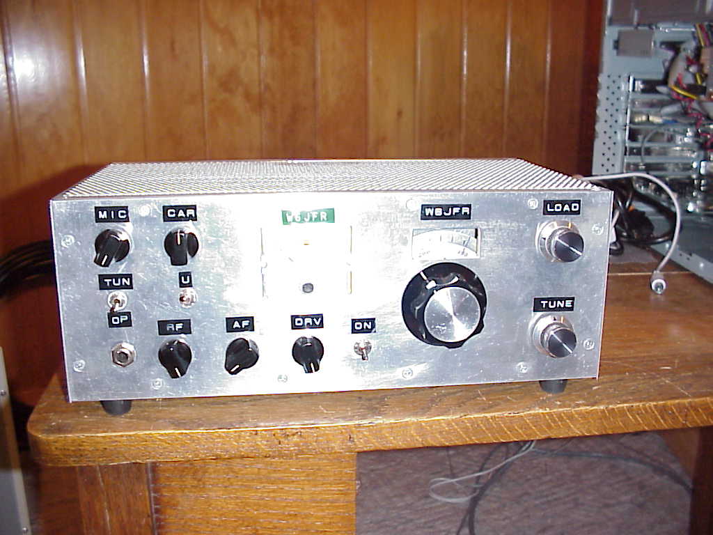
In 1977 I made a decision to scratch build a Swan-120. Only this time I was opting for making it more compact in size. There were to be three modules: a  mainboard, a VFO Module and a driver / final amp module. I built it and the results were less than sterling. One problem was the final amplifier would not be tamed. In disgust I removed all of the parts from the mainboard and just kept the metal chassis plate that was approximately 4.5 X 6 inches. A couple of months ago while looking in a box of old parts I found the chassis plate, which is shown below.
Mind you the size is 4.5 X 6 inches. About a month ago an event occurred that caused me to think about rebuilding that 1977 rig -- with some changes.
The current plan is to rebuild most of the mainboard but to use a solid state audio amp for the output and instead of the tube driver and final to use all solid state devices for about 30 watts output on 40Meters. For the frequency control and BFO frequencies -- yes an Arduino + Si5351. The IF will be at 9.0 MHz using the GQRP Club filter.
Here was the first step and that was to cut some new holes in the chassis plate. Wow there ain't much metal left. I used tube shields on most of the tubes as that will help with the heat dissipation.


The new mainboard with parts installed


First Part Installations

One critical item was the Balanced Modulator transformer which was built from parts from a defunct Drake TR-4 transceiver Balanced Modulator.


Drake's original assembly consisted of a diode ring and two coils. The hardest part of the modification was making the adapter plate (piece of scrap PC Board) to mount the transformer to the chassis. Guys, bragging here, it was done on my manual mill and took all of about 5 minutes, The larger opening is about 3/4 inch square and the two slots were milled out using a 1/16 inch end mill. The Drake enclosure has a forked spring type piece of metal on either end. When fitted into the slot it expands and a couple of tangs on the assembly spring load the fit so once installed it doesn't move.

The modification of the transformer consisted of removing the four diodes and rewiring the two windings to five of the six pins. The Swan transformer had a primary winding that connected at either end to the plates on the 7360. Across this winding were two capacitors in series and the series connection was to ground. Effectively the two series caps make the total capacitance across the transformer the product over the sum of the two. Using my AADE LC meter I measured the inductance of that plate winding and found it to be 35 uHy. Now it is a slug tuned core --so any stray capacitance can be touched up with the slug. Since the BFO is at 9 MHz the capacitance across the winding = 10 PF. Thus two 20 PF caps in series will do the job. NOW I had to do this twice --so keep this in mind --luckily I caught this before applying power. I went into my capacitance storage bin and plunked out two 20 PF caps and installed them across the core and bringing the common connection to one of the pins.

At 3:00 AM my brain awoke me and said "You dummy" those caps have a voltage rating of 50 VDC. Connecting them to the plates of the 7360 that will have 185 VDC supplied to them will blow them up! We are working with Toobs guys think about higher voltages ratings of components!!!!!

With a good deal of arrogance my tribal knowledge is showing as I have built about a half a dozen tube type SSB transceivers and by and large the current technology solid state IC based transceivers are far easier to implement. I have also built some hybrid rigs where the VFO is all solid state and the rest tubes. This one below is basically a  Swan 120 with EL84 tubes in the output for a whopping 20 watts PEP on 20 Meters. I started building this the day I retired in 1997 and it took about a month. The IF is at 9 MHz and used a KVG XF-9B filter. You had to have the knack to build this rig!

Something different than the SW-120 -- the meter reads Cathode Current and was an S Meter as well. Yes this was only possible because of my extensive junk box and having many years of tribal knowledge. Not many hams today can build rigs like this -- but those reading this blog actually could. But first you must start by saying Yes I Can!

73's
Pete N6QW


Thursday, January 18, 2018

2018 ~ The Year of SSB Transceivers

The IC Transceiver Design (Based on K1BQT)

2/15/2018 ~ Thinking out of the Circuit.

One thing I now look at when I am designing a circuit is how can the design be used to better advantage. At times I have been criticized that something I designed was no good for those who like to strap on a back pack, climb up some hill in a god forsaken place and run a QRP marathon. That is never one of my design goals. But of late my goals have taken a twist --how to build things so that circuits could do double duty.
 
This is not out of laziness but time constraints. I have so many projects lined up that unless I look to building less in a project it will be impossible to build more projects. So going back to our 40 (or 20) Meter Driver stage my thoughts drifted toward how this could be used on both transmit as well as receive. Let us start with the basic circuit shown below.


This board is way too large for a compact type back pack rig but was purpose built as I knew I would be adjusting, tinkering and changing things. I often build two versions as the first serves as a prototype and the second becomes the production unit. Often these prototypes have found their way into yet other rigs. In 2016/2017 I built several "Junk Box" rigs out of such leftovers. So initially the thought was this board would be put in the junk box.
 
I jokingly say that I do my best thinking while I am asleep and often my brain awakens me with some sort of an amazing idea --unfortunately it often is at 3:00 AM with my never returning back to sleep.
 
Well it happened again several nights ago specifically with this board. So here is how my brain sent me a message. Suppose we were to introduce some relays on the board so that the signal path could be changed in that the J310's instead of being used as the pre-driver to the 2N2219 was instead "steered" so that is now was the Receiver RF Amp stage, and the Band Pass Filter that followed the J310s' was now steered ahead of the J3110s and what was the output of the BPF that normally fed the 2N2219 was now connected to the antenna circuit. On Transmit the signal path would be restored by the relays to the original design.
 
What we have below is a block diagram of how that would happen. The R & T designations show how the relays would be connected so that the circuit elements could function on either transmit or receive. Now all that extra board space can be fitted with SPDT relays -- four of them. Assuming that an additional RF linear amp stage is added to the 2N2219 (say an IRF510) then you would need to have the 8 element W3NQN filter following the IRF510. So the receive side would have the benefit of both the LPF and the BPF. If one chooses to use just the 2N2219 (at 300 MW) then replace the 5 element LPF with the 8 element and then the LPF could be switched between the BPF and the output of the 2N2219.


My next task would be to add the relays --All Electronics sells these neat SPDT relays for 60 cents a piece. As it turns out the dual filter test board could now be mated with this prototype board and we now will have another transceiver on line. I already know the 2N2219 stage will drive my outboard amp to 30 Watts so I may just skip the IRF510 stage. For those with the backpack stations --lets see you make some contacts at 300 MW.

BTW this also will prove the suitability of buying those filter boards from Israel for $34 delivered to your door. In one of the videos I had of the test setup with the boards spread out on the bench, I received a "negative" comment that it was such a junky mess. Well that may be true but it does work!

73's
Pete N6QW
 

2/08/2018 ~ Time to Drool! The ASUS Tinker Board is Alive and working with Quisk and a Softrock.

For those radio illuminati who lurk the reflectors such as EMRFD and uBitx --let's see yours! The ASUS Tinker Board works with Quisk and is a better alternative to the RPi3.

73's
Pete N6QW


2/5/2018 ~ Some important Updates: Stay Tuned!


Here are the final schematic for the 40 Meter Driver Stage and the plot of the output. Note the 5 element Low Pass Filter in the final schematic. If you were to use this as a standalone output stage I would suggest using the 8 element W3NQN filters to give you confidence that nothing is slipping through. In my designs following the IRF510 stage I have the 8 element filter as the final filter


News Flash ...


Over the weekend my newly purchased Asus TinkerBoard arrived. This board sports a 1.8 GHz Quad Core Processor and  2 GB of onboard RAM. It is better than the RPi3! --  You tube videos and Netflix are amazing. Here is something more ...


Above is the latest Quisk SDR Software which has a built in test signal --look close and you can see the test blip on the screen. This is the year of transceivers at N6QW -- so one more in development.
 
You have to stay tuned for this --it may be a bust; but so far this may be one of the first SDR transceiver implementations using the TinkerBoard. BTW -- I was able to take most of the files that I used when I installed Quisk on a PI2/3 and simply loaded them onto the TinkerBoard. Some of the files required that you use a later version as explained in the latest Quisk documents -- but that went on without a hitch. I guess Linux is Linux.
 
Check my website http://www.n6qw.com and there is a link to the documents used with the Pi2/3. Once again -- N6QWmay be ahead of the curve. See if you can find any info using the TinkerBoard on any of the radio illuminati reflectors? I hope to update the documentation for the TinkerBoard as there are some unique changes that are required. But for now just drool!
 
BTW -- the TinkerBoard is very easy to interface. I plugged in my 5 inch  HDMI Touch Screen and boom it worked. With the Pi3 --there is a lot of hand-hockeying to get it to work. Music playback is very crisp.
 
73's
Pete N6QW

2/2/2018 ~ 40 Meter Driver Board is Finalized!

This morning I soldered up all of the components that would go on the 40 Meter Driver Board including the Low Pass Filter. Success! We are getting close to 10.5 Volts Peak To Peak through the Low Pass Filter measured across a 50 Ohm resistive load. With the driver stage potted I will now start on the main transceiver board. With a bit of effort two Driver stages can be built on a single 4X6 board which likely will be a PC board versus the single sided copper vector board.


More info ... This afternoon I connected the output of this driver stage to my commercial amp which is a Communication Concepts Inc. AN762 --good for almost 150 watts output. With just the drive coming out of the 2N2219 --I was hitting over 30 Watts PEP. So this combo is now on par with the amp that was originally designed for the K1BQT project. I could even envision this small driver stage with one of the $15 amp kits being sold on eBay that are good for about 45 watts.

A new day has dawned and for very little $$$$ invested you can have a rig that is good for making lots of contacts.
 
73's
Pete N6QW


1/30/2018 ~ 20 Meter Driver Final Stage Data.

Yesterday I posted the 40 Meter results and this morning using LT Spice I simulated what would be needed for the 20 Meter version. There are three circuit changes including the transformer on the output. Since we are bit higher in frequency the FT-37-43 had a few hiccups and burps to get it to peak on 20 Meters. That is when I went to the FT-50-61 core and with 16 Bifilar Turns put it smack on 20 Meters. I also changed the in/out coupling caps to 10 NF (0.01 uf). Having the Band Pass Filter ahead of this will insure just the 20 Meter energy is getting to the stage. This would then be followed by the 20 Meter Low Pass Filter. This could be a breakthrough module used in many driver applications.

73's
Pete N6QW


1/29/2018 ~ A Breakthrough -Driver Finalized!

I attempted to use the BS170 as the final stage -- and while it looked good on paper it flunked the smell test. So I shifted gears and went to a conventional BJT to do the heavy lifting and we were successful! Boom this stage is potted.


While the sketch shows 12 Turns on the BFT --use 13 turns as that value produced the following plot from the LT Spice simulation

Notes on the schematic the center wiper on the 200 Ohm trim pot is connected to the 100 NF cap and the settings are proximate. Look at the output on a scope and find the setting for the best linearity. The Resistor R7 is a 200 Ohm trim pot connected as a variable resistor is in parallel with a 100 ohm resistor. These two trim pots give a coarse and fine setting of the output. Tune for max smoke and best linearity.

Finally we have a video. Even I am impressed at what we now have for the IC Transceiver. With the 20 Meter Driver we will need to put less turns on the FT-3743 Core. I will determine that value and post it on the blog.


I plan on building the LPF and will rerun the tests --but for now we have moved the needle.

73's
Pete N6QW

1/28/2018 ~ Adding the Band Pass Filter.

I built the filter and it wouldn't tune up and the pattern looked like crap. I thought maybe a bad capacitor --but that wasn't the case. The problem was on boot up the Arduino was set for 20 Meters and the screen was not facing me. Then I had an Ahh Ha moment --the filter is on 40 Meters. A quick change of frequency in shirt order showed it was a solid design -- And I get out about 3 Volts Peak to Peak. That should be a good place to start when I finish off the BS170 stage.
 
73's
Pete N6QW


1/27/2018 ~ Pete's Build of the Driver Stage.


Today I started work building the 40M version of the driver stage. This is a prototype build and thus quite large real estate wise. Ultimately this circuit will be built on the single sided copper vector board. I often build two or three prototypes before we "freeze" the design. Of these prototypes end up in new transceivers.

I just finished the first part of the build which is the substitute circuit for the 40673. I am very encouraged! The power out just from this stage was 10 Milliwatts. Follow on work will involve the Band Pass Filter. the BS170 RF Amp stage and then the 40M Low Pass Filter. Watch the video.


This is starting to get exciting.
 
73's
Pete, N6QW
 

1/26/2018 ~ IC Transceiver Builders Report.

Nick, G8INE has done several things to take on this project. First he purchased a table top CNC Engraving/Milling Machine. Unlike me it did not cost him $250K. He is using one of the machines that can be had in the $200 to $300 range. Next he taught himself CAD and designed a SMD board for the IC Transceiver Driver stage. Finally he cut a board and wired it up (should say no wiring involved). The board will shortly undergo testing to verify the performance as indicated in the LT Spice Simulations. Here is Nick's handiwork.
 
 
Kudos to Nick and his board. We will report on his test results. Nick did comment to me that once he had a board that it was a lot easier to build the module. Now the icing on the cake --when he goes to build a second board he simply chucks up a piece of PCB stock, calls up the program and punches the start button. That easy!
 
I was a bit waylaid on building my board as my time was spent on the SBE-33 whose transmit signal sounded like crap. This prompted replacing all of the electrolytic caps in the HV power supply and the microphone amplifier stages. I suspected the rather unusual voltage regulation circuit may need a rebuild too. I did make one on the air contact and there was a report of FM'ing on voice peaks. That is a well known problem traced to impacts of voltage regulation on VFO circuits. Now if there was a Si5351 in there we would not be talking about that subject.
 
Thanks again Nick for sharing your efforts.
 
73's
Pete N6QW

1/24/2018 ~ More Trips back in Time. The SBE-33.


Final fixes included opening the TR relay case and added a drop of De-Oxit to each of the contacts. Tribal Knowledge use the end of a wooden toothpick to apply a small drop to each contact. I also (using the low setting) applied a bit of De-Oxit spray into the Volume Control and Microphone Control. SBE recommends a dynamic microphone or a powered crystal microphone but avoid a pure crystal microphone. Note an Electret Microphone will not work with this directly --no bias at the microphone jack. I hope the OBTE have taken notes with their latest Iphone.
 
 
I hope to check into the Vintage Sideband Net tomorrow evening.
 
73's
Pete N6QW

1/23/2018 ~ Inconclusive Results. Trial By Test.

I tried several simulations and the results were not what I reasonably thought they should be. First I changed the resistor from Gate #1 to Ground to 10K Ohms just as in the original design without changing the turns ratio on the Input matching transformer. Boom the output jumped another 5dB to something in excess of 30 dB for the 40 Meter version. Most of the heavy lifting is in the final stage with something close to 25 dB just in that stage. Without changing the turns ratio that 10K would look like 225 Ohms at the primary. So that certainly left a big question mark.
 
Several other configurations were evaluated that step down the 10K impedance using various simulations. A simple 10 Bifilar turn FT-37-43 was connected "step down" was tried. Using the bifilar approach results in a 4:1 --so I could make 10K look like 2.5K which then would mean changing the Gate resistor to a 2.5K Ohms and this would replace the matching transformer. That configuration resulted in less gain. So we are back now to testing configurations with real hardware and evaluate which one works best.
 
One option would be for the final configuration would be to "build per print" with the 10K resistor on Gate #1 as T1 does give a 4:1 so that the third winding results in a 10K value.
 
However to evaluate the amplifier block with actual hardware and a BS170, I will use the 2.2K Ohm with the matching transformer first specified as I will be driving this stage during the test and evaluation from an ADE-1 which has a Zout of 50 Ohms. I have the board cut so now I need to start adding parts. The evaluation essentially has two components --1) does the circuit work as an amplifier and the gain developed and 2) what works the best when connected to U7.
 
73's
Pete N6QW


1/22/2018 ~ Not so Fast Batman --The Batmobile may have a problem!

For many years now it has been obvious that while asleep my brain keeps churning away thinking about problems/issues/concerns with designs I am working on at that time. It is both a blessing and a curse. A blessing because I may find a problem before it raises its head as a problem. The curse part is that it is usually around 3:00 AM and I am awakened --never to get back to sleep. It happened last night.
 
Sometimes when we chunk a project into modules --we miss something at the interface. This might be the case with the K1BQT original design. Below are two parts of the original schematics. Take a minute to look these over. Read on.


T4 on the output side of U7 is a trifilar wound transformer consisting of 9 Turns X 3. Thus two of the windings are connected bifilar fashion which essentially puts two of the windings in SERIES for a total of 18 Turns. The third winding, the output is stand alone with one end grounded and the other end that ends up on Gate #1 of the 40673 which has a 10K resistor to ground.
 
So we have an impedance transformation from the output of the MC1496 to the input of the 40673. So lets look at that transformation in light of turns ratio squared. Thus 18^2 = 324 and 9^2 = 81. We have a classic 4:1 transformation (For the OBTE 324/81 = 4). So the output impedance looks like 1/4 the value in terms of the input to the 40673.
 
You might want to Google Maximum Power Transfer Theory in relation to impedance matching. You get max juice when the impedances are matched. So now the Question would be what is the Output Impedance of the output of the MC1496 and what does the input impedance look like for the 40673. Not withstanding the actual values --there is a 4:1 transformation taking place. So we need to go down that bunny slope to assure there was matching taking place as that impacts what we do in the redesign.
 
In the Simplecever Plus Project I addressed this issue by forcing the input of the J310s' DGM to be 2.2 K Ohms and then did a match from 50 Ohms to 2.2K Ohms with a 3 Turn to 20 Turn Broad Band Transformer. Thus 3^2 = 9 and 20^2 = 400 resulting in 400/9 = 44.4. Now if you take 2200/50 = 44 --close enough. Thus 50 Ohms at any output will look like 2200 Ohms at the Input of the DGM.
 
Below is an example of how this matching was done on the Simpleceiver IF stage. The 1st match was 3 to 20 turns and the 2nd out of the crystal filter was 170 Ohms to 2200 Ohms thus a slightly different turns ratio but always presenting 2200 Ohms to the input
 
I have now modified the two driver amps to include input matching from 50 Ohms to 2200 Ohms
 
Some tribal knowledge here -- if you simulate these in LT Spice and add the inductor mutual inductance notes (K9 L8 L9 1) be certain that when you make that note to check the dot that says invoke Spice Command --otherwise you will get no output.
 
These changes added about 10 DB to the output. Now lets see if we can track down the output Z of the MC1496. Maybe K1BQT accounted for this in the Out/In impedances but given I am changing his design I want to make sure I have accounted for the matching.
 
You can scroll down this posting and look at the original plots. Matching is important!
 
When I get the output impedance of the MC1496 we can modify Transformer T4 on the schematic (if necessary) so that its output winding is 50 Ohms. Now we could be really clever and once we know the output impedance we could use a single transformer so that the primary Zout matches the Secondary Zin to 2200 Ohms. I prefer two transformers but it could be done with one.


So let us now check the MC1496 Data Sheet that can be found here. The Output Resistance for the Parallel Outputs is 40K Ohms. So if we look at K1BQT's transform it is 4:1 and thus 40K looks like 10K into the base of the 40673. Thus the design as presented is absolutely correct. K1BQT was spot on!

Now how do we match that into my 2.2K Ohms?

Well lets us start by looking at T4 so we would have a 40K to 50 Ohm match which is 800:1 and with only 18 turns on T4's Primary -- you would end up with less than a half turn on the secondary --that won't work. So now lets look at the transformer on the input of the J310s and what can be done with the primary side. A 10K to 2.2K transformation is a 4.55:1. So now if we modify my input transformer to have a 15 turn Primary and 7 turn secondary we have the following: 15^2 = 225 and 7^2 =49. 225/49 = 4.59:1 is close enough. So I will run some plots with this transformer.

Now alternatively we could change the input to 10K and see how those plots look with a source of 10K pumping RF into Gate #1 with a 10K resistor to ground.

This exercise has served the purpose of looking at impedance matching and how to adjust input / output impedance matching.

Stay tuned tomorrow for the plot data with the new input transformers.
 

73's
Pete N6QW

1/20/2018 ~ Prototype board layout for the Driver.

I will start the build of the first prototype Driver stage. My process begins with using G Simple to lay out island squares and the cut it on my CNC. The layout facilitates parts changing, circuit changes and lots of measurements. Once I get a working circuit I will convert this to the single sided copper board which will be another prototype. Finally I will build two "production units" for 20 and 40 Meters. I have left space on the board to add shields should that be necessary. If one desires this could be done over a sheet of copper PCB using Rex's W1REX MePads.  For reference purposes the CNC will cut this board using a single piece of 4X6 board and pretty much fills the board.


That is the beauty of having a CNC Mill. Five minutes after I finished the design I had a board in my hand.

CNC Engraving/Router Mills can be had for about $200 to $300 on eBay. So within reach of many homebrewer enthusiasts. This  board is way larger than needed but since it is a prototype we will be doing lots of "peaking" "tweaking" and adjusting and thus the extra room


Stay Tuned.

73's
Pete N6QW

1/19/2018 ~ Cleaned up Schematics for the 20 & 40 Meter Driver Assemblies.

I took some time to clean things up on the schematics so that the components were more readable and to include any coil winding data. The plots previously presented are essentially the same.


The 40 Meter version has slightly more gain but the minimum gain is 5 DB in both cases. Note that "R" on the schematic is a combination of a 10K trim Pot (Drive Control) where the top end is connected to the bottom end of the 22K resistor, the Center Wiper connected to gate #2 and the other end is connected to a 2.2K resistor which has its other end grounded.
 
K1BQT has a ferrite bead connected to the lead on Gate #2. Since my trim pots are board mounted I have not found this necessary. That said should you panel mount a pot then more care in lead routing and a ferrite bead may be required.
 
Caveat Emptor -- These circuits were simulated in LT Spice and not actually built which will be the next step. However, The J310's stage and the Band Pass Filters have been built and used in other rigs so these parts are known quantities. The substitution of the BS170 for the 2N7002 and the simple Low Pass Filters are new and thus will be evaluated. Should these two circuits work well then they will become a standard module that could be used in any rig design. I am hopeful this is the case.
 
I would encourage those with more sophisticated test gear than I have to build one of the circuits and run a Spectrum Analysis and share with us what you find.
 
One more thing: I used T-68-2 Red Cores for the 14 MHz networks. I invite your attention to the information in the chart below provided courtesy of Amidon.  Red Cores are OK at 14 MHz.  The Q's are good enough with the T-68-2 cores (Al = 57) . But if your shorts are all wadded up, then with the inductance values provided you can calculate the turns required for the type 6 (yellow) cores for the 14MHz networks. Al value for yellow T-68-6 cores = 47. 


Stay tuned -- this is the year of SSB Transceivers!!!
 
73's
Pete, N6QW
 
 
*******************************************************************************

1/18/2018

We have earlier presented the reference document for this project and in looking over what will be kept pretty much intact versus design anew, the first piece to be designed is the driver stage following the IC lower level stages.
 
The basic LM1496/MC1350 pieces will literally go untouched. That said the driver, final RF amp and Audio Amp stages will likely get a going over. My initial thoughts were for a two band rig that will be switched by a simple DPDT toggle switch. This starting point affected what I did with the driver stage.
 
From K1BQT's design the driver stage looked like this:


In 1985 this was state of the art and we will build on the idea of a Dual Gate MOSFET driving a N Channel Enhancement Mode FET. Since 40673's are not like a stock item I will build one using two J310's. This is a proven approach and works perfectly! The IRFD1Z3 is like un-obtanium and so we'll substitute a BS170.  Touring Rick's design the 40673 can have an adjustable "Drive" level. We will do likewise with the J310s. The 40673 was followed by a Band Pass Filter and then to the IRFD1Z3 with a Low Pass Filter on the output. K1BQT was very careful to state that if you use bands other than 75 Meters you will need additional filtering.
 
So if we use just the J310's and the BS170 as a single amp we would have to be able to switch the Band Pass and Low Pass Filters which adds a lot of diode and/or relay switching.
So what if we built two complete separate driver assemblies and then it would only involve a SPDT relay at each end of an  Assembly to switch between the Assemblies and then a third SDPT relay to provide power to the Assembly being used. This approach does several things for us including making the switching a bit less complicated but more importantly each driver assembly can be optimized for the band being used. The added cost would be for a couple of devices (2X J310 and 1 X BS170) and a few resistors, caps and ferrite cores.


Today I took a crack at designing or should say simulating two separate Driver Assemblies. Should mention that the Dual Gate MOSFET Stage is a stock design that I have used in several rigs as is the Band Pass Filters. What has not been previously tested is the BS170. So after presenting this design I will build a prototype and run some tests. the simulated plot as a starting point shows great promise. 


Take a hard look at the schematic and note that the Band Pass Filter is terminated at each end with 50 Ohms. If you want a rude awakening remove the input side 50 Ohm resistor and run the plot. Do not remove this resistor.


Again these are the first pass and I will build a prototype to insure they works as deigned.

Stay tuned and start ordering the parts.

73's
Pete N6QW


The Risk of Power.

 What happens when the faithful lose faith? We don't know the result but now it is time to pop more popcorn as the interesting part of t...