Saturday, April 14, 2018

2018 ~ The Year of SSB Transceivers

5/6/2018 ~ Update


I Love the Smell Of Napalm in the Morning!

That specific line came from the actor Robert Duvall in the movie "Apocalypse Now" but is reminiscent of May 7, 1965 when as a member of MCB 10 [Mobile Construction Battalion Ten ~ SeaBees] and part of Regimental Landing Team #4, we made the very first amphibious landing since the Korean War. 

The landing zone was at Chu Lai, [at then South Vietnam]  some 90 "clicks" south of DaNang. Several months later (July 1965) I remember sitting on the veranda of the "homebrew" officer's club where at about 6 to 7 PM we would, with drink in hand, watch the nightly napalm run south of us on  Dung Quat Bay. Our camp (originally called Camp Shields) is now the site of a KIA plant as a part of the Chu Lai Open Economic Zone. My how times change? The 10K foot long  airfield that was built by RMK is now known as Chu Lai International Airport
Here are some photos that have survived ....


Lt. (jg) Peter G. Juliano CEC, USN Chu Lai 1965

Yes guys that is me about 53 years ago --also note I was  a "regular" and seriously contemplated a career in the US Navy. Two trips to Vietnam convinced me that was probably not a good idea. Note the "squared away" US Marine style hat. I even spit polished my combat boots. The gig line was straight and the blouse was "dressed". Noteworthy I was picked up 'early for full promotion to Lt. CEC USN. 


The above photo is the "Officers" shower facility and the man near the right hand center of the photo is taking a "whiz" into an outdoor urinal. This device invented by the Seabees is comprised a 12 inch diameter piece of PVC pip sunk into the sand and that is it. I must admit that after a few drinks the 12" target was hard to hit and the same problem late at night.

The next photo taken in 1965 should conjure up thoughts of the movie and TV series "MASH" -- I think the movie stole our lifestyle. That is my rack in the corner of the hut. Please note that my 782 Gear is packed and at the ready. Oh there are those asking what is 782 gear. Well the Seabees worked closely with the US Marines and adopted many of their processes and procedures. The term 782 refers to the form used to delineate the field gear that a US Marine (or Seabee) is issued. Typically this is a pack, helmet, entrenching tool etc --you know 782 gear.


Pete's rack and living space in 1965. I used to sleep with my 45 under my pillow. Funny story about that as in December 1965 I was selected to be the OIC of the advanced party for rotation back to the states. Because our battalion had been dramatically augmented by about 20% the day before I left I was asked to turn in my weapon as they were short of guns!

That very night our camp was attacked by the Viet Cong and we actually had VC inside the camp --and here I was without my issued weapon. At that time the sort of loose rules were you could have a personal side arm and I did have a .357 magnum which luckily was handy. Here I thought I was about to go home it might have been in an aluminum box. It was scary. I sort of wished I had a grease gun as a few of the guys did have those.

I do have to mention that our most significant piece of communication gear was a Collins AN/PRC-47. Which only went to 12 MHz and USB and CW. But I did manage to get some listening time in the radio shack and thought how cool it would be to operate from south Vietnam. We did have a Collins ham station KWM-2 30L1 but because it was so early in the war --prior to our getting there the total US forces were only about 10,000. That May it jumped to 20K so MARS and other stations were just getting approved. 

Too bad some our government leaders never spent time on the front lines. But we all know that story.

73's
Pete N6QW


Improving the Prototype #1 4/29/2018!


Starting by doing some analysis I looked at two possible factors that would improve the low frequency transmitted audio response and we have two significant players among many.

1. First is the Filter Bandwidth. I am now using a Ladder Filter where all the Capacitors are the same. Initially that was not the configuration. The values of the five capacitors play an important role in the bandwidth as lower values make the BW wider and higher values make it more narrow. For the reworked filter the values of all five caps in 68 PF. I did find that this change opened up the bandwidth and that is obvious in tuning across signals. Further evaluation may find that some sort of happy medium may be in the 75 to 82 PF range.

The filter changes make obvious better/worse conditions on the receive end --- but there are other factors that affect the transmit side including the filter.After making several contacts it was found that the signal reports were quite good with excellent characteristics in the mid to high range (a DX machine) but still a little low in the lows. This lead us to the other player in this game

2. The second factor is the response of the audio amplifier stage, which in this case is a single 2N3904 -- a bare bones stage. This is where having LT Spice at your fingertips is a critical tool. BTW just got it re-installed on my new computer after struggling to get the new libraries for the JFET's to work which now includes the J310. 

So here is some data for you. I have reason to believe the first prototype has this stage installed.


In looking at the plot data we can see there is about a 6 dB variance in the signal level at 300 Hz below what you see at 1.2 KHz. So that is why perhaps we are seeing the lack of lows.

Now if we diddle with several of the capacitors we get the following plot. Now the signal level is flat from 300 to 3kHz. Much better!


The revised schematic involves changing 3 Capacitors.

I will physically make those capacitors changes and report the results. LT Spice is an amazing tool and a few minutes with the computer let's you fix things.

Get cracking -- time to build this rig.

73's

Pete N6QW


Another Transceiver on the Boards 4/25/18

Yes it is on the boards -- breadboards.


Often you hear me talk about building several versions of transceivers with the 2nd version having the value of the "learning and improvements" from the first version that is incorporated in the later version . You see that later on in this post with the Shirt Pocket Transceiver.

One of the most successful projects I have undertaken was the Simpleceiver Plus which was completed in late 2017. That was version two and the version one prototype was simply put on the shelf. One of the main differences between versions was the crystal filter and the filter frequency. Version One was a four pole homebrew filter at 12.096 MHz and Version Two was a commercial 9 MHz six pole filter. Most of the other circuitry was the same with the exception of an SBL-1 used in V1 for the Rx/Tx mixer and in V2 it was an ADE-1. 

Critical to the success of this project was the use of J310's configured as a Dual Gate MOSFET. I also used extensive relay switching of the signal path proven with V1 so that in the final form there are essentially three Dual Gate MOSFETs that are the heart of the project. One J310 DGM serves as the receiver RF Amplifier while also serving as the Transmit Pre-Driver. A Pair of J310 DGM's act as amplifiers ahead and following the crystal filter. Relay switching essentially uses a single pass system so that on receive the signals coming out of the Mixer stage pass through the amplifier block onto the Product Detector. On transmit the Product Detector is now the Balanced Modulator and its output is relay switched to the input of the first IF amp. The output of the second IF amp is directed to the Mixer stage and then on to the former Rx RF amp which is now the Transmit Pre-driver. The signal is now switched to transmit RF amp stages.  LOTS more relays but lots less circuits. 


Two days ago, while looking for something entirely different, I spotted V1 sitting on a shelf, looking somewhat forlorn as I had robbed a few parts from the transmit linear amp stage; but otherwise unmolested. Given this was such a critical development tool for the later project, it was time to make it whole again.

About 10 minutes worth of work involved with liberating some boards from yet another project and the Version One was back on the air. A few on the air contacts with some of the Flex6700 ops indicated that the signal sounded OK but seemed a bit narrow lacking the lows they like to hear. There were no comments about distortion or burbles or spurs just that it sounded narrow. The further comment --it would be a great signal for busting pileups but for the "40 Meter Illuminati " a bit narrow. 

I looked at the coupling caps that were originally used in the homebrew filter and concluded that the filter would indeed be some what more narrow than the 2.8 KHz the Flex guys like to hear. My calculations indicated about 2 KHz bandwidth. So about 10 minutes of additional work and some new caps resulted in a  a newly refined homebrew filter. I can tell the received bandwidth is much wider .

Last night about 8 PM local left coast time --the 40M band was wide open and I made about a half dozen quickie contacts --some sort of contest. Half of these contacts were with east coast stations including one right in the heart of PA District 8-- Connor Lamb country. BUT there were a  few unsolicited reports -- like "you have a great sounding signal." So those are some data points; but we need more rigorous data collection before declaring victory. That I hope to do today. BTW --no QRP during the operation last night --was running 600 Watts. For those who wonder -- no beam just a droopy dipole with an apex at 25 feet. 

Using the SEARCH function on this blog type in simpleceiver for the many details of the build.

Some Photos of the "Al Fresco" build: [Yes that is a breadboard C Clamped to the work bench.]

The Rig 

The Display


EMRFD Driver and IRF510 Final

The Mess ~ But it works so well!
There is a total of 8 boards and with a bit of effort can be made a lot more compact. That is the plan. Get crackin -- you can build this rig.

73's
Pete N6QW

N6QW Innovative Transceiver Projects!

One of my goals for 2018 is to share information about my past projects in hopes that other homebrew enthusiasts will take up the iron and "roll their own" Many of the projects go back over ten years; but are relevant today.

You can make great contacts using homebrew gear! But I should caution you that you may get comments from the other end such as "well I am looking at your signal with my FlexRadio 6700 on a 72 inch screen and it appears you are 10 Hertz low in frequency". You gotta have thick skin--just think your rig cost $100 and his maybe $10,000. But even being 10 Hertz low --you are still having a QSO. 

There are three specific projects I would like to cover today and these include the following:

The first is a 20 Meter SSB transceiver that used MMIC's (Monolithic Microwave Integrated Circuits) arranged in a bilateral configuration. There were six total MMIC's employed in three sets of two for the bilateral amplifiers. This was kind of leading edge in 2011 for a homebrew ham transceiver. Initially I used a VTO (varactor tuned oscillator) but later this was changed to a Si570 VFO via a K5BCQ kit. [This was another rig given away when I had to move in 2013.] This by my definition an innovation in a ham rig.]

The second rig is a 17 Meter SSB Transceiver originally built in 2007. The innovation here was to use a crystal switched Super VXO to give a wide frequency coverage. The innovation here was the selection of the IF 4.9152 MHz and using 11.52 MHz crystals in a diode frequency doubling Super VXO circuit produced a signal; a 23.04 MHz and in doing the math 23.04 - 4.9152 = 18.124 MHz. Using the doubling circuit gave twice the swing in a Super VXO circuit. That worked so well that I custom ordered additional 11 MHz crystals so that I can cover almost the whole 17 Meter phone band.

The third project was a Shirt Pocket Sized 20M SSB Transceiver which was built in two versions with the first requiring a rather large pocket. The second version is 2X2X4 inches --still needing a big pocket. A third version planned for 2018 is to be Altoids tin sized. This rig also employed a 4.9152 MHz IF and this time a crystal switched heterodyne VXO. The first version in 2017 was retrofitted with a Si5351 and OLED Display.


Some Project Details:

The first is the MMIC Transceiver which was the very first "big time" article I ever wrote about one of my projects --this even made the cover of QRP Quarterly. The embedded you tube video was made at the time the rig first had the VTO and the drift is pretty apparent. It was real crap. The final version with the K5BCQ Si570 VFO kit --was like night and day. I regret having to give this rig away when I moved. In 2017 I used the bilateral MMIC stage in a compact 20 Meter SSB transceiver. The AG-303-86G is a superb device. As I mentioned in the article I got help with the bilateral circuit from a ham at Tri-Quint who was the manufacturer of the MMIC.

In passing at times you bump into things that amaze you. A friend sent me an eBay listing for the AG-303-86G MMIC device from a seller in Israel. In the ad, my schematic for the bilateral stage was featured to show how they could be built into the circuit. The MMIC's are termination insensitive good from DC to 6 GHZ and feature 20 dB gain. Should mention that the data sheet includes the required resistors for various sources voltages which enable you to run the devices on anywhere from 5 to (I think ) 9 VDC. I picked  5VDC. Another neat feature of my circuit is diode steering so that when you "bias on" the MMIC that also steers the signal right left or left right. So OK another bit of innovation --for 2010.

To the best of my knowledge I am unaware of any other homebrew rig which used MMIC's in a bilateral configuration in 2010. I am sure there are commercial designs but my application may have been a first. I am sure blog readers will let me know otherwise.

In the last photo is shown the MMIC board (underneath the green perforated board) and a shot of the completed rig. There are two stories here (actually three) with first being the suitability of the MMIC's for our beloved rigs. The second is that the MMIC's can be effectively used in a bilateral configuration and the third -- great for making compact rigs.


The 17 Meter SSB Transceiver Project:


The second project is a 17 Meter SSB Transceiver first started in 2007 where some fundamental circuit blocks were initially developed that found their way into future projects. The heart of this rig was a bilateral amplifier circuit developed by G4GXO [SPRAT # 128] which used either a Dual Gate MOSFET or two J310's configured as a DGM.

Based on some information gathering in preparation for the build, I discovered that in the Elecraft K2 the IF Frequency was 4.9152 MHz. Hmmm good enough for Elecraft so good enough for me. This was a wise choice as I soon discovered that using a stock computer crystal of 11.52 MHz in a diode frequency doubling VXO circuit produced an output at 23.04 MHz. The frequency scheme in a down mix resulted in tuning smack in the middle of the 17 Meter Phone band. Subsequently I purchased special frequency commercial crystals that provided the upper phone band coverage of 17 Meters. A trick I used was to switch the VXO crystal banks was a relay that was controlled by a panel mounted toggle switch. Thus I had a high range of VXO frequencies and also a low range. The yellow cube in the photo below is a DPDT 12 VDC DIP Relay. Because of the frequency doubling two crystals per range in the Super VXO Circuit provided a large frequency excursion.  

Also note the use of single sided copper vector board where a solid ground plane is the norm. After using this (somewhat expensive) medium you never think of Manhattan construction for projects like this. All wiring is point to point underneath the board. With some circuit noodling of the layout it is possible to achieve a layout that minimizes the circuit wiring and reduces the possibility of unwanted coupling. Some nice innovations here.


Complete details of this transceiver can be found on my 2nd Website Believe it or not this project started out as an attempt to build a shirt pocket SSB transceiver which resulted in a working rig; but definitely not something to fit in your shirt pocket. The boards above were finally fitted into an aluminum chassis measuring 7X7X2. There is room in that chassis to fit an Arduino/Si5351 and an OLED Display. That is in the queue.


The 20 Meter Shirt Pocket Transceiver:

As I stated earlier my initial quest to build a shirt pocket SSB transceiver started in 2007; but it was not until 2011 that I arrived at a shirt pocket sized transceiver. A rig 16 cubic inches is small BUT you still needed a large shirt pocket --Paul Bunyan sized more like it. In 2018 I am looking forward to building this same rig into an Altoids sized tin. 

In 2011 I was overtaken by the desire to really get serious about a shirt pocket sized transceiver. W3TLN, Ed Vester built an all solid state SSB rig running 100 Milliwatts on 20 Meters that ran off of 6 VDC. The choice of 6 VDC was because it was a mobile rig fitted into a Volkswagen Beetle -- an early version with a 6 volt battery. It was a small rig and used a homebrew crystal filter and a VXO. The Vester rig was published in a QST article and subsequently published in the ARRL Sideband Handbook. 

I built the Vester rig in the 1970's from the ARRL Sideband Handbook. But I could never get it to work. In the course of preparing some articles for QRP Quarterly, in 2010 I mentioned to John W5DIA about my non-success with the earlier project and he sent me a photo copy of one of the pages in the original article. BOOM --the article and the Handbook version schematics were different. That was my problem! I had a difficult time reconciling how there could be two different versions of the same schematic --in a QST publication...


Thus having found the problem with the Vester rig I decided that I would just build my own version -- the Vester rig was 7x7X2 --not a shirt pocket rig.

I built two versions of the shirt pocket rig with the idea that the first version would be the proof of concept and the second would capitalize on that experience to make it really small.

The is information on my  website  http://www.jessystems.com/20MSHIRTPOCKET.html about this project including some schematic diagrams. This project also was a subject of a QRP Quarterly article. 

Noteworthy the original rig used the same crystal switched VXO approach as in the 17 Meter Rig  with a twist in that the Super VXO operated at 12.906 MHz and was mixed with crystals in the 6 MHz range to give about a 120 kHz spread on 20 Meters. The reason for this choice/approach was the availability of standard computer crystals.


Fast forward to 2017 and these rigs have been further modified with new case colors and Version 1 and been retrofitted with a an OLED/Si5351 and Nano digital LO.


This is a lot to absorb ... but is provided to open up a view of the homebrew possibilities. It goes without saying -- most of these are not first time projects but they do offer an insight into the amazing (and cheap) technology that is available to us today.

73's
Pete N6QW

Sunday, April 8, 2018

2018 ~ The Year of SSB Transceivers

Building the W7ZOI, 20M SSB Transceiver

4/10/28 ~ Comment: this rig is only one of three that I have built that is fully SSB and CW capable. with the other two being the KWM-4 and this rig's twin brother. Unless you provide capability for narrow signal filtering then operating CW using a wide SSB filter (700 Hz as compared to 2.1 KHz) does not make for a competition grade rig. OK for casual contacts; but not one for a true CW enthusiast. Today I would look at a diode steered two filter scheme and like in the KWM-4 and the W7ZOI rigs use a separate CW keyed crystal oscillator (or the third clock on the Si5351). 

Since I am not a CW enthusiast nor always QRP my main thrust is SSB and to have linear amps on the output. Hats off to those who like QRP + CW. There is room in the hobby for all.

73's
Pete N6QW


In 1999, I decided to build the W7ZOI 20M QRP SSB Transceiver that appeared in a two part article 12/89- 1/90 in QST. [That was before contests and latest product reviews consumed so many pages of the publication.] The wait to build the rig was that I was put off by the use of an analog VFO with its attendant drift and finicky tuning. By 1999 I had learned to use the VFO stabilizers and thus the time seemed right.

From a nostalgia standpoint the VFO, built inside a 1/4 inch plate aluminum box was originally used with my 1970's LM-373 transceiver that was rebuilt in 2017. I just can't seem to throw stuff away!

This build was large and had many circuit boards. A second identical unit was built and has a much smaller footprint. Recently I have taken to stealing parts from the 2nd rig but now I think I will rebuild that rig with a Si5351 versus the analog VFO with the VFO stabilizer. Yes you guessed it the very 1st thing I liberated for the uBitx project was the cool blue display.


This series of blog posts has convinced me that I have OCD about building transceivers and should entertain professional therapy. ... Just one more rig ...

73's
Pete N6QW

Monday, April 2, 2018

2018 ~ The year of SSB Transceivers


The KWM-4 ~ A True Homebrew Rig.

Pete N6QW

Who is Doing What to What?

(No this is not about the Emperor and the Porn Star!)


I raise this question because I think it is a good idea to always look beyond what one is doing in their shack and to see what is over the fence. I am on a quest to build a complete 20M homebrew SSB transceiver within the confines of an Altoids tin. The last time I built a really small SSB rig it was 16 cubic inches (2X2X4). So now how to make it even smaller.

To that end I am firm believer to doing research on what others are doing, which lead me to K.P.S.Kang, VU2KR. He has a blog called http://smallwonderqrp.blogspot.com 

In the May, June and July of 2016 blogs there are entries regarding a rig he designed called the PIXET. This is an amazing design and it has many possibilities "built as is" as well as looking at the topology and how that could be incorporated into my "super small shirt pocket transceiver". Keep in mind there are always better mousetraps!

My friend Bill, N2CQR will love the PIXET, as it is an HDR (hardware defined radio) with loads of 2N2222's. The four pole filter is at 4.4333 MHz and the design seems straight forward. It also has plenty of get up and go with a pair of IRF510's operating with 24 VDC on the drains -- this is probably easily good to 20 Watts. The IF is a good choice and avoids some of the problems encountered at higher IF's.

At the heart of my quest is 1 watt on 20M and small size. My last small rig used about 95% of leaded components -- this time it will be mostly surface mount. Aside from the power level and small size this is to be a real rig and something fully usable and not in the toy category -- a real rig. The display will look like this and the controller will be a Pro Mini.


Yes, Virginia that is a quarter dollar in the photo --so you definitely see where this is headed.

Stay tuned.

73's
Pete N6QW

Sunday, March 25, 2018

2018 ~ Year of SSB Transceivers

Exploring Upgrades and Improvements!


"JABOM"

3/30/2018


Hey guys (and gals) great news: The JABOM is cranking right along. Yesterday on a band that seemed virtually dead (and using the linear amp @ 600 watts out) I worked Portugal in mid-afternoon. The signal reports are excellent and I couldn't be more pleased. It is a testament to the design and circuit topology. The you tube  video documents the receive performance. The on air contacts demonstrate the transmit performance. 

While not having all the bells and whistles of commercial rigs the JABOM demonstrates that solid contacts, including DX contacts can be made using homebrew equipment. You only to get off the couch and now that March Madness is over --heat up that iron.

73's
Pete N6QW


3/28/2018


*********************************************************************************


3/26/2018 ~ More work on the front Panel.


The Before C Change:

Changed on 3/25 to a really super large LCD Display ~ No Squinting here!

The After C Change:


That is the advantage of having a CNC Mill -- you can make Escutcheons that hide some of the ugly former installations. The material is a piece of single sided copper PC Board and the plan is to paint it black. 


I received a letter of chastisement regarding what is on the display. The top line shows 14.200.000 MHz which has been pointed out to me is incorrect as it really is by convention the following 14.200.000 Hz. It would only be correct if it read 14.200 000 MHz which results if you remove the second decimal point. The person so notifying me stated the second line was correct. So my next iteration of the code will remove the MHz and in its place will be either USB or LSB. The bottom line will be changed to include my call sign.

You have to admit --this has a lot of drool factor!

73's
Pete N6QW
*********************************************************************************************************


One of my most successful projects was what I affectionately called JABOM which was the subject of an Article in QRP Quarterly. JABOM was an acronym for Just A Bunch Of Modules. At the time it was built the rig transitioned from a varactor tuned VXO, to one with a variable capacitor VFO to finally  to digital VFO sold as a kit from K5BCQ. This kit used a Si570 and a non-backlit, non-standard LCD display. It was difficult to read but a really great digital VFO. I was in tall clover.

BTW just today I worked a station in Hawaii barefoot with this rig. So it speaks right up.!

The beginning of this project was a collaboration with one of QRP Quarterly Editors who suggested a project for a 17M SSB transceiver using a homebrew 4.9152 MHz Crystal Filter. While the thrust was for 17M I added a module that with a three pin jumper on either end of a Band Pass Filter/Mixer stage could make it band switch  between 20 and 17 Meters. I even had it so that the LPF was installed outside of the rig inline with the antenna. Thus to change bands: move the two jumper pins and install a different LPF inline.


The K5BCQ kit was cost effective but from my experiments not easily adapted to backlighting. I kept a small flashlight handy so I could read the frequency. In time I bit the bullet and moved up to the AD9850/Arduino Uno and "Cool Blue Display". That is in the rig before today (3/25). For the BFO it had a analog crystal oscillator --not easy to switch sidebands. Thus now it is time to transition to a Si5351 so that we have both the LO and BFO.. Thus that is the next upgrade. OK Scroll down and drool!


But let me tell you about the JABOM basics and the method of construction, as I believe this is what makes this rig so outstanding. I might also add it is of my own design and has some innovative features which are detailed below

  • JABOM was specifically designed around modules built inside homebrew Copper Boxes. The idea is that you could upgrade modules and all that was needed when making changes  was power and shielded cables --yes shielded cables lots of them. The copper shielded boxes made this bullet proof from unwanted coupling to reduction of possible feedback paths
  • This was the first time I tried a "single pass" IF versus the bilateral approach which is so popular today. A sub-set innovation is that on transmit this module has an added adjustable gain stage. The 4.9152 MHz filter was marginal and subsequently replaced with a GQRP 9.0 MHz filter. Because of the 9 MHz IF this mow eliminated 17M as a band of choice. Thus one mod was to now have the rig exclusively on 20 Meters
  • There was a method to my madness for having an independent transmit gain stage in the filter module because on receive the output was fed into the W7ZOI Hycas circuit. This Hycas Module has the  product detector installed on the same board. I modified the Hycas to include an S Meter which is admirably done with an S Meter from a defunct HW-12 rig. Words can't describe how well the Hycas works in this rig. Disable the Hycas AGC and the sound is loud and distorted. Put on the AGC --all smooth and just the right amount of attack and decay. Yes I did diddle with the time constants in Hayward's design.
  • The audio amp is a 2N3904 driving an LM386. The Microphone Amp NE5534 and Balanced Modulator, an SBL-1 is another separate module box. 
  • The RF chain is the driver stage from EMRFD and the final a 2SCc2166.


  • Above is how the rig originally looked with the K5BCQ display and a really "junkie" meter from a Galaxy V rig. Basically it looks crude and the paint and change of display makes it a whole different looking rig. This is definitely not a playboy bunny look or even a "porn star" look --but the "knobs" are large. It was desperately in need of a makeover. It will only get better from here.
  • Stay tuned for the next upgrade to the Si5351 and a new LCD.
  • 73's Pete, N6QW

Wednesday, March 21, 2018

2018 ~ The Year of SSB Transceivers

Meet Stormy!


Something from 1959 ~ Almost 60 year ago


In the photo above we see K3IXU's  Big Gun DX station circa 1959 from Western Pennsylvania (Connor Lamb Country) where the station line up includes a DX-100B, SX-99, Johnson Adventurer and a Heathkit QF-1. We see K3IXU diligently working on a Toob QRP transceiver. The antenna was a 40 Meter Dipole and the TR Switch was some concoction involving a couple of lightbulbs later changed over to a Dow Key Relay. Once the west coast was worked on 40M AM Phone from this station. The Johnson Adventurer had the Screen Grid Modulator accessory albeit still crystal controlled. 


In 1965 uncertain that K3IXU would return home alive from Chu Lai, South Vietnam, K3IXU's dad sold this whole station plus a huge junk box of parts and other rigs for $100 to a new ham. Wonder what that stuff is worth today?. Prior receivers included a National SW-54 (pure junk) and a Hallicrafters S-85 a close second to the SW-54. 

Yes Virginia --we are seeing the "Knack" being demonstrated here!

Now on to "Stormy":


For the last two days we have had rain in Southern California and more is forecast for tonight and tomorrow. There will ensue what is called an atmospheric river -- a condition where there is so much rain in a short period of time --it is like a river. Ventura and Santa Barbara Counties could experience 6 inches of rain in a 36 hour period. When I lived in the Pacific Northwest there was a landslide standard that said 2 inches in 24 hours almost a sure certainty of a landslide.

What is a problem here is that the areas affected just recently (December 2017)  went through a major fire where all the vegetation is gone and shortly thereafter a major storm that caused mudslides where 22 persons were killed. Several bodies still remain missing. Thus mass evacuations.

So that prompted me to think what I would do if faced with an evacuation and what rig would I bring with me. I see your wheels turning, as a reader, and your thoughts about which rig would you bring. This is not a time to think about an ICOM 7851 --but a rig that would produce something more than nano-watts yet be small and light.

So here is my choice which I like to call "Stormy" as something to use during a storm.

"Stormy"

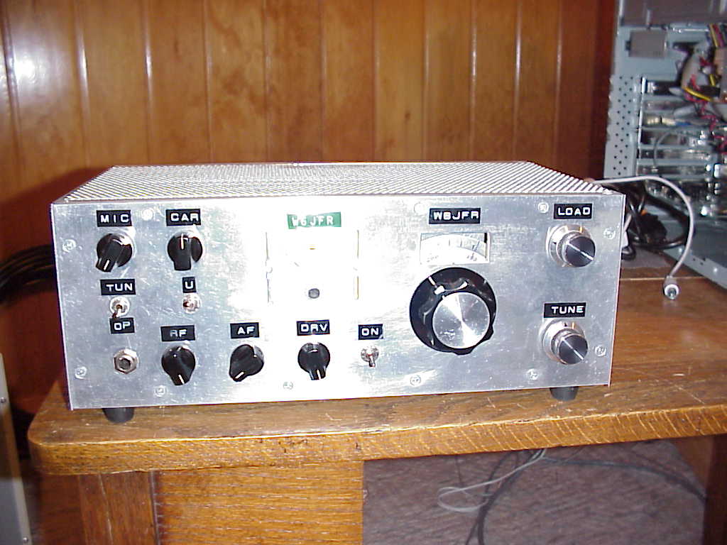
By way of background this radio started life as a TIA since it has the Hayward Kopski Termination Insensitive Amplifiers (TIA) for the bilateral amps ahead and following the 9 MHz filter. The rig also has my bi-directional amp stage that is used for the receiver RF amp and the transmit pre-driver. The driver stage is the 2N2222 driving the BD139 and the final is an IRF510. The Arduino/Si5351/Color TFT is used for the LO and BFO. The code was reworked in IDE 1.8.5. It is USB/LSB selectable and includes a Tune functionality. the power output is 5 watts. SBL-1's are used for the TxRx Mixer and the Product Detector/ Balanced Modulator. The audio amp is a 2N3904 driving a LM386. the Microphone Amp is a 2N3904

I felt compelled to rename this rig Stormy given it is "topless" where all is bared for us to see the inside details and the large "knobs" tell a tale of their own. It doesn't hurt that the motif is "Oasis Blue". This is truly the rig to ride out the "storm".


The Main Board with TIA Amps


This view above shows the detail of internal shielding between stages. By selecting two resistors in the TIA stage --it is possible to set the stage gain from 15 to 24 dB yet the Zin/out remains at 50 Ohms.The overall size is about 6 inches wide by 8 inches deep and 2.5 inches high. I have run this off of a small 12 VDC battery but obviously the transmit time would be limited. 


The Topless Bare Essentials!

In the blank space below USB and the text, when you hit the TUNE button the word TUNE appears in RED in that space and that action places the rig into transmit, while simultaneously producing a pulsed 10 second 988 Hz tone. This tone is fed into the balanced modulator after RC filtering to look like a sine wave versus a square wave coming directly out of the Arduino. No whistling or shouting Hola needed.. The default step tuning rate is 100 Hz but step rates of 10, 1K, 10K, 100K and 1 M are available.

Drop me a line and let me know what your Stormy Radio would be.

Lest I forget there was a bit of a toss up whether it should be Stormy or Karen (her sister rig) that would be chosen as the storm rig. Karen has similar specifications but a smaller size (and smaller knobs). The yellow case sure makes it easy to spot. So many rigs so many choices!


73's
Pete N6QW

Tuesday, March 6, 2018

2018 ~ Year of Transceivers:

3/17/2018 ~ Happy St. Patrick's Day!


In case you didn't know it ~ St. Patrick is the patron Saint of Engineers. He was given this title because of the "Knack" demonstrated in removing the snakes from Ireland. I jokingly say I am Mediterranean Irish but my XYL is actually part Irish as evidenced by the naming of #2 son --- Timothy Ryan.

More Woes with Windows 10. Knowing what I know today -- Never Again!

One of the things that you keep being prompted by Microshaft  to do to the point of vomiting is to enact the "One Drive" crap! This is so that any device you have will be linked to this one drive. Thus on your phone you can look at important documents uploaded to this one drive and you can see them anywhere. In theory sounds good. Down side-- Hey, you know who, you don't want to put Stormy's contact info on the one drive --it will be seen --everywhere.

Initially this sounded like a good idea --except it now rearranges your hard drive and the links and paths to documents got changed. Guess what was affected? Arduino. The sketches got decoupled from the libraries and Arduino now appeared at two locations on the hard drive. The upshot you could not even compile a sketch with out the error messages: I can't find the library. I uninstalled Arduino several times and that didn't work. So I did the regedit trick and manually removed any Arduino entry. Despite having removed Arduino with add/remove programs the registry contained 40 separate entries. These were all removed.

Here is a joke --you cannot uninstall the One Drive --it is embedded in Windows 10. There is an arcane hidden process so you can designate yourself as the Administrator and armed with that you can "unlink" your Windows 10 One Drive from other devices. This is designed so you have to take you computer back to Best Buy so the Geek Squad can charge you $300 for about 5 minutes work. Good thing I had a computer business so I know how to do some old school stuff.

I then re-installed Arduino 1.8.5 and now the program works! Unless you absolutely need it Pox on One Drive!!!!! Lost time = 10 hours. BTW you get no help.

Did find Windows Movie Maker in the Microshaft Store that will work with Windows 10. It is geared to taking your Instagram photos of your cat so you make a movie and upload that to You tube --well not directly. Where is Giovanni Manzoni (in his former life) when you need him. When I say I know a guy that knows a guy --that is Giovanni.

After a week's worth of distraction with Windows 10 and Dell --now back to some serious radio stuff.

73's
Pete N6QW

3/15/2018 ~ Recovery!

I am happy to report that most systems have been recovered from my computer disaster --not all to what I am used to with the old system. Here is an example: Formerly I used Windows Movie Maker to create videos for you tube. Surprise! Windows Movie Maker is no longer supported for Windows 10 and you are cautioned to not down load "Movie Maker" form 3rd party Internet sites as most contain malware and spyware.

Windows 10 you are told can do the Movie Maker thing with an internal app called Photo. Well after investing about 1/2 hour I was able to not upload the new video but instead a single non-flattering photo of myself. Yes Donald Trump is better looking. This is real crap!

I was not able to get aol.mail to show up directly in my email. But when you have the "knack" you do the Dilbert thing -- I found that with the aol.mail you can forward the mail to "of course" a microshaft outlook mail account. So I now can see my primary email but must respond using the outlook account.

The really huge issue was my Dreamweaver MX2004 software which no longer can be purchased but must be rented. Well again having the knack and thinking ahead. When I first got Dreamweaver I loaded it on an old laptop (Windows XP Pro) as a failsafe. I dug out the laptop and got it working -- I now can upload to the radio websites and so that is good news although cumbersome in having to use two computers --but better than spending $20 a month to rent software.There is one short coming using the laptop -- it I so old that it doesn't recognize photos on my Android phone. So I now have to down load the photos to my new computer and save them as jpegs and then using a flash drive move them over to the laptop --again a small inconvenience but no rental fees or additional software purchases.

The other good news I now have Arduino 1.8.5 working with my old sketches made in 1.0.5. The ones recycled use the color TFT --I suspect I will have problems with the LCD sketches but haven't tried that as yet. In a prior post I mentioned one Arduino sketch not archived in late February was the rework of the Big Kahuna. I was able to recreate that sketch (about 2 hours) and you can see that below. If you scroll down to the prior posting you can see that we are close to what was originally done -- the biggie its still works on the air!


I did have to purchase Office 365 but did get a bonus of having Publisher included so that is a another way to build websites. With Power Point I now can create schematic diagrams and write articles using Word. At the end of one year everything dies and you have to spend another $70. But you do get yearly updates on all of the software. I did an evaluation of the cost of Office 2016 and thought initially this was less out of pocket today.

My thoughts are now turning to an even bigger monitor than my 20 inch. A 27 inch would really make this "new rig" really shine!

Hopefully we'll be getting back to hardware building in short order.

73's
Pete, N6QW


3/11/2018 Had a Major Setback!

Losing your "main computer" to a catastrophic event is like watching your Apache Anan 200,  ICOM 7610 or maybe your FLEX 6700 go completely up in smoke. I used these model numbers since so many hams have shifted to high priced appliance rigs and  thus not many homebrew rigs catch fire and burn. So OK for my description --  it is for impact. You simply don't want that to happen!

Now about two weeks ago I thought about such an event given there were some strange sounds coming from my 5 year old machine. Taking this as a message from the Radio Gods I used  my 1 TB external hard drive and copied most things on to the external drive. So literally 99% of my precious radio files exist still today. The small percentage that were not can be replaced. So a word to the wise --back up your files. The one file I need to recreate that was not saved was the new display format on the Big Kahuna.It was done the day before the unfortunate event.


There was a bit of a trick to get this to work as there are two toggles switches on the front panel. One switch controls the band and thus you can select either 20 or 40 Meters with the switch. Actually in the code are five selections --so you can have any two band combinations. Thus you could have 80 or 15 Meters. or 40 and 10 Meters --you get the idea.

The other switch controls the selection of USB or LSB. Formerly I had the letters SB that was loaded during set up and then that switch changed the first letter to an L or a U. where that selection was made in the loop part of the sketch. Well because it is in the loop the L or U seemed to flicker on the screen based upon going through the loop. My solution for that annoying flickering was to load USB and LSB during the set up and then the small black square next to those words moves up or down to show which mode is active. The screen shows we are in 40 Meters. It took me about two hours to do this not so much about the code as it was putting the data on the screen so that it would look OK visually.

The rectangular black square in the middle of the screen has the Word TUNE appear there when the rig is put into tune. That operation also generates a pulsed 988 Hz tone for ten seconds which facilitates tune up. Can't understand why the uBitx crowd is using hardware to generate the tone for CW. One day some brilliant uBitx illuminati will proclaim he discovered a  new functionality --I have been doing this for three years.
So the recovery is in motion, but there are some terrible issues that are still in play:

  1. I still have not been able to read my main email account in Windows 10. I can do it on the Internet but not my computer --it is some sort of synchronization problem and also assigning ports to deal with aol.mail. I have done all the steps but am looking at no email on my computer for that account.
  2. Software today is an issue that was bought long ago. I have Office 2013 which now requires me to buy Office 2016 --now that is crap. Office 2016 is about $125.
  3. My Dreamweaver 2004 MX can't be loaded on this machine so I have no way of updating my websites unless I convert to another web publishing software. If you buy the new version of Dreamweaver, it is $250 or now the popular fad is paying a $20/month subscription fee. Even Go Daddy wants to charge you for web publishing software and two years is about $125. I have six websites  with them --you think I'd get a discount. That sadly will mean no website updates as that is in line behind getting Office 2016.
  4. Windows 10 is nice but actually too many choices -- the screen gets filled up with a lot of crap I don't need.
  5. I saved all of the precious Arduino files and the libraries. But most of my prior work was done in IDE 1.0.5 as most of the current crop of libraries work directly with the version. Of particular concern are the libraries for Liquid Crystal Displays --most work with IDE 1.0.5 most do not with IDE 1.8.5. The stuff I did with the teensy 3.6/3.6 needs a download from PJRC and I think that has some issues with 1.8.5. So now if I want to go back and make upgrades to older rigs much like I did with the Big Kahuna, there are likely many hours of hand hockeying to get everything to work. The process of getting everything to work with IDE 1.8.5 will be a challenge. Much like the challenge of trying to have sex with a 400 pound woman in the back of a 1966 VW Beetle Possible but not without a lot of difficulty.
  6. Uploads to you tube and connections to NETFLIX are still on the list.
  7. And on and on. Word to the wise get a Back UP hard drive and never let your computer die. 73's Pete N6QW


I am using my new Dell Computer for the Blog.

  1. The Good news --it is really fast!
  2. The Bad News -- I still type with 2 fingers!
Turn on your speakers or connect your headphones for a musical tour of some of the radio projects from N6QW. Yes you have to have the "Knack", the tools and the parts to build these rigs. It also helps to have simulation software and an EE Degree.


73's
Pete N6QW 3/9/2018

"Toobs can be used in Ham Transceivers!"


If you are 45 years old (which means you were born after 1972) you probably missed having a rig with glowing tubes sitting three inches from your nose. By 1972 solid state rigs were on the shelves of your local radio emporium and even some were soon to be fully all solid state. By the time you were 10 years old, there were few radios being sold that had vacuum tubes. You missed it.
But for some of us old timers we grew up with tube rigs. In 1959  I went to Pittsburgh to take my General Class Test (no VE's or send in box tops in those days) and after learning I passed, my first stop was at Cameradio in downtown Pittsburgh-- a Collins distributor. For the longest time I looked at a KWM-2 that had a price tag of $1250 without the power supply. To myself I said "someday". The KWM-1 the predecessor of the KWM-2 was rumored to have been installed in Gary Powers U2 Spy Plane that was shot down by the Ruskies. Single sideband had revolutionized our communications medium
In 1962 I spotted the rig below which was made by Swan Engineering and installed in a Sunbeam Alpine. Wow it was a single band SSB transceiver capable of working the world right from your car.
The Swan rigs were initially made in Benson, Arizona and later the manufacturing shifted to Oceanside, CA. Three models were offered: the SW-175, SW-140 and the SW-120 which were intended for operation on a single band. A later model the SW-240 was a tri-bander. The original lot were all hand made by Herb Johnson W6QKI (SK) in his garage. If you happen to have one with a gold face -- it is a rare one and likely from the first or second build.
I have owned literally dozens of these and still own one of the early units that was actually made in Benson, AZ. Unfortunately it is not a gold face.
Note this model does not have the meter case face over the frequency window and the panel meter is a really expensive Triplett. Note that the silk screening is kind of "crude" and not centered on the frequency window or other controls. The later unit says Swan-120 and my unit says SW-120 and Swan Engineering Co. The back panel on the above rig states it was made in Benson Arizona. But some 60 years later it still works and still puts out a nice signal.
Several Crystal Filter frequencies were used, with some at 5.5 MHz while others at 5.773 Mhz. It all must have been based on what was available. Internally there were many tube changes and it can drive you nuts. An example, some units use two 12BA6's while other used two 6BA6's -- in one case the filaments were in parallel while in the other the two tubes were in series. One version used a 12AV6 wired up as a tone oscillator while other variants just unbalanced the carrier for tune up.
Nonetheless many units were sold world wide and some are still on the air today.
In 1977 I made a decision to scratch build a Swan-120. Only this time I was opting for making it more compact in size. There were to be three modules: a  mainboard, a VFO Module and a driver / final amp module. I built it and the results were less than sterling. One problem was the final amplifier would not be tamed. In disgust I removed all of the parts from the mainboard and just kept the metal chassis plate that was approximately 4.5 X 6 inches. A couple of months ago while looking in a box of old parts I found the chassis plate, which is shown below.
Mind you the size is 4.5 X 6 inches. About a month ago an event occurred that caused me to think about rebuilding that 1977 rig -- with some changes.
The current plan is to rebuild most of the mainboard but to use a solid state audio amp for the output and instead of the tube driver and final to use all solid state devices for about 30 watts output on 40Meters. For the frequency control and BFO frequencies -- yes an Arduino + Si5351. The IF will be at 9.0 MHz using the GQRP Club filter.
Here was the first step and that was to cut some new holes in the chassis plate. Wow there ain't much metal left. I used tube shields on most of the tubes as that will help with the heat dissipation.


The new mainboard with parts installed


First Part Installations

One critical item was the Balanced Modulator transformer which was built from parts from a defunct Drake TR-4 transceiver Balanced Modulator.


Drake's original assembly consisted of a diode ring and two coils. The hardest part of the modification was making the adapter plate (piece of scrap PC Board) to mount the transformer to the chassis. Guys, bragging here, it was done on my manual mill and took all of about 5 minutes, The larger opening is about 3/4 inch square and the two slots were milled out using a 1/16 inch end mill. The Drake enclosure has a forked spring type piece of metal on either end. When fitted into the slot it expands and a couple of tangs on the assembly spring load the fit so once installed it doesn't move.

The modification of the transformer consisted of removing the four diodes and rewiring the two windings to five of the six pins. The Swan transformer had a primary winding that connected at either end to the plates on the 7360. Across this winding were two capacitors in series and the series connection was to ground. Effectively the two series caps make the total capacitance across the transformer the product over the sum of the two. Using my AADE LC meter I measured the inductance of that plate winding and found it to be 35 uHy. Now it is a slug tuned core --so any stray capacitance can be touched up with the slug. Since the BFO is at 9 MHz the capacitance across the winding = 10 PF. Thus two 20 PF caps in series will do the job. NOW I had to do this twice --so keep this in mind --luckily I caught this before applying power. I went into my capacitance storage bin and plunked out two 20 PF caps and installed them across the core and bringing the common connection to one of the pins.

At 3:00 AM my brain awoke me and said "You dummy" those caps have a voltage rating of 50 VDC. Connecting them to the plates of the 7360 that will have 185 VDC supplied to them will blow them up! We are working with Toobs guys think about higher voltages ratings of components!!!!!

With a good deal of arrogance my tribal knowledge is showing as I have built about a half a dozen tube type SSB transceivers and by and large the current technology solid state IC based transceivers are far easier to implement. I have also built some hybrid rigs where the VFO is all solid state and the rest tubes. This one below is basically a  Swan 120 with EL84 tubes in the output for a whopping 20 watts PEP on 20 Meters. I started building this the day I retired in 1997 and it took about a month. The IF is at 9 MHz and used a KVG XF-9B filter. You had to have the knack to build this rig!

Something different than the SW-120 -- the meter reads Cathode Current and was an S Meter as well. Yes this was only possible because of my extensive junk box and having many years of tribal knowledge. Not many hams today can build rigs like this -- but those reading this blog actually could. But first you must start by saying Yes I Can!

73's
Pete N6QW


The Risk of Power.

 What happens when the faithful lose faith? We don't know the result but now it is time to pop more popcorn as the interesting part of t...