Thursday, November 1, 2018

2018 ~ The Year of SSB Transceivers

Building the Si5351 VFO/BFO Board!

11/07/2018 ~ Post Mid-Terms
I have transitioned to the remote console and the result are very satisfying. You will see that shortly and I want to tie in a program on the Velocity Channel which is a cable reality show 24/7 showing guys and gals homebrewing amazing cars mostly out of junk parts. So it was with the new console which formerly housed a linear power amplifier stage.

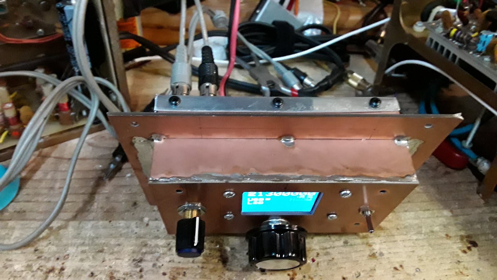
This box was fabricated from double sided copper PC board with an aluminum back cover. It was fully intended to be a totally shielded enclosure and it served that purpose when initially built as a power amplifier stage for a Ten Tec Model 540 that I acquired sans the linear amp brick. This was the prototype and a second one that was built was installed in the Model 540 which I later added a Digital Display effectively making it a Model 544. So I had a spare shielded enclosure in the "junk box".

When you undertake these zany projects there are often unexpected by products and one of those was RF noise coming from the Arduino/Si5351. A click click click sound would be heard as the Arduino went through loop and further evidenced by one of the on board LED's blinking at the same click rate. My thoughts turned into a completely shielded Arduino/Si5351 to see if it could cure the problem. The next light bulb was the enclosure I built that was hiding at the bottom of the junk box. TRGHS -- it was serendipity on two accounts as the enclosure was big enough to house the components and provided a neat "front panel" and the shielding solved the "click" sound. there are no more click sounds!

Should mention that I only heard the clicking when the antenna was disconnected or the band switch was in a position unrelated to the antenna being used. I did not hear the click sound on the transmitted signal but I did know it was there on the receive side (with no antenna).

The build itself has the display, encoder, band switch and USB/LSB select in one half, while the Arduino/Si5351 plus LO, BFO and power connectors on the back panel. This is a good way to do it since any reprogramming of the Arduino entails simple removing the back panel and you have access to the USB to Serial interface. [See the photo below.]

We are about to make some final adjustments and then we will button things up.


73's
Pete N6QW
11/06/2018 ~ Election Day

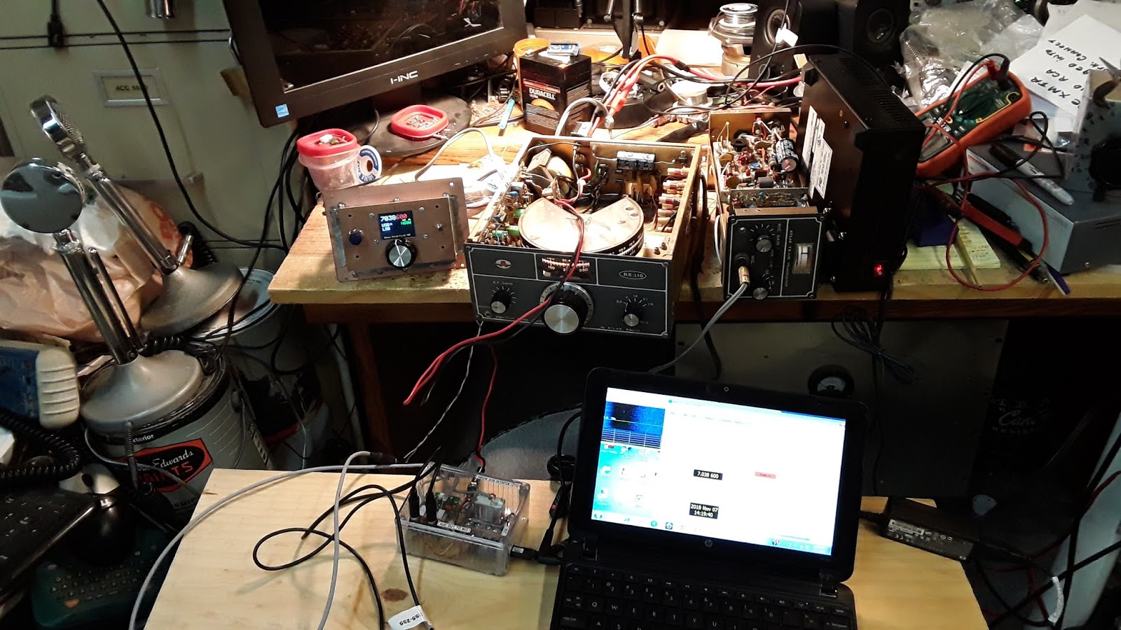
Yes I did vote (by mail) and so today I am electing to work on the Atlas RX110 and TX110. I just couldn't resist hooking up the Atlas Twins to 40M WSPR. I have a lot of data from other 40 Meter Rigs and thus can compare A to B. I am encouraged by what I see. My main concern was the transmitter, since it had problems and while I have moved forward I am still not there with the Twins where I think they can be.


Below is the hot off the press record of the Atlas TX110 on 40 Meter WSPR at 5 watts -- heard in South Africa. I was also heard in Japan.


You probably would never see an article in QST about "rebooting a Atlas RX110/TX110 with a Si5351" so you can work WSPR and as a bonus FT8. Even the Digi-Adapter is homebrew . Possibly the reason you won't see such articles is that the big commercial advertisers would not approve of hams building (or rebuilding) their own gear. This is a pure example where new technology let's the average ham to be able to work FT8 with really old boat anchors. All it takes is a bit of learning from the Internet (and blog's like this) and a desire to move out of your comfort zone. 

Then we have the new ARRL CEO wondering why the hobby is stagnant?


73's
Pete N6QW

11/3/2018 ~ See the You Tube Video of the Arduino/Si5351 Prototype Working with the Atlas Twins!


I frequently receive inquiries about building the Si5351/Arduino boards and the last blog posting was sort of a stop gap measure to answer some specific questions; but I am sure for those who don't like to read or to look at photos that was not enough. Or alternatively they don't want to invest the time to read and study. 

Note, not all Si5351 boards are a simple drop in the circuit and move on. I use the Adafruit boards or clones made by others based on the Aadfruit design. Boards are available from Hans Summers website; but he uses a different clock frequency than the Adafruit or Clone boards. Thus if you have the Summers boards you will need to make some adjustment for his clock frequency. I don't know how to do that and got lost in the process that was described to me. So if you have those boards, contact Hans Summers for any adjustments that may be required. (Possibly nothing.)

Recently I was asked about the source for the Color TFT I use in my projects. Despite having a series of webpages on the Sudden Transceiver on my www.n6qw.com website with one being specifically about the Arduino/Si5351 and a link to the supplier and a matrix of pin wiring for the several Color TFT's --I get the question where can I buy one? 

Let us start at the beginning of the current Arduino/Si5351 build. Yes there is another $100 "bought on eBay commercial radio" on the bench going through the Pete's reboot process. For about $100 I managed to purchase the "Atlas Twins" radio set which is comprised of two boxes. The first box is the RX110 Receiver which has embedded within it some of the circuitry needed to convert it to a transceiver. The RX110 is a five band SSB receiver complete with a built in AC power supply. It is a single conversion design with a 5.595 MHz six pole crystal ladder filter. As is the case with many of the economy rigs of this vintage it operates on LSB on 80/40 Meters and USB on 20/15/10. Thus only one BFO crystal is used. There are no heterodyne crystal mixing schemes! To operate on 10 Meters the VFO is running at 24 MHz and for 20 Meters it is running at 9 MHz and needless to say drift will always be a concern. [NOTE: Go to www.n6qw.com and there is a detailed link on the Atlas Twins.]

The RX110 can be operated standalone or mated with the TX110 module that now makes the unit into a complete five band transceiver. The TX110 is about 1/2 the physical size but with some slight of hand and additional mechanical hardware the two boxes are physically mated as a single unit. All interconnect wiring is done through a 12 Pin plug on the back of the RX110 and where the antenna is normally connected to the RX110 and jumper plug connects the antenna port to the TX110. The TX110 in the normal configuration is a QRP type rig with about 10 watts on 80 Meters and a lot less on 10 Meters. There was an internal add on power amplifier "brick" that would boost the output to over 100 watts on 80M and perhaps about 50 watts on 10 Meters. 

All I can say is that there was a lot of internal heat in that very small box. I say this because of my observation of the actual space in the TX110 and the fact that a prior owner hack sawed openings in the case on the bottom and top of the case where the amp board was installed. Crude is a really good word. It was obvious that my unit had the amp board but it was no longer installed. Without the amp board a jumper cable is installed so that the rig can be operated "QRP". In passing, a bit 'hokey" but there are two bands switches so at times you have to remember that both switches must be on the same band!


I don't buy things without having some specific plan for the reboot. I saw the Atlas Twins as a spring board to install the Arduino and Si5351 to enable two things: 1st is an accurate and highly stable LO generation complete with Color TFT display and 2nd to provide USB/LSB capability so that the rig could be used on the digital modes on 40 Meters. Thus why I am spending time on this post to take you through the Arduino/Si5351 sketch process and then the actual building of the hardware.

Fortunately, manuals for the RX110 and TX110 exist on the Internet and so I didn't have to guess some things. The original VFO/BFO scheme was that the VFO operated above the incoming frequency (by the amount of the BFO) for 80/40 Meters thus subtractive. For the higher bands the VFO operates below the incoming frequency (by the amount of the BFO). So on 80 Meters you have a 9 MHz range VFO and on 20 Meters a 8 MHz range VFO. One crystal BFO frequency would yield LSB on the lower bands (sideband inversion) while giving USB on the higher band (no sideband inversion). Thanks Herb.

A single three  ganged band switch on the RX110 simultaneously switches in the correct VFO coils while connecting the input and outputs of the Band Pass Filter. My initial thoughts were to "rip out" the VFO section, install a Color TFT is the frequency window and install on small toggle switch on the front panel for USB/LSB selection. Inspection of the actual hardware led me to conclude a separate small "Remote VFO" console that would house the 3rd band switch to shift the Arduino range, have the color TFT and the USB/LSB select. I might even include the Mic connector and a stereo headphone jack and even the CW key --it can do CW. This way for digital operation in my new configuration, all connections are made to the Remote VFO. I am even considering the use of a commercial sloping front panel aluminum box from Bud or Hammond. 

Long ago with a lot of help from others I decoded how to band switch an Arduino for five band operation and thus minimum  sketch development was needed. For the Atlas Twins all LO's will be above in frequency and the BFO will be switchable above and below the Crystal Center Frequency by an initial starting point of 1.5 kHz. The RX110/TX110 Manual describes the setting of the BFO by visually observing the power output at 1000 Hz and then 300 hertz. A drop of a specific level between these frequencies is the BFO set point without identifying the actual frequency. This may require several runs to get it right but we will be in the ball park perhaps not in the exact seat on our initial attempt. So we have the sketch and now to the hardware.

Having a standard layout for the Arduino/Si5351 makes for rapid prototyping and minimizes the footprint. The last blog post talked about using the Nano as that offered the most bang for the buck. Recently I bought a three pack and the cost was $4 each ($12) so that is very cost effective. Thus I will use the Nano and the Adafruit board without connectors. Connections to my standard Board are made using Pin Header Sockets and Connectors. A total of 20 connections are made to the board as follows:


  • Four pins are used for the Encoder and Step button
  • One pin (to Ground)  is used for USB/LSB Select
  • Seven Pins are used for the Color TFT Interconnect
  • Six Pins are used for the five position Band Switch
  • Two pins are used for the Source 12 VDC Input


The below photo shows how using #30 bare tinned wire that I wire from the Arduino socket to the 30 pin header (15 each side). Then wiring is taken from the pin headers to the header sockets as shown in the photo above this one. Thus I have two forms of access to the Arduino with one being the pin headers which fit standard jumper plug wiring and the second the header sockets. I can't tell you the number of times I wanted to see what is happening on an Arduino pin and posing about on the top of the Arduino board you risk shorting something out. Thus I can safely insert a jumper wore and measure to my hearts content. Two bolts/nuts secure the Si5351 to the perforated board and I will wire wrap the connection to this board. At this point the signals are digital not RF!


As I add more of the wiring I will add shots to this blog post.


Yes Virginia another transceiver in the works only this time a reboot of the Atlas Twins. In summary the plan is to leave the internal VFO/BFO intact but disconnected and all operations will be done with the Remote VFO. This modification could be noted for other Atlas owners (Models 180, 210, 210X, 215) where you can have a Digital VFO with a Color TFT display.

I have had the Atlas Twins on the air using the stock VFO/BFO and have made about a half dozen contacts with most on 40M and one on 15 Meters. The TX110 needs some work to get the power out up to spec. But I was surprised at the stability of the Analog VFO. The main Analog VFO issue is the actual readout (too macro) and of course there is a bit of a drift. It would be a near impossibility to set WSPR frequencies with the analog VFO!

73's
Pete N6QW … Stay Tuned for more innovation and creative thinking. You are learning from the Master!

Tuesday, October 16, 2018

2018 ~ The Year of New SSB Transceivers

10/28/2018 ~ Questions about Si5351

 Visit www.n6qw.com 


This is not an Arduino/Si5351 but my Pasta dish!
Those are fresh cherry tomatoes in the sauce with
fresh Basil, loads of Garlic and the key ingredient
Virgin Olive Oil and of course Angel Hair Pasta
http://www.pastapete.com


With the publication of the Sudden Transceiver project in the GQRP SPRAT #178 (for those who have received their SPRAT --some of us are still waiting) and are undertaking the project a couple of questions have arisen. One specific question is about "How do I build the Si5351 Oscillator and connect to the display". The Sudden project on my website has a section on building and wiring the Arduino and Display but for someone undertaking this as a first project I am sure it leaves a lot questions. Thus today's posting.

Firstly, having built quite a few rigs with the Si5351/Arduino (think close to three dozen) purely by accident you find some things that work well and some that are absolutely never do that again. So here are some "experience points" I will share with you.


  • The are many variants of the Arduino including the Mega 2560, the Uno R2, the Nano R3 and the Pro-mini. My shack has transceivers containing at least one of these boards. Typically we are always trying to make our rigs compact and so the larger boards like the Mega 2560 and the Uno R3 are like Brown Shoes with a Tuxedo --not a good fit because of their size. The Mega 2560 however is a jewel when you need 10X the program space of the smaller units and a lot more IO then is when you need the mega. The Uno just is a weird shape and size. That leaves the Nano and the Pro-Mini. The Pro-Mini is physically smaller mainly because the USB to Serial functionality is not on the board. Thus when you program the Pro-Mini you need a special cable that has the USB to Serial interface built in. The Pro-Mini also lacks the 3.3 Volt on board regulator. So if you want to use the Pro-Mini with a color TFT that requires 3.3 VDC you need to add an external 3.3 VDC three terminal regulator (or a hokey voltage divider resistor bank). You now have added more space requirements. The Nano by far offers a the most capability in the smallest package. Having not only all of the features of the Uno R3 at about 25% of the size. Thus I have standardized on the Nano as the controller of choice. Incidentally it does have the onboard USB to Serial interface and the 3.3 VDC regulator.
  • Boards. I have more or less standardized using perforated boards as a basis for the constructing the Arduino and Si5351. Now I have a standard layout which I use all of the time. Certainly you could come up with PC board and have a bunch made for you in China and that has been done by many. But small size standard perforated boards with solder pads can be found inexpensively from many suppliers. Some come with four mounting holes already installed in the corners. An important feature of my layout is that the arrangement enables me to gain access to the Arduino USB to Serial connector from the side of the chassis. You will always want to tweak the program and thus being able to easily plug into the controller is a real plus.
  • The method used on my boards is to use sockets for the Arduino and the Si5351. The socket for the Arduino is two rows of 15 Pins each. From each socket side I then install a row of pin headers and make the connection from the socket pin to the pin header using #30 bare tinned wire (use wire wrap wire with the insulation removed. This arrangement now affords me access to all of the Arduino pins and I can simply install premade jumper wires to the pins. As an added step I also use an additional set of pin headers with plugs for items like the encoders. A four pin header enable connection to the two encoder pins (A/B) the Ground and the step rate push button. I use a two pin header to bring power to the board and from there is a 9 VDC 1amp regulator supplies all the power for the Arduino/Si5351 with the Arduino Nano having both 5 VDC and 3.3 VDC onboard regulators which further supply power for the Si5351 and the Color TFT. In one case where space was a real premium, I bypassed the socket and wire wrapped directly to the pins of the Arduino. I smoked the Arduino and had to completely rebuild the whole board. Had I used a socket it was pull out the old plug in the new.
  • In one Arduino/Si5351 I made the whole shebang an integral assembly where the holes used to mount the Color TFT to the panel instead of nuts on the bolts had aluminum pillars mounted to them and then I mounted a sub-chassis where I installed the Arduino/Si5351 so that everything essentially is mounted to the font panel -- that was not a plan but a solution to a space problem with lack of space on the base plate to do this. It makes servicing terrible and violates my DFMA approach (Design For Manufacturing and Assembly.
You get the idea -- the perf board  that seems to work is about 2 X 3inches.

73's
Pete N6QW

10/25/2018 ~ What Filter Frequency?


Bill, N2CQR on his SolderSmoke Blog several days ago had a link to this blog and a question was asked about what filter frequencies are used for homebrew rigs and was it simply a matter of what you had in the junk box? 

I posted an answer on the SS Blog to see this blog for the answer. Well the answer is both a YES and NO. So you have this surplus filter or a bag of crystals and want to build a rig and so you are off and running. Add to that what may be the availability of the filter surplus or how cheaply you can get the bag of crystals. BUT there are other factors and I will outline those now.


  • You have this really neat Collins Mechanical Filter at 455 kHz that was given to you by a friend. Now is where the design topology comes into play. If you have chosen a single conversion approach that Collins Filter will top out at anything beyond 75 Meters because of the image problem with the low IF frequency. Using the Collins Filter will most likely dictate a dual conversion design. So it is more than just the filter.
  • In my junk box I have a pair of 16 MHz Crystal Filters, one for USB and the other for LSB. The approach used with individual filters is that you hold the BFO frequency constant and switch the appropriate filter in line depending on what side band you select. Well these filters are over 40 years old and with aging have drifted so that the BFO that works with one filter will not be correct for the other. If you are using a fixed crystal BFO that is a problem. Since I use an Arduino/Si5351 when I diode steer the correct filter I also input to the Arduino to shift slightly the BFO signal. But that takes a lot of fiddling to get that to work properly. This is compounded by the higher IF frequency (especially a problem if you are homebrewing a filter). Most crystals are specified as having a frequency stability of 50 PPM. which means at 16 MHz there could be a stability issue of 800 Hz. If you use a filter at 4 MHz then the stability issue is only 200 Hz. Even commercial filters have this issue and older ones in particular may have drifted off the Center Frequency.
  • IF frequencies and ham bands. One of the most common crystal filters of old was at 9 MHz and when the major ham bands were 80, 40, 20, 15 and 10 not an issue. But with the introduction of 17 Meters and single conversion that means the LO would be in the 17 Meter band. 9 MHz IF and 9.150 LO = 18.150 MHz. the second harmonic of the LO would be 18.3 MHz which is hard to filter out of LPF. Some manufacturers (Ten Tec) used an LO of 27 MHz so that on a down mix it would give the 17 Meter band but there were some concerns about this being a really good solution.
  • Cheap filters may be cheap because they are bad and just because you paid $80 on eBay for a filter it may be bad too. So you are somewhat at the mercy of Caveat Emptor.
  • There is a band of filter frequencies that seem to prevail. Some literature suggests that a range of suitable crystal filters (Collins are mechanical filters) is 2 to 12 MHz. Of the ones I homebrewed I found my best filters were either 4.9152 MHz or 5.185 MHz. Several rigs of mine which appeared in QRP Quarterly used these filter frequencies. This range has greater stability and avoids the 17 Meter problem. If you check the Elecraft K2 specifications you will find a 4.9152 MHz filter hidden in there.
  • In the days of old, the dark ages  (read Analog VFO's), the LO frequency was an issue as well. Typically to achieve frequency stability and reduce (I didn't say eliminate) drift the VFO operated in the 4 to 6 MHz range. To operate the various bands, the VFO signal was mixed with a heterodyne crystal oscillator signal to reach the need injection frequency ranges. That in itself now introduce a whole range of issues. 

So there are some SAFE Intermediate Frequencies and some that are not. The filter you have in the junk box may not work well in an all band rig but may work fine in a single band rig provided the band selected is compatible with the IF used.


73's

Pete N6QW


The New Heathkit Filter Based SSB Transceiver is Alive and Working on 40 Meters!

Great Signal Reports!
Great Fun!
Great Satisfaction -- Homebrew Heaven!


This Video Shows the Detail of the New Rig!

73's
Pete N6QW

Friday, September 14, 2018

2018 ~ The Year of SSB Transceivers

Why Build Another Transceiver?

10/16/2018 ~ See the latest Video on the Heathkit SSB Transceiver


10/10/2018 ~ Breaking the Guinness Book of Records.

1014/2018 ~ The Heathkit Rig is on the Air

Running 100 MW with just the Driver Stage the Heathkit Rig is doing WSPR. Just installed a Refined Driver Stage with the 2N2219 -- a healthy 100 MW. The Transistor with the heatsink in the lower left corner is the 2N2219


This is the WSPR Data at 100 MW


Get off the couch and start soldering!

73's
Pete N6QW


The SMD board above is the Plessey Bilateral Amplifier in surface mount. This is the work of Nick, G8INE who recently acquired a CNC machine. You can see the small size as compared to the ADE-1 DBM. Nick has done a superb job --and he reports it has been proofed and is a working board!

If you go to my website www.n6qw.com under the Sudden Transceiver link there is a link to G8INE and he has offered to provide the Gerber files for this really small board. Thanks Nick!

Pete N6QW

What are you thinking -- I am not trying to break any world record? My XYL asked me that question today -- why are you building another rig? Followed up by a snide comment that I had so many rigs now why do I need another one. Well the answer plain and simple because I can! 


For the longest time in the late 60's early 70's my success rate with homebrew SSB transceivers was miserable. At that time I lacked the more sophisticated test gear and let's face it some of the technology wasn't that great. Crappy Analog VFO's were high on the list of impediments! I also had to work and to give a fair share of my time to the family -- it is that balance thing.

But today that is all changed --better test gear, better technology like Digital VFO's and a bit more time. The latest project is to demonstrate that some of the components out of boat anchors can indeed be reworked to provide a very modern, very capable rig. I looked through eBay and have seen many crystal filters from heathkit, yaesu, icom, kenwood etc that can be had at very reasonable prices. A good friend just picked up a heathkit filter like the one in my latest rig for less than $15 including shipping.

Previously a big problem was having only the filter did nothing for you without also having the BFO crystals. With the Si5351 -- that no longer is the problem as you can have any BFO frequency between 8 kHz and 220 MHz-- that should cover a lot of filters.

The other factor is that with the currently popular bilateral or as I have demonstrated in the Sudden Transceiver, the single pass with relay switching the total amount of components needed can be had for very little money. Imagine a whole bilateral amplifier strip complete with filter for something in the $20 to $25 range. A digital VFO with BFO and color TFT is another $25 -- a homebrew complete rig for about $100 is a reality. Even less if you have a big junk box. You are only limited by your imagination.

BTW the Digital VFO includes two independent VFO's, USB/LSB select and a tune function. 

Stay tuned for more details on the heathkit SSB rig from the N6QW Laboratories.


73's

Pete N6QW


10/09/2018

The Heathkit 40M SSB Transceiver (N6QW Version) Hears Well!


The N6QW SSB Transceiver Complement:

Receive Section: (Currently working)

  • 2 X 2N3904 (Two SMD)
  • 2 X 2N3906 (Two SMD)
  • 2N3904 Rx RF Amp (Future AG303-86G)
  • 2 X ADE-1 (DBM)
  • 3.395 MHz Heathkit Surplus Filter
  • NE5534 Audio Pre-Amplifier
  • LM 380 Final Audio Amp
  • Arduino Nano
  • Si5351
  • 160X128 Color TFT
  • Band Pass Filter

Transmit Section: (Under Construction)


  • Transmit Pre-Driver, AG303-86G (MMIC)
  • Transmit Driver, 2N2219
  • Transmit Final, Mitsubishi RDHF RF FET
  • Low Pass Filter


This transceiver is on par with the Sudden Transceiver and yes Virginia you can even find some of the circuits in EMRFD. The 2N3904/2N3906 bilateral amplifier circuit (from Plessey) as used in this rig came from there. So it does have street creds for those who think that they will only look at circuits coming from that publication. 


73's

Pete N6QW

10/08/2019 ~ Columbus Day. Chris discovered America (or one of the ones that did) and now you can discover how to use old boat anchor filters in your homebrew SSB Rig!

You can even do WSPR with the new Heathkit Rig. This is receive only using the N6QW Digital Adapter. 


New transceiver  Heathkit 3.395 MHz crystal filter with two Plessey 2N3904/2N3906 bilateral amps. NE5534/LM380 Audio Amp, 2N3904 Mic Amp, 2XJ310 Relay Switched Rx RF/Amp & Tx RF ( a 2N3904 Rx RF for this video). 2N2219 Tx Driver, Mitsubishi RDHF FET for the Final and 2 X ADE-1's for Rx/Tx Mixer and PD/BM/ Arduino Nano, Si5351 and Color TFT.

Some thoughts on switching the BPF's and LPF for 4 Band Operation. On several of my rigs that were multiband and used a common buss for the filters I found bleed through problems and difficulty with drive through the BPF at higher frequencies. With six relays this give 4 bands with either the BPF or LPF and provides better signal isolation over that with a common buss. It will take 12 relays ( @ 60 cents a piece) for four bands and switching both the BPF and LPF. Bottom Line: only one set of BPF's and LPF's connected in line at any one time!


73's
Pete N6QW

Friday, August 24, 2018

2018 ~ The Year of SSB Transceivers

FT8 & WSPR on your Homebrew Rig!

For several months now I have been working on a new SSB rig that will be the subject of a couple of articles in  future issues of the GQRP Club publication SPRAT Magazine.


Run don't walk if you are not already a member of the GQRP Club so by joining you can gain access to the articles. Most of my operation is on SSB but I have come to recognize that many in our ham community have moved over to the digital communications dark side and therefore challenged myself to enable my SSB rig design to "do digital". I am happy to report that I have been successful in running both WSPR and FT8 from the new rig.

All that was needed was the software WSJT-X, a $10 (delivered) sound card interface board, some cables and an old computer with a serial port DB9 connector. That is it. 

With technology advancement comes change. Most new computers do not come with a serial port and thus that presents some difficulties in using the sound card interface device. A tour of Adafruit Industries webpage revealed a product that provides a USB to Serial interface device that has as outputs the DTR or RTS signals (either one) that will key the transmitter. It is a modest price ($15); but opens the door for possible uses with a Raspberry Pi3B or an Asus Tinker Board. WSJT-X  comes in Windows and Linux distributions so there may be a possibility for a very small (and portable) FT8 station. I have ordered one of the units and you can read about it here https://www.adafruit.com/product/284

Here is the interface board kit.


But the real proof is how it works on the air. Below are some screen shots that document the contacts I had. In the WSPR log you will see an entry from VK2ALR when I was spotted 7500 miles away running 5 watts on 40 Meters.


But the most Buzz today is about FT8. So I had to try my hand at that mode and so far have made two contacts. Here is a log of the 2nd contact made this afternoon.


Now I must confess that the FT8 is almost like remote sex. Push a button and the computer takes over and makes the contact. So no long rag chews here. But FT8 levels the playing field using low power and modest antennas.

I am in the process of reworking the sketch for the VFO (it has two). One VFO will boot up normal at 7.2 MHz and the second one I will program to boot up on 7.074 MHz. Thus, flip the VFO select switch and flip the rig to USB and you are on digital!

This is exciting.

73's
Pete N6QW

Thursday, August 9, 2018

2018 ~ The Year of SSB Transceivers

Something for the SDR Crowd!


You too can build your own SDR Transceiver!

Second Generation Main Board


The board above is a second generation board and contains the two ADE-1 Detectors and the Modem coupling transformers, the divide by four 74AC74 and to be installed is the band pass filter. If you look close you can see the ferrite core balun used to split the signals going into the two detectors. This is a deliberate attempt at isolating signals and keeping things neat and tidy. I am thinking about a separate enclosure just for this board. Later today I will install the bandpass filter with the intent that it may be used at 9 MHz with a possibility of a different front end. You will have to stay tuned for this.

How about using the SDR on WSPR?


While I can claim I built this rig and added several modifications, by and large the credit goes to Charlie Morris ZL2CTM for his design and software development. You can follow ZL2CTM on YouTube and he has many videos and tutorials!

The bottom line is how your signal sounds AND LOOKS  at the other end. I am really surprised at the number of hams that use either an SDR rig in the shack or use an SDR receiver on the Web for the receiving end of things. Not too many are using a homebrew SDR! Thus it is not unusual to hear that my signal looks really good. To date I have made close to three dozen contacts including a 8000 mile DX QSO with a station in Australia --on 40 Meters. My usual set up is the rig followed by a 100+ watt Solid State Amp kit from CCI and then the Heathkit SB200. Based on my upgrade of the SB200 I typically see in excess of 600 Watts to the antenna. That is a smoking signal!

My 40M antenna is a droopy dipole and that means if I spent a bit more time on the antenna I would hear and work more stations. The center pole is up about 25 feet and the length is 98 feet 3/2 wavelengths on 20 Meters. It is in the shape of an L as it runs along the back end and one of the sides of the lot. The fiberglass support pole is strapped to the tree.


But let us start with the Block Diagram of the basic hardware. Beyond this I have a transmit Driver Stage with a 2N3904 and 2N3866 and the Final amplifier is a IRF510. The relay Switched J310's and the audio amplifier (2N3904 + LM386) are located on the main receiver board. One other item needed to make this play is another bit of hardware from PJRC and that is the sound isolator which I think is nothing more than a modem transformer sealed in a box. The Codec board needs to keep the DC and AC grounds isolated and this is what this device does. In line you hear the amazing SDR signals -- out of the circuit and straight through coupling --garbage!!!!!! It cost $6. One of my modifications was to add modem coupling transformers following the ADE-1's --again the same issue as with the sound isolator. You simply cannot ugly construct this rig and have expectations for success! You will note the date on the block diagram and you will realize this has been a year in the works.


 (R1 is for Simulation Purposes in LT Spice and not used in the final circuit)


The above circuit forms the basis of the driver stage and has been used on many transceiver projects. Ignore the notes and focus on just the 2N3904 and 2N3866 parts of the circuit.


This circuit is used for the Final RF amplifier stage on the SDR. Now a modification to this circuit to accept the Mitsubishi RDHF RF FET would include the replacing the Zener with the 78L05 three terminal regulator and inserting a LED in between the Ground pin of the 78L05 and Ground. which raises the output voltage > 6 VDC. A higher bias level  is needed for the RF FET. Typical output is 6 Watts but higher levels close to 10 watts may be experienced. All other circuit constants remain the same. this is an easy conversion. What is so cool about the LED -- when the circuit is biased "ON" the LED glows --more lights, bells and whistles.

Below are a couple of additional schematic circuits for the SDR Rig with the first being the steerable Dual J310 Amp stage. R3 is for simulation purposes and not used in the final build. R7 is as noted is a 10K trimpot connected as a variable resistor. Note the schematic shows the amp stage amplifying from left to right but the actual install has the amp stage direction going from right to left. I just know someone will install it backwards and then email that it doesn't work. RTM!


The Below sketch shows the modem transformer install.


Now you ask why would you do this when you can buy the IRF510 for about 80 cents and the RDHF is about $5. Well it all depends if you want to operate above 20 Meters. The power output drops off at higher frequencies with the IRF510. So it is all about choice of operating frequency.
Why even the microphone was homebrewed (a first for me). I bought this electret Lavalier style microphone from All Electronics. It is a superb microphone but somewhat costly -- about $1.15 with 15 foot cord. It does not have a PTT switch so I built the PTT using a microswitch I had in the junk box. Starting with a piece of scrap 2X4 about 6 inches long I milled out a cavity so I could mount the microphone and PTT. The remainder of the 2X4 was simply sawed off and ths is what was left. It is palm sized. See below. Aside from some splinters all went well. Not bad for some junk parts a piece of scrap wood and a $1.15 microphone. If you look closely you can see the PTT button sticking out of the case. Not very elegant but it works.
As of 8/11 I have had about 3 dozen contacts including one this morning with a VK station on 40M.

My homebrew Electret  Microphone: (This is one heck of a buy!)


Started like This...


This rig was built based on the design/software from Charlie Morris, ZL2CTM. This is a truly amazing rig as no external computer is required to make it play. While something more than an Arduino Uno R3 is required to make it work,  the Teensy 3.5 and the Audio Codec Board from PJRC will make it stand up tall. This is a $150 class rig but offers many possibilities for use on multiple bands or as I have on the drawing boards a hybrid Crystal Filter/SDR rig.


73's
Pete N6QW

Chick Magnets

POTA, The new Chick Magnet (Dream Version)! POTA, The new Chick Magnet (Reality Version)! It is all about Contests and Operating. (Images AI...