Friday, February 8, 2019

2019 ~ Building SSB Transceivers

The Building of a SSB Transceiver ~ You can do it!

2/22/2019
At Christmas my 3rd son gave me a transducer speaker that mounts to a piece of foam board and I sit here amazed at the sound reproduction. The amp driving the speaker is the 2N3904 and LM386. So it will provide more than just headphone volume (with a 100 Ohm resistor installed). I received a comment about the 100 Ohm resistor and just for fun substituted a 10 Ohm in the LT Spice simulation and saw no difference in the output curves. The short video tells much.


Pete, N6QW

2/21/2019 ~ Go Daddy Now Fixed! The audio Amp Schematic is on the website.

2/20/2019 ~ Problems with Go Daddy!!

For over 24 hours I have been trying to upload updated schematics and information to my n6qw website. It seems like Go Daddy who hosts my website has some sort of issue with a windows server. One solution that offered was for me to spend more money and move over to a Linux server OR just wait until they get around to fixing the problem. Not only is it a cost issue but also I would have to start from scratch and rebuild all five of my websites. This makes about as much sense as declaring an emergency so the emperor can have his wall. 

My alternative is to wait a bit longer to see if they can resolve the problem or just post the info here. Here is one of the updated schematics. Perhaps if any of you have a Go Daddy account you may have the same problem.

Pete N6QW


2/18/2019 ~ Toroids are not self shielding!

I noted that after installing the shield on the left hand side there appeared to be a detuning of the band pass filter. Despite what many have said toroids are not necessarily self shielding. 

When I installed the side piece, I thought there was a sufficient space gap between the steel based side panel and the T-68-2 cores. There was not and so the BPF was being detuned. There just was no way with the side panel in place to re-peak the BPF to the proper value unless I followed the practice espoused by Ian Roussel (Full Custom Garage on the Motor Trend Channel) which is make a hole.. The "A" change was to cut about a 1 and 1/8 inch round hole in the side panel stiffener right over the BPF. This accomplished two things. Firstly it reduced the effects of the steel on the BPF and secondly to provide access to the trimmer caps so that the BPF can be tuned with the steel side piece in place. Worked perfectly -- the hole does not affect the stiff properties of the side bracket. We are good to go. The 2nd photo below shows the side piece without the access hole. You have got to love when a plan comes together!

Pete N6QW


2/17/2019 ~ Be sure to visit www.n6qw.com where the project is documented  and new schematics have been added over the past two days. 

Learning to Hem ~ No we are not sewing!!!


In keeping with trying to use stuff I already have knocking about the shack we now address a common problem with homebrew construction: making or buying a case enclosure. The problem is compounded by the fact the front panel is  from the former 30M CW transceiver project that was a QRP Quarterly article. But the back panel came from a transceiver that was rebuilt at least three times. 


Now for the disconnect. The front panel is 4 inches high and the back panel a mere two inches. Standing alone the front panel flexes as you spin the encoder --not a good plan. Thus to stiffen things we need to connect the front panel to the back panel to add rigidity. We essentially have a trapezoid and how to fabricate those two pieces, one for each side, and not spend a fortune on material.

One of my currently favorite TV shows is the Velocity Channel (now Motor Trend) and my new hero is Ian Roussel of Full Custom Garage. This guy uses what is at hand and often comes up with very creative solutions. In one episode he needed a round metal structure to house the odometer that was being affixed to a new dashboard. He spotted his dog's water bowl which it turned out was stainless steel and just the right size. The poor dog now drinks out of a plastic dish. But it is that sort of thinking we need to employ when we fabricate our homebrew rigs.

A trip to Home Depot yielded a piece of galvanized metal flashing that was about 8 X 11 inches. The price was $1.14 and was enough material to make two sides. But wait you are thinking that stuff is awful flimsy. True; but if you bend it over along one of the seams --it becomes rigid. A pair of Tin Snips, a metal straight edge with scribe and a bench vise is all that is needed to make these very durable side braces. The galvanized metal can be soldered as well as painted. Thus the bending over and doubling is known in the fabrication world as "hemming".

The first item on the list should be a manila folder that will serve as a pattern to overlay on the sheet metal and provides a template to scribe the outline. Keep in mind you have right and left hand pieces and thus you must flip the pattern over to draw the scribe lines for the different sides. The 1st photo below shows the template of the sides and you can see the bend line for the hemming. On either end add 1/2 inch of material that is bent over and will provide the anchor points to the front and back panel.

You might have to "play a bit" with the metal bending so get two sheets of the material. The finished rig is a far cry from the boards screwed down to work bench as it was initially built. Nice looking Rig, Pete!

Ian Roussel would be proud.

Pete N6QW


2/15/2019


2/13/2019

[2/11/2019 I have started publishing schematics for the Simple SSB on my website at www.n6qw.com. Although it is doubtful that many (if any) would take up the fabricating of this rig, there just may be one or two who have an interest.] 


Just the other day I was having a very nice QSO with Gene W6QFU and we exchanged our station line up. W6QFU is lucky in that he just recently acquired a very nice ICOM 7300 and has joined the ranks of perhaps over 100,000 other hams world wide who now have that rig sitting at the operating position. Some would suggest it is an appliance rig; but at the same time it is a great sounding rig that undoubtedly is very popular and the current price point puts it in reach of many hams. Guess there is a link to price point and the numbers in shacks around the world.

On my end --yes, yet another new rig just finished and W6QFU was the third contact on that rig. So I was anxious to see how it held up. Well I might add...

ARRL as previously reported will start a new podcast one month from now called "So What Now?" A possible answer to that question (or perhaps it is a challenge)  is to suggest you build your own SSB transceiver. Trust me what I am suggesting you build is not in the ICOM 7300 class; BUT it puts out a respectable signal with a rock solid frequency stability and it is something you built and can be built for about $100. [YMMV depending on how much junk you have in the junk box.]

But let us go back in time to review SSB transceivers starting in the late 1950's and early 1960's. BOOM there was an explosion of technology in that time frame starting with the Collins KWM-1 and KWM-2 (the cost --read a years salary for most middle class working folk) to more modest rigs that were less costly. Heathkit did much for the hobby in offering single band transceivers that could be had for about $100. I remember being on Midway island (actually two island Sand and Eastern Island) in 1963 where a fellow Navy ham on Eastern ran one of those rigs into a 13 dB gain Rhombic antenna pointed at the US. Everyone wanted to talk to him--firstly he was DX and secondly that gain antenna took that 100 watts and made it look like more than a KW (like 2KW and you can check the math [10*log(2000/100) = 13dB]) But even the simple Heathkit rigs involved some pretty complex circuitry to receive and transmit a signal using common circuit elements. 

There were many complicating factors in building a homebrew SSB rig in the 1950's and 1960's

  • Socketry --yes you had to do all of that metal bashing and mechanical engineering to layout all of the tubes and components that had to be affixed to a large aluminum chassis
  • Power Supplies. You often required Filament, Bias, LV, HV and control  power to operate the rig. We are indeed fortunate --12 VDC and we are there today
  • Front panel controls abound as does a space reservation for the Analog Dial Readout
So there was much involved aside from just a few schematics.

In todays rigs none of those issues exist as many circuit elements simply solder to a few pads. Socketry is minimized so you can feel secure in selling your set of Greenlee Chassis Punches at the next block yard sale. You won't need them. A 12 VDC well regulated supply or even batteries can run your rig. You only need to cut out a rectangular hole in the front panel for your favorite display (LCD or Color TFT). If it is a touch screen then that will reduce further the number of controls needed


Fast forward to today some 60 years later and building a transceiver is much easier and uses far less components thanks to IC's, PLL's and inexpensive commercial crystal filters. Let me take a moment to discourage the use of homebrew crystal filters especially if you have not previously built one, and two if you lack some pretty decent test gear. Sure you can purchase crystals inexpensively but that is only 5% of the task. So reject all of those claims that you only have to buy 5 crystals at 40 cents a piece and you are there --you aren't! INRAD sells a nice 4 pole 9 MHz experimenter's filter for about $30 and you can also buy 9 MHz filters from the GQRP club for about the same shipped to you. Yes I do have several rigs with homebrew crystal filters so I do speak with experience. But it is a simple decision if you do not have that experience --buy the filter!

So lets talk a minute about the SSB transceiver architecture. and  we'll proceed first to the  block diagram. 


Many rigs today are bilateral or as some prefer bi-directional in that a) signals can be routed in two directions through the circuit element and b) because of (a) you can use that circuit element in both transmit and receive.

Here is an example of one circuit element that I frequently use... a bidirectional IF Amplifier Module as shown above. This module has four transistors, a bunch of caps and resistors, two matching broadband transformers, a crystal filter and a relay to bias parts of the circuit to change the signal direction. The common 2N3904 and 2N3906 make up one amplifier stage and following the crystal is a second identical stage. The amplifier circuit was invented by Plessy and appears in EMRFD (just so it has street creds). Here is what is happening .. with one bias condition the two 2N3904's take on the amplifier role. With the alternate bias condition the 2N3906's are doing the heavy lifting. This circuit is good up to about the 6 Meter band and a single amp pair is good for 15 to 17 dB of gain. 

Here are some notable items. This is a broad band circuit --there are no IF transformers and there is nothing to peak or tweak. The resistor compliment for a single amp stage is 22 Ohms, 2 X 100 Ohms,. 2X 680 and a 1K. For caps -- six each 100 Nano Farad. The power source is actually 6 VDC but I run mine on 8 VDC through a three terminal regulator. Add in two FT-37-43 matching transformers [19 Turns solenoid wound tapped a 6 turns. The 19 turns squared is 361 and the 6 turns squared is 36 --thus 361/36 = 10. So this transformer matches the 50 Ohms of the Plessy to the 500 ohms on the GQRP filter.]

Including the Linear Amp control ( another 2N3904) there are eleven transistors and FET's along with two packaged ADE-1 Double Balanced Mixer's an Arduino Uno R3 (because it was in the junk box) a 16X4 Seasick Green LCD (also a junk box refugee). BTW I was looking at some 16x4 Blue White LCD's --$8 shipped from the USA. Lest I forget the GQRP 9 MHz crystal filter. If you use the INRAD it is a 4:1 match as the INRAD's are 200 Ohms.

This may be a good place to stop for now… but to whet your whistle:


Interesting note this front panel was cut out of the front panel that was used for the 30 Meter CW transceiver that originally was a QRP Quarterly article. I should tell you that I was encouraged by QRP Quarterly to design and build this CW rig so it would appeal to those QRPer's who dominate CW. I did as was suggested and did make one contact to prove it works . The rig then went into the never to use again and possible use in other projects bin. There it has sat for five years. Now is the time to use it!

The panel was reversed as it was double sided PCB. The Key is now the Mic jack and where the analog dial was --it was cut out for the LCD. The audio amp stage was cut out of the original main board. There are three empty holes in the new panel. Above the red knob the audio gain control will be installed and the hole in the lower right hand corner will house the audio output jack. and the small hole next to the mic jack will be filled with a bolt and nut. The original panel was 8 inches long and with a bit of juggling and cutting material off of each end the size is now 6 inches wide. 

Thank you Velocity Channel for giving me some really great ideas! Yes Virginia having a CNC sure makes life a lot easier when you are fabricating radios. The part that was cut off included the former part containing the volume control and headphone jack. The two bolt holes nearest those were enlarged to house one of the toggle switches and the new headphone jack. 

New panel controls include MOX and TUNE button (red button), Volume control, Main Tuning, USB / LSB Select and VFOA / VFOB Select, Microphone Jack and Headphone Jack. Lest I forget the 16X4 LCD.


Below is the rig screwed down to the top of the work bench. In the very bottom is the IF module, Audio amp and Microphone amp. To the left of the IF module is the BPF and above the IF the bidirectional J310 amp and the single 2N2219 feeding the IRF510. To the right of the IRF510 and the microphone amp is the LPF. The junk in the center is my power buss and some relays used for TR. The RCA plug/cord above the J310's is the linear amp control. The "T" line feeds a 1K resistor into the Base of a 2N3904 with the Emitter grounded at the collector goes to the control line in the follow on linear amp. 

Take a good look --aside from looking like crap --there are not many parts. I did use it on WSPR and FT8 as well as a few SSB contacts. the future work will involve some packaging to sanitize the look. 
!


It is a shame that many hams think building a rig is too difficult. Drop me a comment if you would like to see more detail on this project. Oh should mention portions of the design are LT Spice simulations so there is solid science behind the modules. These include the BPF, LPF, the J310 Bi-Directional amp, the 2N2219 driver stage and the microphone amp circuit. Oh --the mic amp design is now the same design used in the audio pre-amp stage. The circuits not simulated are the Plessy amps (from EMRFD) and audio final stage LM386 and the IRF510. 

I was asked a question about how the Simple Transceiver compared to the Sudden Transceiver Project. There are two areas of comparison the first of which is performance and the second the circuit elements themselves. Performance is equal and thus I am pleased; but the circuit elements do differ and the following explains the differences.


There is some circuits which are alike and some not so. Physically the Sudden is a smaller footprint. Some circuit differences include:


  • The IF Module uses the Plessy amps and external DBM’s. The Sudden using the NE602 provides the mixer stage and the balanced modulator on the input side and the mixer and product detector on the output side. The LO & BFO are switched whereas in the  Simple SSB rig they feed the same DBM regardless of T or R. The Sudden is a single pass whereas the Simple is bidirectional.
  • The simple SSB takes the pre-driver used in the Sudden and makes it bi-directional so it is the Rx RF Amp on receive and Tx pre-driver on transmit. The Sudden has a separate Rx RF Amplifier stage
  • Only one BPF versus two in the Sudden
  • The Driver and Linear Amp are the same
  • The Mic Amp is the same but the Audio Amp different
  • The Sudden uses a Color TFT and Nano and the Simple the Uno R3 and the 16X4 LCD
  • The LPF’s are the same.


Bottom line ~ not a lot of parts! For those who wonder this is not a Bitx40 repackaged. The Dual J310bi-directional  stage configured as a Dual Gate MOSFET has some interesting possibilities. The stage has a manual gain control pot built into the circuit board so that stage gain can be adjusted. This opens up some potential for adding AGC and ALC to this stage so now we can add more additional refinements. One comment I made arising from the Sudden Transceiver fabrication  was the opportunity for experimentation. With a change in the BPF and LPF the Simple SSB Transceiver can traverse to other bands. A simple DPDT toggle switch on the front panel could with 1/2 the switch  controlling the VFO range and the second half controlling 4 SPDT relays would switch in the proper BPF's and LPF's for each band. One switch, four relays and a few more toroids and caps and you are on two bands. 


73's
Pete N6QW

Tuesday, November 27, 2018

2018 ~ The Year of SSB Transceivers

Why you should NOT build your own Rig!


There are many proponents of the concept of building your very own homebrew station frequently involving more than a simple CW transceiver. Often the discussion will start off by saying this is how the hobby started, or a true ham is more than an appliance operator. Still others will say that it is through the understanding of the form, fit and function of each and every component will you then and only then appreciate fully our hobby. 

Today I want to explore the many reasons why you should NOT build your own rig. This seems strange coming from me; but I do want to relate some personal experiences that support this argument. 

My published works both formally via mediums such as QRP Quarterly and the GQRP SPRAT and Hot Iron and on my websites, you tube videos and N6QW blog contains about three dozen transceiver projects with about 98% being SSB and the other 2% --you know the other mode CW. 

This sharing of knowledge has frequently generated lots of email and lots of questions. Quite often the questions reflect the real desire to homebrew a rig but too often that the prospective homebrewer lacks the gravitas to pull it off. I respectfully try to answer all questions without being derisive or resorting to comments such as "Stop you won't make it."

I have been keeping a collective of the reasons why these individuals should not attempt building a homebrew rig and this listing may serve as a roadmap of what needs to have the box checked in order to be successful. Basically you can group the reasons into lumps such as 1) Basic electronics knowledge 2) Lack of experience 3) Lack of test gear 4) Unfamiliarity with the new technologies and 5) A large Junk Box


  • Building electronic circuits requires some basic knowledge such as understanding Ohms Law, LC Circuits, DC versus AC circuits, and all important, mathematics beyond addition and subtraction. Resistors in parallel are product over the sum. Now we have multiplication and division. Capacitors in series follow the same construct. Oh and which is the collector, base and emitter pins. Did I also mention you must know how to read schematics; and being able to work with LT Spice is a must!
  • It would be something short of a miracle to successfully build one of my SSB transceivers without having previously built something. A SSB Transceiver is not a first time project! There is much tribal knowledge to building RF circuits without having them oscillate, or be subject to unwanted feedback. Often "newbies" think they can homebrew a crystal filter simply by purchasing 5 crystals and you are done. You may need to buy 30 such crystals and then proceed down the path of "black art" to finally end up with a workable filter. Again a miracle complete with a star on the horizon will not net a good filter without some large experimentation being involved.
  • A person once shared that he built a one transistor CW transmitter and couldn't tell if it worked as the only receiver he had was a crystal set.  He did not own a VOM, did not have a SWR Bridge nor did not know what a RF probe was. Dabbling with electronics today means some basic test gear like a Digital VOM, LC Meter, Digital Storage Oscilloscope, SWR Bridge, Dummy Load and test oscillators. Yes some are big ticket items but inexpensive high quality analog Scopes can be had at very reasonable prices. You also need a linear or high quality switching power supply --forget the WalWarts!
  • I can build a digital VFO with an Arduino, Si5351, and a Color TFT Display for about $20. BUT unless you know how to program the Arduino and how to connect up the Si5351 with Color TFT --all you have done is spent $20. Too many times I get an email --"your code doesn't work and when I hooked up everything nothing shows on the screen". Invariably the person ignored the documentation and simply counted the pins on the Arduino --- D3 is not third pin on the Arduino (it is actually the 6th pin). That follows that D12 is actually the 15th pin. They ignored the many project write ups that discuss the IDE being used and the need for included files. In short they never invested the time to go through the Hello World tutorial or LED On LED Off exercise. Their 1st experience should not be  is a band switching, two VFO sketch -- not for the faint of heart. Purposefully I put splash screens in my code as an irritant so that in time you get tired of seeing Seabee's Can Do which will force the user to change the code. Also noteworthy get used to surface mount parts.
  • I buy parts in bulk and have a large junk box -- you can buy 10 resistors for $1 or 100 for $4. There are many common value resistors that are used over and over. Values like 100 Ohms, 1K Ohms and 10 Ohms. A bit of judicious buying can net a nice junk box. A $20 bill will get you 500 resistors of 5 most common values. The same applies to capacitors -- the two most common values are 10nF and 100nF -- same deal only a bit more expensive as these are typically 100 pieces for $6 or $7. But unless you have been stocking up; buying parts in small quantities will make the project cost an arm and a leg.

There are some other issues such has having a few good tools including  a temperature controlled soldering iron with a fine tip so you can work with surface mount parts and an electric drill ( Li Po battery powered are nice). A variety of good quality screw drivers and needle nose pliers along with some "nippers" and an Excelite socket set round out the mix.

There are many other tools and techniques like bench vises, metal benders, Drill Presses, CNC mills and 3D Printers round out some ham shops.

Above all is the time investment to learn about the hobby, how to do things (you tube) and you will have to invest in buying reference materials. Typically EMRFD is suggested as a reference document and I can tell you my copy is doing yeoman's service as a bookend. Harder to find is Solid State Design for the Radio Amateur -- more useful. You must set up your computer so you can find stuff. You must also tune into blogs and You tube videos from Charlie ZL2CTM and DuWayne, KV4QB and of course N2CQR's SolderSmoke Blog. That is a big time sinkhole to read all of that stuff.

So why would you even think of homebrewing a rig when you can buy rigs that almost make you feel like you are homebrewing a rig as you do have to do some work to get it on the air -- but that is mostly mechanical stuff.

  • Ashar Farhan's Bitx and uBitx kits get you there ranging in price from $60 to $140. (Mostly assembled & tested)
  • Hans Summers QCX and QSX kits in the same range gets you there for about the same $$$
The value of these two kit suppliers is that they are proven kits and have web reflectors for help. Scratch building a rig and not having in depth knowledge or the proper tools or test gear ties both arms behind your back and there is a high probability of failure.

So don't even think about homebrewing a rig unless you can check off all of the boxes. I have 60+ years doing this and might add -- 60 cumulative years not one year 60 times over. Thus I can build rigs because I can and should add every once in awhile even I end up with smoked parts where a rig once stood.

So if you want to get on the air and make contacts, buy it don't build it. (unless you follow what you need to do).,

73's
Pete N6QW

Sunday, November 18, 2018

2018 ~ The Year of SSB Transceivers

A New Transceiver ~ Dual Filter Rig

11/23/2018 ~ A case for "Troubleshooting".

Since much of the prep for Turkey Day are now over thus I had a few spare minutes to work on some radio projects. I needed to use a bigger wattage soldering iron to "weld" some copper PCB cases together. When I plugged in the iron purchased from MPJ in FL, the ON LED  was intermittent and the iron would not heat. This required a disassembly of the controller since I knew the iron itself was good. 

What a bear to get that case apart but I did manage to get the unit out of its case. Actually the soldering control box is kind of cool as it has a detachable 3 prong cord and built into the unit receptacle is a fuse assembly and upon checking the fuse discovered there was even a compartment for a spare fuse. The fuse checked good so that was not the issue,

I "jiggled" the wiring from the transformer to the board and saw the LED flash on/off. Boom, a loose connection. But interesting was that the PC board was burnt around where the wire from the transformer to the board and the solder connection looked like it was a cold joint but much evidence of burning. The wire connection evidently was loose and arcing which would cause the burning; but it would have to get awful warm to cause the solder to have that cold joint look. All other wiring to the board which went to the actual soldering iron itself looked "kosher". 

Thusly I cleaned up the solder joint and re-soldered the wire -- and before installing  back in the case tested the power ON LED -- we were good. So everything buttoned back up and I installed the soldering iron. With the fine tip point -- it worked AOK. But when I installed the 3/16"  wide screwdriver tip it would not get hot enough to melt thicker solder.

So there must be more to the reason behind the loose/burnt wire and now back to opening up the case again to do more trouble shooting.

You cannot have too many soldering irons and I have five of them. Two look like brothers --one was purchased from Marlin P Jones (detachable cord) and the other from Circuit Specialists. Same case but different logo; but the one from Circuit Specialists has an integral cord and no external fuse.

So I am at a loss --both units were under $30 and the one I use for hardware connections is an Xtronic which cost me about 2X that -- it is nothing to write home about. 

Anyone have any soldering iron recommendations?

73's
Pete N6QW


Only 6 weeks left in 2018 --need to get cracking if I want to build at least three more rigs this year. Keep in mind that I reuse many of what I call standard building blocks. Thus using these standard circuits enables fitting together what I call electronic Lego Blocks. Having the Digital VFO/BFO vastly reduces the prototype time.
A Bit of WSPR & FT8 on a Totally Homebrew Station. 11/20/2018


Earlier this year I cobbled together a dual filter rig and sort of just put it on the shelf after getting some early results. By dual filter this topology means that there are separate LSB and USB Filters and to switch sidebands the BFO frequency is fixed and the filters themselves are switched to either sideband. Drake used this method as well as many commercial manufacturers. This has some charm in that you only need to contend with coming up with one BFO frequency.

Late in 2017 I spotted a surplus crystal filter board that contained a set of the filters as well as a 3.6 KHz AM filter and the center frequency is 9 MHz. The surplus board is sold on eBay by a firm in Israel. The filters are made by KVG (Germany) and are quite excellent. The specifications for the filters appear as a later photo. See the link below --now about $38 delivered. I paid $34

https://www.ebay.com/itm/KVN-Kristall-Crystal-Filter-BP-9MHz-XF-9-SSB-AM-Receiver-RF-HAM-Radio-Amateur/141008771238?hash=item20d4c718a6:g:sNQAAOSwn-tZEv8H:rk:36:pf:0

The amazing thing is that I got the board shipped to my QTH for $34. The filters are installed on a circuit board that contains many useable parts --some are unobtanium! These boards I think are still floating around and the price is roughly the same. I decided to make the rig a multiband rig but currently only the 40M BPF and LPF installed. I am impressed at how good it sounds.

The line up is as follows:
  • It is a bilateral rig that uses the Plessey amps (2N3904/2N3906) ahead and following the dual filters. For the Rx Tx Mixer I used an ADE-1 and for the Product Detector/Balanced Modulator, a second ADE-1. To switch sidebands.I used diode steering. It works very well. 
  • The audio stage is a 2N3904 and LM386 and the Microphone amp is a 2N3904
  • The Rx RF Amp and the Tx Pre-Driver use the same stage which is a pair of J310's configures as a Dual Gate MOSFET. A couple of relays steer the signals through this single pass amplifier. 
  • The Driver stage is a single 2N2219 and the final is an IRF510. 
  • Recently I built a an Arduino/Si5351 into a repurposed copper PCB box that formerly housed a RF linear amp. This now is the control panel.
  • The rig puts out 5 watts but I can put two RF linear amps in line for a whopping 600 Watts +. With that configuration I worked EA3JE, Lou in Barcelona in the middle of the day on 40 Meters. Lou said I was 10/9. So this rig will run with the big dogs. Then today I worked Hawaii during the SS contest running QRP. My antenna is a sub-optimum 40 Meter dipole on a postage stamp sized lot.
  • The rig uses two 4X6 copper PC Boards that are stacked on top of each other. The  bottom board has the filters, the Rx Tx Mixer and PD/BM. The top board has the Audio/Mic Amp, the single pass J310's, the BPF , Driver stage and the TR relays
  • External to the stacked boards are the Control Panel, the IRF510 and Heatsink and the LPF.
  • Controls Include, MOX, Tune Button. USB/LSB Select, Band Select, Main Tuning Audio Gain, Microphone Jack and Audio Jack.
  • This rig like others I have built provides a 988 Hz Timed Tone for Tune Up. Sure beats screaming Hola into the microphone. A screen display of TUNE in Red is shown when in the Tune Condition. How cool is that?
  • This is not a compact rig but does facilitate experimentation which is always a desirable goal.
There is just something amazing about fielding a totally homebrew station and this new dual filter rig is just that -- totally amazing. But the icing on the cake is that you can run the digital modes --that too is also homebrew. Many in our hobby can do also do this same feat. So my skill set is not totally unique or one of a kind but it does speak volumes to learn the "how". It is simply too easy to whip out the plastic and you are there. There is also a tribal knowledge factor --I have been doing this for 60 years which flies in the face of some response such as I am too old. You can do the math -- I got licensed when I was 17. Back in the old days you had to build much of your own station and plastic was not in widespread use. So make yourself a New Year's resolution to totally homebrew a rig for 2019. Sideband would be nice but CW will suffice.


73's
Pete N6QW

PS Still on the bench are at least three more transceivers projects including one not unlike what Peter Parker, VK3YE built as a single channel 40 M SSB rig only on 7.2 MHz. I am noodling a really small, trail friendly, portable rig using surface mount technology and no VFO. Thanks Peter for the inspiration. Another is to rip out the crystal switched VXO from a  the 17 Meter rig and install a Pro-Mini and 8X2 LCD. The 3rd is a mystery project. Can this all be done in 6 weeks?


Sunday, November 11, 2018

2018 ~ The Year of SSB Transceivers

When your Hobby May Save Your Life!

11/14/2018 ~ A movie …


11/13/2018 ~ The Hills are Alive with FIRE!


This was a shot taken this morning about 2 miles due south of my home around 9:30 AM. To our imperial emperor (small e) this is  a brush fire coupled with high winds and lack of rain. No amount of Forest Management would have helped. You best get the facts straight before making your pronouncements. 


Pete N6QW


[This being Veteran's Day (see my later note) my XYL and I went out to lunch. I wore my very special US Navy Seabee baseball cap. I received several Thank You for Your Service Comments and several handshakes. When I asked for the bill, the waitress informed me that someone had paid for our lunch. That was far different from the reception I got when I returned from Vietnam the second time. 

What was also amazing was a group of firefighters that left after having a spot of lunch and returning to the fire lines -- a rousing round of applause as they exited the restaurant. Yes there are many Americans who really care about those who served.]


I live in Newbury Park, California a bedroom community about 40 Miles Northwest of downtown Los Angeles. It is adjacent to and once was a part of Thousand Oaks. There were two tragedies that struck our community this past week. One was a mass shooting of twelve people less than four miles from me and the second is the Hill wildfire to the west of me and the Woolsey wildfire to the east of me. With somewhat of TRGHS our small neighborhood was the only one not given a mandatory evacuation order, which is either an oversight as all around us were, or it was a case it was not our time.

The very 1st photo was taken about 15 minutes after the Hill wildfire started and shortly thereafter there was so much smoke that the sun was obliterated. (You can barely see my tri-band beam and it was only 30 feet from the camera shot).

This was the first time in my lifetime that I had to pack my car with "life's stuff" to be ready for an evacuation. Packing the car is not the time to be thinking about what to take with you. So here is my list in case you are faced with such a situation.


  • Important papers that you will need in the event all goes up in smoke. [Wills Passports, Birth Certificates, DD214's Insurance Policies, Auto Pink Slips, a few photo albums. A few might argue that they use a Bank Safety Deposit Box for these. One bad experience  convinced me to purchase several small fire proof containers to keep at home. Several years ago my wife was admitted to the hospital on the weekend and I was asked to provide proof that I had Power of Attorney. It was in the Bank Safety Deposit Box which I could not access until Monday. I had to contact our lawyer who was also a local Judge Pro-Temp and he validated that he had duplicate records of my Power of Attorney. Imagine trying to do that if you are not a friend of the Judge.]
  • Medications. I keep up with the medications that are prescribed for my XYL and always insure she has a ready supply for just such events.
  • Get in the habit of assuring your car always has at least a half tank of fuel or for you Tesla guys that your batteries are charged. The whole city of Malibu was evacuated (Yes, lots of Movie Stars  had to leave the mansions) and the one problem was folks ran out of gas. Many gas stations were open; but had no power so could not pump fuel. Several deaths in the Woolsey (Malibu) fire involved individuals trapped in their car. RIP
  • Clothing. Take two changes of clothing aside from what you are wearing. You will need enough for a week -- yes three sets will have to stretch you through the week; but space will be limited as to what you can carry. If all is a loss --just think of it a whole new wardrobe --not all bad.
  • Communications. Have your phone at full charge and don't forget your charger. I keep a charger/cord in the car so I can charge the phone from the car battery. I also have a battery operated ham rig something other than a Baoefeng or 2 Meter Handheld. Many of the repeater sites are on mountain tops that are on fire. Luckily I have the skills to homebrew a rig and I keep the Gel-Cell always on charge. See the 4th Photo.  The two amp battery will provide hours of listening time and about an hour of transmit time. One of my latest projects, the Sudden Transceiver is at the ready. Oh another small addition -- I bought a 12 VDC to 115 VAC inverter good for 150 watts and it is small. Perfect for running things like chargers to charge the Gel-Cell, Cell Phone or Computer. Don't forget a portable antenna kit like an end fed wire with antenna tuner. Your life may depend on having communications. Many reported that cell phone and internet service was down.  Now what do you do?
  • Securing your QTH. I need to add that I have shutting off utilities like the main gas shut off on the list.When I moved to this QTH I had the garage rewired so all things ham radio are on a separate power panel. One crank of the main breaker and all things ham radio have no power connection -- that also includes the CNC Mill and other powered shop equipment. Be safe.

To our somewhat out of touch emperor (with a small e) the wildfires have nothing to do with forest management. 

Let us not forget this is Veteran's Day in the USA and Remembrance Day in places like the UK. If you have served, this day has great meaning. To our friends who are current or former Marines, Happy 243rd Birthday, Semper Fi.

73's

Pete N6QW


Photos added as of 1PM 11/11/2018 ~ View to the direct south and east of Pt Mugu.

Some have said "A Preview of Hell!


Thursday, November 1, 2018

2018 ~ The Year of SSB Transceivers

Building the Si5351 VFO/BFO Board!

11/07/2018 ~ Post Mid-Terms
I have transitioned to the remote console and the result are very satisfying. You will see that shortly and I want to tie in a program on the Velocity Channel which is a cable reality show 24/7 showing guys and gals homebrewing amazing cars mostly out of junk parts. So it was with the new console which formerly housed a linear power amplifier stage.

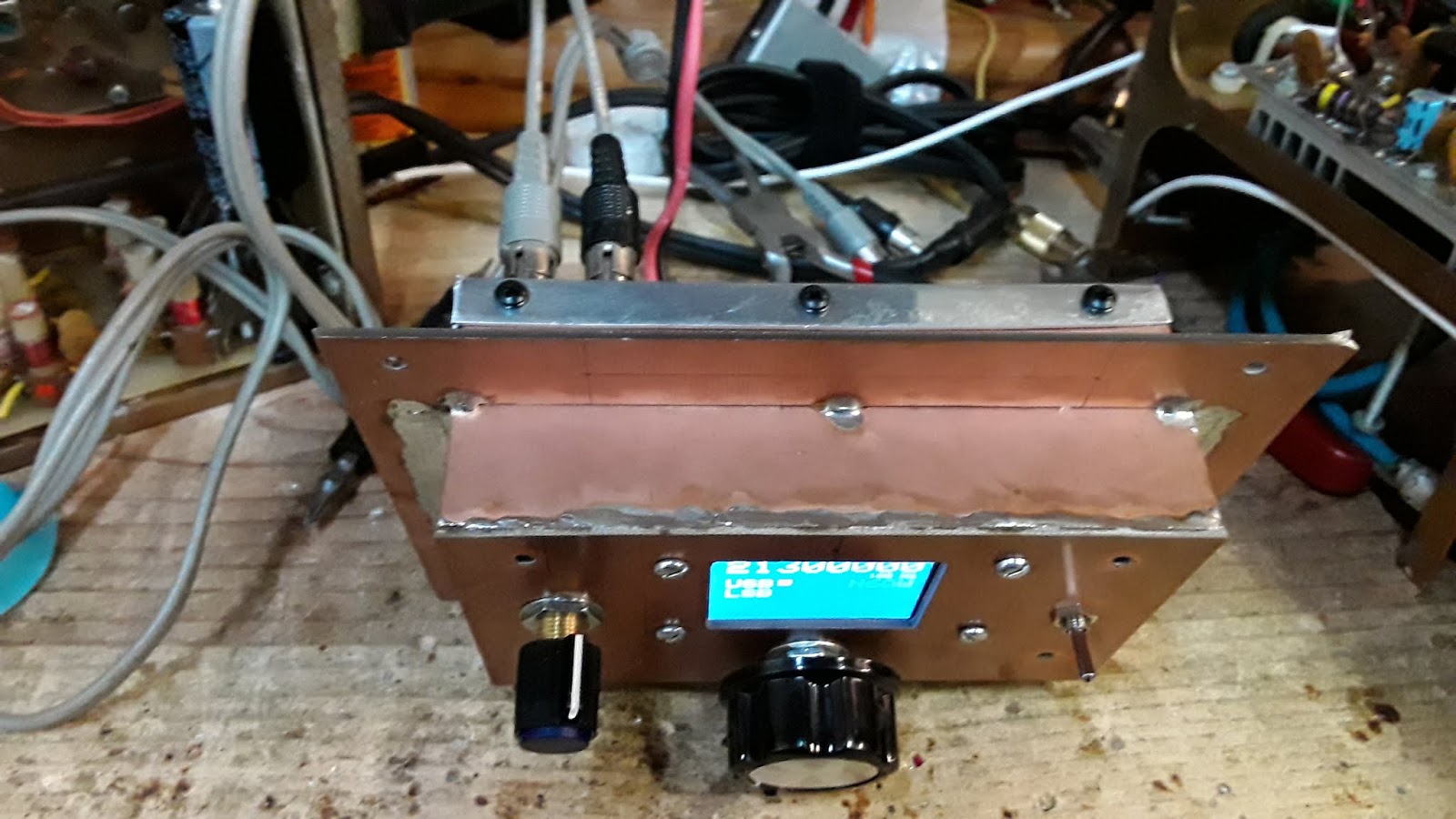
This box was fabricated from double sided copper PC board with an aluminum back cover. It was fully intended to be a totally shielded enclosure and it served that purpose when initially built as a power amplifier stage for a Ten Tec Model 540 that I acquired sans the linear amp brick. This was the prototype and a second one that was built was installed in the Model 540 which I later added a Digital Display effectively making it a Model 544. So I had a spare shielded enclosure in the "junk box".

When you undertake these zany projects there are often unexpected by products and one of those was RF noise coming from the Arduino/Si5351. A click click click sound would be heard as the Arduino went through loop and further evidenced by one of the on board LED's blinking at the same click rate. My thoughts turned into a completely shielded Arduino/Si5351 to see if it could cure the problem. The next light bulb was the enclosure I built that was hiding at the bottom of the junk box. TRGHS -- it was serendipity on two accounts as the enclosure was big enough to house the components and provided a neat "front panel" and the shielding solved the "click" sound. there are no more click sounds!

Should mention that I only heard the clicking when the antenna was disconnected or the band switch was in a position unrelated to the antenna being used. I did not hear the click sound on the transmitted signal but I did know it was there on the receive side (with no antenna).

The build itself has the display, encoder, band switch and USB/LSB select in one half, while the Arduino/Si5351 plus LO, BFO and power connectors on the back panel. This is a good way to do it since any reprogramming of the Arduino entails simple removing the back panel and you have access to the USB to Serial interface. [See the photo below.]

We are about to make some final adjustments and then we will button things up.


73's
Pete N6QW
11/06/2018 ~ Election Day

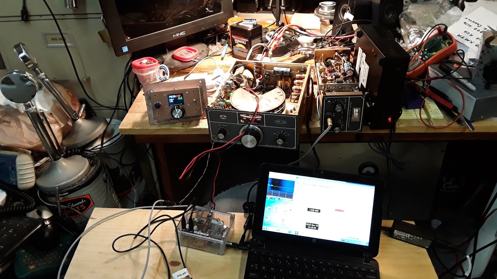
Yes I did vote (by mail) and so today I am electing to work on the Atlas RX110 and TX110. I just couldn't resist hooking up the Atlas Twins to 40M WSPR. I have a lot of data from other 40 Meter Rigs and thus can compare A to B. I am encouraged by what I see. My main concern was the transmitter, since it had problems and while I have moved forward I am still not there with the Twins where I think they can be.


Below is the hot off the press record of the Atlas TX110 on 40 Meter WSPR at 5 watts -- heard in South Africa. I was also heard in Japan.


You probably would never see an article in QST about "rebooting a Atlas RX110/TX110 with a Si5351" so you can work WSPR and as a bonus FT8. Even the Digi-Adapter is homebrew . Possibly the reason you won't see such articles is that the big commercial advertisers would not approve of hams building (or rebuilding) their own gear. This is a pure example where new technology let's the average ham to be able to work FT8 with really old boat anchors. All it takes is a bit of learning from the Internet (and blog's like this) and a desire to move out of your comfort zone. 

Then we have the new ARRL CEO wondering why the hobby is stagnant?


73's
Pete N6QW

11/3/2018 ~ See the You Tube Video of the Arduino/Si5351 Prototype Working with the Atlas Twins!


I frequently receive inquiries about building the Si5351/Arduino boards and the last blog posting was sort of a stop gap measure to answer some specific questions; but I am sure for those who don't like to read or to look at photos that was not enough. Or alternatively they don't want to invest the time to read and study. 

Note, not all Si5351 boards are a simple drop in the circuit and move on. I use the Adafruit boards or clones made by others based on the Aadfruit design. Boards are available from Hans Summers website; but he uses a different clock frequency than the Adafruit or Clone boards. Thus if you have the Summers boards you will need to make some adjustment for his clock frequency. I don't know how to do that and got lost in the process that was described to me. So if you have those boards, contact Hans Summers for any adjustments that may be required. (Possibly nothing.)

Recently I was asked about the source for the Color TFT I use in my projects. Despite having a series of webpages on the Sudden Transceiver on my www.n6qw.com website with one being specifically about the Arduino/Si5351 and a link to the supplier and a matrix of pin wiring for the several Color TFT's --I get the question where can I buy one? 

Let us start at the beginning of the current Arduino/Si5351 build. Yes there is another $100 "bought on eBay commercial radio" on the bench going through the Pete's reboot process. For about $100 I managed to purchase the "Atlas Twins" radio set which is comprised of two boxes. The first box is the RX110 Receiver which has embedded within it some of the circuitry needed to convert it to a transceiver. The RX110 is a five band SSB receiver complete with a built in AC power supply. It is a single conversion design with a 5.595 MHz six pole crystal ladder filter. As is the case with many of the economy rigs of this vintage it operates on LSB on 80/40 Meters and USB on 20/15/10. Thus only one BFO crystal is used. There are no heterodyne crystal mixing schemes! To operate on 10 Meters the VFO is running at 24 MHz and for 20 Meters it is running at 9 MHz and needless to say drift will always be a concern. [NOTE: Go to www.n6qw.com and there is a detailed link on the Atlas Twins.]

The RX110 can be operated standalone or mated with the TX110 module that now makes the unit into a complete five band transceiver. The TX110 is about 1/2 the physical size but with some slight of hand and additional mechanical hardware the two boxes are physically mated as a single unit. All interconnect wiring is done through a 12 Pin plug on the back of the RX110 and where the antenna is normally connected to the RX110 and jumper plug connects the antenna port to the TX110. The TX110 in the normal configuration is a QRP type rig with about 10 watts on 80 Meters and a lot less on 10 Meters. There was an internal add on power amplifier "brick" that would boost the output to over 100 watts on 80M and perhaps about 50 watts on 10 Meters. 

All I can say is that there was a lot of internal heat in that very small box. I say this because of my observation of the actual space in the TX110 and the fact that a prior owner hack sawed openings in the case on the bottom and top of the case where the amp board was installed. Crude is a really good word. It was obvious that my unit had the amp board but it was no longer installed. Without the amp board a jumper cable is installed so that the rig can be operated "QRP". In passing, a bit 'hokey" but there are two bands switches so at times you have to remember that both switches must be on the same band!


I don't buy things without having some specific plan for the reboot. I saw the Atlas Twins as a spring board to install the Arduino and Si5351 to enable two things: 1st is an accurate and highly stable LO generation complete with Color TFT display and 2nd to provide USB/LSB capability so that the rig could be used on the digital modes on 40 Meters. Thus why I am spending time on this post to take you through the Arduino/Si5351 sketch process and then the actual building of the hardware.

Fortunately, manuals for the RX110 and TX110 exist on the Internet and so I didn't have to guess some things. The original VFO/BFO scheme was that the VFO operated above the incoming frequency (by the amount of the BFO) for 80/40 Meters thus subtractive. For the higher bands the VFO operates below the incoming frequency (by the amount of the BFO). So on 80 Meters you have a 9 MHz range VFO and on 20 Meters a 8 MHz range VFO. One crystal BFO frequency would yield LSB on the lower bands (sideband inversion) while giving USB on the higher band (no sideband inversion). Thanks Herb.

A single three  ganged band switch on the RX110 simultaneously switches in the correct VFO coils while connecting the input and outputs of the Band Pass Filter. My initial thoughts were to "rip out" the VFO section, install a Color TFT is the frequency window and install on small toggle switch on the front panel for USB/LSB selection. Inspection of the actual hardware led me to conclude a separate small "Remote VFO" console that would house the 3rd band switch to shift the Arduino range, have the color TFT and the USB/LSB select. I might even include the Mic connector and a stereo headphone jack and even the CW key --it can do CW. This way for digital operation in my new configuration, all connections are made to the Remote VFO. I am even considering the use of a commercial sloping front panel aluminum box from Bud or Hammond. 

Long ago with a lot of help from others I decoded how to band switch an Arduino for five band operation and thus minimum  sketch development was needed. For the Atlas Twins all LO's will be above in frequency and the BFO will be switchable above and below the Crystal Center Frequency by an initial starting point of 1.5 kHz. The RX110/TX110 Manual describes the setting of the BFO by visually observing the power output at 1000 Hz and then 300 hertz. A drop of a specific level between these frequencies is the BFO set point without identifying the actual frequency. This may require several runs to get it right but we will be in the ball park perhaps not in the exact seat on our initial attempt. So we have the sketch and now to the hardware.

Having a standard layout for the Arduino/Si5351 makes for rapid prototyping and minimizes the footprint. The last blog post talked about using the Nano as that offered the most bang for the buck. Recently I bought a three pack and the cost was $4 each ($12) so that is very cost effective. Thus I will use the Nano and the Adafruit board without connectors. Connections to my standard Board are made using Pin Header Sockets and Connectors. A total of 20 connections are made to the board as follows:


  • Four pins are used for the Encoder and Step button
  • One pin (to Ground)  is used for USB/LSB Select
  • Seven Pins are used for the Color TFT Interconnect
  • Six Pins are used for the five position Band Switch
  • Two pins are used for the Source 12 VDC Input


The below photo shows how using #30 bare tinned wire that I wire from the Arduino socket to the 30 pin header (15 each side). Then wiring is taken from the pin headers to the header sockets as shown in the photo above this one. Thus I have two forms of access to the Arduino with one being the pin headers which fit standard jumper plug wiring and the second the header sockets. I can't tell you the number of times I wanted to see what is happening on an Arduino pin and posing about on the top of the Arduino board you risk shorting something out. Thus I can safely insert a jumper wore and measure to my hearts content. Two bolts/nuts secure the Si5351 to the perforated board and I will wire wrap the connection to this board. At this point the signals are digital not RF!


As I add more of the wiring I will add shots to this blog post.


Yes Virginia another transceiver in the works only this time a reboot of the Atlas Twins. In summary the plan is to leave the internal VFO/BFO intact but disconnected and all operations will be done with the Remote VFO. This modification could be noted for other Atlas owners (Models 180, 210, 210X, 215) where you can have a Digital VFO with a Color TFT display.

I have had the Atlas Twins on the air using the stock VFO/BFO and have made about a half dozen contacts with most on 40M and one on 15 Meters. The TX110 needs some work to get the power out up to spec. But I was surprised at the stability of the Analog VFO. The main Analog VFO issue is the actual readout (too macro) and of course there is a bit of a drift. It would be a near impossibility to set WSPR frequencies with the analog VFO!

73's
Pete N6QW … Stay Tuned for more innovation and creative thinking. You are learning from the Master!

The Risk of Power.

 What happens when the faithful lose faith? We don't know the result but now it is time to pop more popcorn as the interesting part of t...