Friday, June 19, 2020

New Technology for 2020 ~ Software Defined Radios for Field Day

Preparing for Field Day ~2020

June 27, 2020 ~ FD is Here!


We had an amazing FD with six total contacts including one on FT-8. I know you are snickering; but that is the most contacts I have ever made on any FD in the last 61 years!

I spent my whole allotted hour for the operation with 25 minutes wasted on my tripod Vertical antenna. It just wasn't hearing anything so I simply tapped into my 40M Delta Loop and then the spectrum lit up. Thus that is six contacts in about 35 minutes. As I always say -- the antenna is more important than the rig. More proof of that today.

But there were some proof of concept pieces to my FD (Fun Day) foray. First and foremost I now have a way to totally power my RADIG from 12 VDC including the RPi3 and the 7" HDMI. Secondly I forced myself to permanently mount the RADIG on a metal plate versus the haphazard bread board. So those were two very positive outcomes resulting from FD.

Thirdly if I would really want to operate portable say from an outdoor park picnic table using my designer mask and the RADIG as a chick magnet, then a better portable antenna would be necessary. An End Fed Wire (EFW) would be a likely candidate.

I may take another run at operating from the back yard, other than some contest weekend. This also means rethinking how everything is packaged so it can be deployed and removed quickly. Some sort of portable cart with added built-ins would seem to make sense. Need to noodle on that a bit more.

This was a fun day (FD) but most likely would not operate Field Day (FD) again. 

73's
Pete N6QW

*****


June 26, 2020 ~ The New Power Supply has arrived -- The RPI3 and the HDMI now being powered off of 12VDC!



Wonders never cease as my power supply arrived today! For the power cables to the RPi3 and the HDMI, I took two 3 feet long USB to MicroUSB cables and cut off the USB end which then was connected to the Mean Well SD 25A-5 DC to DC Convertor which has an adjustable output. A setting of 5.3 VDC make all hardware connected to the buss act like happy campers. 

Can't wait until tomorrow.

73's
Pete N6QW


June 25, 2020 ~ Final Actions for FD

Well I ordered the alternate variable 5 VDC DC to DC Convertor supply and got a shipped notice -- 4 days from San Francisco to Newbury Park a total distance of 340 miles. I have made that round trip in one 12 hour driving stint. But it takes 4 days using the USPS. Bottom line: It won't be here for FD so will have to use AC power for the RPi3.

I intend to run 100 watts with the SDR driving a small linear amplifier that formerly was the output brick for the Atlas 210X. It is compact and has the CCI LPF for just one band --40M.

Have been thinking about "snack food" -- you can't have a FD "op" without the usual snacks. I am thinking about some homebrew stuff; but haven't made the final decision. This is laughable as I only intend to operate for 1 hour; but snack food is one of the pre-requisites. 

Oh best check the ARRL rules on how I class myself. It will be single operator, single rig but AC power (darn) and definitely not wimpy QRP! Also need to check start times and duration. I will only be operating SSB (are there other modes?)

Set the portable antenna up yesterday after the lawn service finished, as I didn't want to have my ground plane caught up in their mowers. ( BTW Jose, Peppi and Luis do an outstanding job and indeed I am lucky to have these three individuals care for my yard. Always reliable and super careful it is so nice to see service providers who make a difference.)

I hope to add some detailed snaps of my portable antenna (later today) as that may be of some interest how I did it.


Stay tuned to this space. Oh very likely I will use my GoPro to film part of the FD op and so it will be available on you tube.

73's
Pete N6QW


June 23, 2020 ~ FD Power Supply

The SDR RADIG With the Raspberry Pi3 and the 7" HDMI now totally on 12 VDC!     But There is a problem!

My goal was to have my FD station operate from 12VDC. I was able to power up everything from 12 VDC and then I noticed a small lightning bolt appear on the screen. 

That tells me there is low source voltage (not current) and sure enough the voltage was only 4.97 VDC. The Pi is especially susceptible to having low voltage input and anything less than 5 VDC makes it have heartburn. 

Unfortunately there is no output voltage adjust for this module. I will have to investigate further if t can operate this way (doubtful since the power on LED flickers on/off). Back to the Mean Well catalog. I think the HDMI can live with the lower source voltage but not the Pi3. Stay tuned.

Found a suitable supply. Same 9 to 18 VDC input but the output can be varied from 4.9 to 5.5 VDC and is rated at 5 Amps. It is the Mean Well SD25A-5 and is $22 from Jameco Electronics. That will cure the problem and It looks like with a Micro USB to USB C adapter it will work with the RPi4. So a bonus. 


I find there is an increase readership to the blog when I present techie stuff rather than trying to raise our social consciousness level. So Some Techie Stuff today.

The Problem: My RADIG which is the rig of choice for field day has some rather unusual power requirements. This is further compounded if you would want to take the RADIG portable or operate off grid. So lets us start first be examining the several required power sources requirements.

The RADIG has a built in fully functional computer and we have a choice of either a Raspberry Pi3 or and ASUS Tinker Board. These SBC's (Single Board Computer) require 5 VDC at typically 2.5 to 3 amps. Both have WiFi so if you are near a hotspot you can watch Netflix or You Tube while not on the air.

Next is the 7 Inch HDMI display which needs 5 VDC at about an amp for the backlit display. 

The radio part itself operates from 12 VDC with about a 400 ma draw on receive and up to 2 amps on transmit ( we get about 6 watts PEP).

If we drag along a 50 watt "leeneair" amp then we need about 12 VDC at about 10 amps. Man how that current adds up quickly. Of course we could do QRP (but that is like a trike with training wheels).

The 5 VDC requirement can be addressed using some very excellent DC to DC Converters from Mean Well. I have used these in other projects (such as the 2nd ZL2CTM transceiver) and NOISE is not an issue. These converters take in a voltage from 9 to 18 VDC and produce a consistent 5 VDC. This is great like when your main battery voltage starts to drop down to 11 VDC. 


See the nameplate for the Model Number and these supplies were Purchased from Jameco Electronics in San Francisco. They are on the web. The supplies are roughly 2 Inches square by about 1/4 inch high.

The RPi3 (or Tinker Board) are powered through a Micro USB cable. The same applies for the 7" HDMI. The RPi4 needs a USB "C" power connector.  So the plan is to use two USB to Micro USB cables and simply remove the standard USB end and that forms the connection to the 5 VDC side of the Mean Well. The primary side of the converters will be switched so you could actually turn off the 7" HDMI display to conserve power. 

For my application on Saturday I have a Astron 7 Amp Linear DC power supply and that will furnish power for the converters as well as the main power for the RADIG SDR. It will be close; but I will run some tests ahead of field day. Funny I have a Samlex 22 amp supply that is smaller and lighter than the Astron and I might just press on and use that supply. 

Later today I will add some construction photos of the SDR RADIG "power pack".

Pete N6QW


June 22, 2020 ~ Is my Coax Cut?

Is it me or have conditions been marginal? At least they appeared so over the weekend at my QTH. I have a metric that lets me judge the state of the band.

There is a daily "old coot" net somewhere in Arizona whose sole purpose is to complain about their many medical issues. We have gout, ingrown toenails and bit of prostrate trouble mixed in with COPD. Then of course there are bouts with flatulence. 

The metric --how strong or weak they are is telling about band conditions. Usually the lead station is typically in the S5/6 range. If he is in the noise then I know the band stinks. He was mostly in the noise this past weekend.

Hopefully we will have great band conditions coming up this next weekend for Field Day.

Got treated pretty well for Father's day including one special homebrew gift from my daughter. 

For 17 season's now I religiously watch the US Navy Cop Series entitled NCIS. When I was in the US Navy, I frequently worked with the NIS as it was called then. In fact they tried to recruit me as an agent when my service commitment was up. Carrying a gun everyday as I did when I was in South Vietnam didn't seem like a good path for me.

My daughter is likewise hooked on the series and the hero, Gibbs, played by Mark Harmon has a series of guiding principles called Gibbs' Rules. She went about imprinting Gibbs' rules on a T Shirt for my gift. Example Rule #51 Sometimes you are wrong. 

For those who attended the emperor's (with a small e)  fiasco in Tulsa this past weekend -- Rule #51 applies and regrettably if you do the math based on the ratio of US deaths to those infected and then apply the trickle down multiplier effect to 50% of those who attended (typically a 1:12 Ratio) you have 36000 infections and the number of deaths could reach 2000 just from attending the emperor's cluster bang! 

In about two weeks hope all those folks who get sick really thought it was great to attend, to not wear masks and to sit in some stranger's lap. The emperor doesn't care about you --he just wants four more years to be emperor!

Pete N6QW

*********


June 20, 2020 ~ Checking SWR.

I replaced the 40M Hustler whip with a straight section of antenna so that I am loading an elevated whip 9 feet long. I added three 1/4 wavelength radials and used my homebrew tuner to bring the SWR down.


To make the SWR measurements I used a homebrew dual band (40/20M) SSB transceiver that will run 15 watts output.

The jump to 40 Meters was a pretty easy match where I got 1:1 and the background noise was loud. The 20M settings are yet to be determined.


********


I hope to participate in this years Field Day entirely from my small Southern California postage stamp back yard. There is a long history of my disdain for the yearly weekend long organized mayhem that afflicts our ham bands. This event, of course, is sponsored by one of the USA national amateur radio organizations. Thus my participation appears counter to that long held belief. Well actually not!

My interest is operating for at least one hour in the Field Day "clusterbang" and based solely to prove the viability of my entirely homebrew rig and antenna. 

Over the last week I have dug out quite a few of my commercial treasures such as the Collins KWM-2,  the SBE-33,  the Ten Tec Omni C and even the Galaxy V to evaluate their use. Then it struck me these older commercial rigs simply are not as good as the SDR Rigs I have built. Now that is a profound position to stake out!

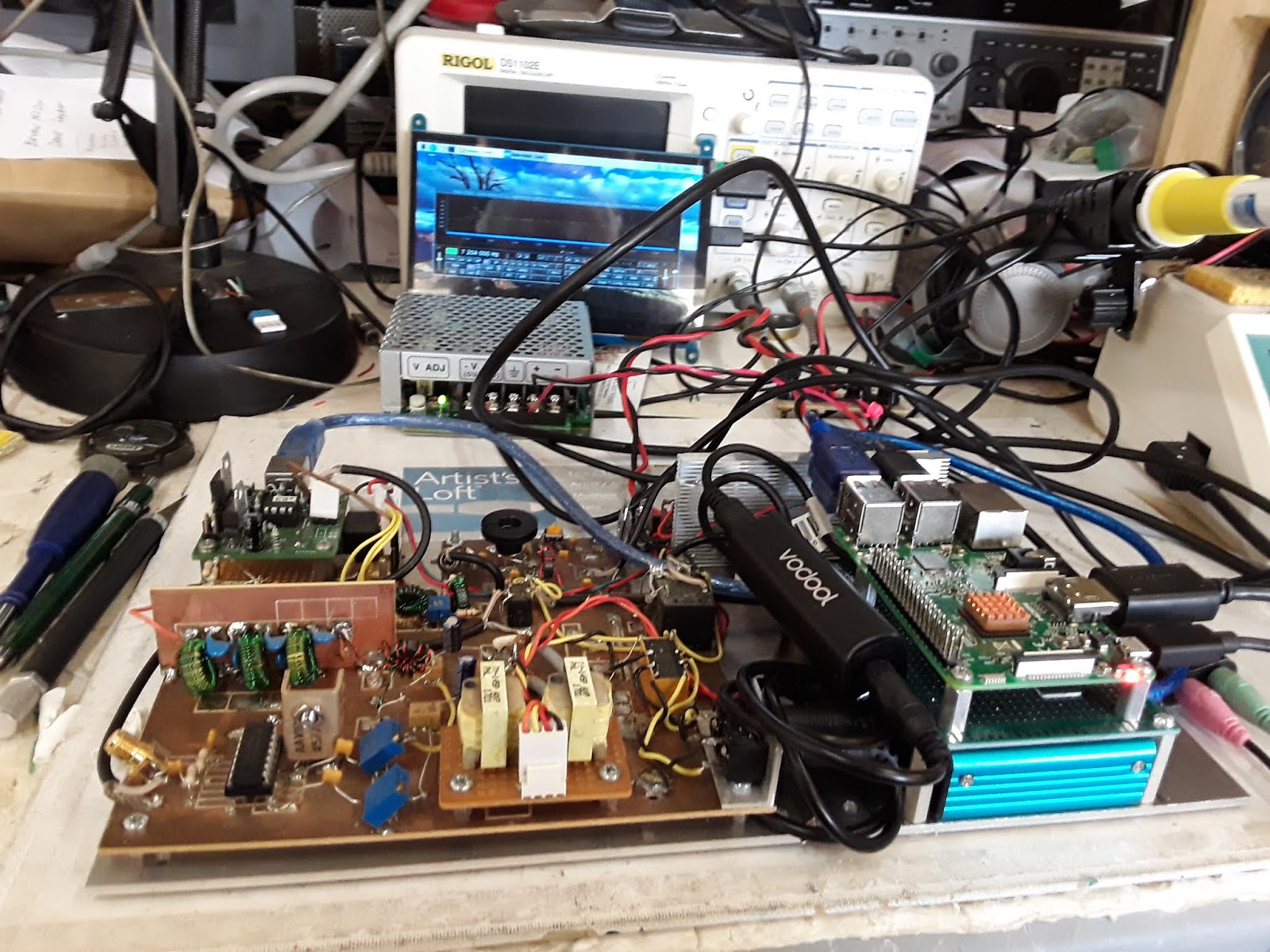
Today I took the RADIG that was mounted haphazardly on a wooden board and integrated all of the boards and RPi3 on a metal plate. Nice! A compact RADIG. It was purely accidental that it all fit on the metal plate. Now I need to work on the power supply board where 12 VDC will power everything!


This was the RADIG before I installed it all on a metal plate. This will be the Field Day Rig.


My RADIG running off of the Raspberry Pi3 and Quisk gives me many of the functional features found in many of the current medium to expensive commercial SDR rigs --at a fraction of the cost. I have the waterfall, filter options, split operation and one of the most important --frequency accuracy and stability. I know that my RADIG is accurate to within 10 Hertz!

[A ham running a FLEX6700 with a GPS Synchronized Rubidium Frequency Standard scolded me that I should get on his frequency as I was 10 Hz off -- thus my claim!]

Thus I hope to share on this blog the details of the station I will be using. Firstly I will only operate on 40 Meters and possibly the source will be 12VDC as I likely will utilize the two 12 VDC to 5VDC DC to DC Converters (3 amps a piece) to run the Pi3 and the 7" HDMI Screen. That is another driver --getting everything to operate from 12 VDC. 

Today I am finalizing my whip antenna install as that will be the principal antenna. One of the original premises for Field Day was to prove the viability of hams to provide emergency communications during a disaster.

Now the focus is to showcase the latest megabuck commercial rigs that are promoted by the national ham organization. I guess the theory is --unless it is an ICOM 7300 or a YASEU FTdx101D then it is impossible to provide emergency communications. 

Let's all rise up and as Jack Black would say in the seminal movie "School of Rock" and stick it to the man and do it with homebrew gear!

73's
Pete N6QW

We should also stick to the emperor (with a miniscule e) come 137 days from now. 

Friday, June 12, 2020

New Technology for 2020 ~ The Homebrew DDC SDR Transceiver

Yes! That is what I said.

"A Homebrew DDC SDR Transceiver"

June 13th, 2020 ~ I have had a response to my inquiry.


Yes indeed there are readers of this blog who are "doing the DDC" thing and I even have some recommendations on different LTC ADC's (perhaps less expensive). 

I will share that model number and a spec sheet later today. This could get really interesting.

The Model # is the LTC2291 @ about $28 from Digi-Key. Still not under $10.

No Op-Amps, Precision Capacitors or Resistors will be involved with this project.

73's
Pete N6QW

*****


Last evening I had an opportunity via Zoom to share some of my homebrew projects with the Cedar Valley ARC located in Cedar Rapids Iowa. What a great bunch of hams -- many are former and current Collins Radio Employees (now a unit of Raytheon).

I was asked quite a few questions: but a couple members pointed a finger at me asking why I was using the front end analog hardware in the three SDR transceivers I built. The burning question how come you are not using DDC? My response was a sort of mumbled, well you really need a board for that as most of the devices are the 48 pin square (looks like SMD) device. So that got me thinking: Pete why aren't you doing that?

A little research turned up a candidate device from Analog Devices (actually Linear Technology a subsidiary --you know the LT Spice guys) called the LT2165. It is a UHF capable ADC and has some interesting specifications ( a lot that escape me). It also has a hefty $82 price tag. No wonder they get $6K for a FLEX6700.


Anyway this posting today is to inquire if anyone is working on a DDC SDR transceiver and secondly about the device itself (anything faster, better, cheaper as a candidate)?

It appears you have a choice of all sorts of outputs and so then the next big question is how you convert those outputs to something useable like modes, waterfalls, spectrum display, band changing etc.

So this may be the latest project for me. I foresee this as much more fruitful and productive effort versus trying to get opposite sideband suppression out of a mystical 6 pole op-amp phase shift network that even when the planets are aligned is maybe 45 dB. 

Stay tuned to this space for the next great adventure.


73's
Pete N6QW

Thursday, June 4, 2020

New Technology for 2020 ~ A Second ZL2CTM SDR Radio

When You Know Stuff, You Can Do Stuff! All In A Days Work!

June 12th, 2020 ~ WSPR Data for the New 40M Loop Antenna

Tabular Data for Transmit at www.n6qw.com

Most stations that heard me at 500 milliwatts  are close in; but N6QW was heard in New Zealand. Received stations were from Japan, Australia and many across the USA for about a two hour period.

Two days is just that --  two days. 


No Op-Amps, Precision Capacitors or Resistors were used for this evaluation.

73's
Pete N6QW


June 11, 2020 ~ 1:2 Magic Balun Info


With thanks to Lars we now have info on how to build that 1:2 Balun. It is like a head slap moment one you see the pictorial. Initially I had seen just a photo of the completed balun which used the same color wire for both windings -- it was hard to tell the actual number of turns and what connected to where. The color coded wire makes everything lucid! The 1:2 matches 50 Ohms Unbalanced to 100 Ohms Balanced --This will also work for other antennas aside from Delta Loops.

Ran some preliminary WSPR tests with the new antenna on 40 Meters and was heard in Australia running only 500 milliwatts. So that is a good sign but only one day of observation. I will continue to collect data and provide hard statistics on the antenna based on a period of many days of observation versus just a single snap shot in time. 

Since there will be much data I will most likely post the results on www.n6qw.com. Accordingly I will post info on this blog when I have posted the results on the website.

No Op-Amps, Precision Capacitors and/or Resistors were used for the evaluation. 

73's
Pete N6QW


********


June 10th, 2020 ~ New Antenna + SDR

So late yesterday I had the new antenna configuration in place and connected to the ZL2CTM SDR Rig. 

Now the burning questions: Were there angelic voices being heard gently singing in the ether, Were there rock crushing 40dB/S9 signals being heard coming out of the speaker, Did the whole SDR rig take on the aura of Juliano Blue, Was the SDR Rig being driven into saturation from  so many strong signals, Did it seem my station was on par with the $20K ICOM IC7851? OK Back to earth!

I made several contacts with the new lash up and the received signals were strong and my reports were like wise in the S9+ category running only 100 watts. But hey dude, this is like saying a Six Pole Op-Amp phasing network has 70 dB opposite sideband suppression (like I was told by one ham).

We need to have some real data on performance and that data should be over a sufficient sampling period so as to look at the average of band conditions. From this data then one could make cogent and reasoned pronouncements on performance. The perfect tool when you have no fancy spectrum analyzers or costly test equipment is to use WSPR.

I plan on using 40M WSPR to look at both the received signals being heard as well as my transmitted signal at 0.5 watts. I happen to have data from prior WSPR runs using the older antenna configuration and will use the same transceiver that was used on those prior runs. Thus the variables are reduced to a few such as the new Antenna itself and band conditions. Now if you sample over a long enough period then hopefully we will arrive at average band conditions. 

The selection of 0.5 watts of power output will provide a baseline that says --for this low a power level the antenna performs thusly -- at 500 watts --it only gets better. (That is a 1000 times increase in power.)  I will also have a chance to see the area of coverage and has that changed since I did have to shift the broadside direction a bit to fit on my lot. 

I will share my results as I develop the data base.


Needless to say no Op-Amps and or Precision Capacitors or Resistors will be used for this evaluation. 

73's
Pete N6QW


*******


June 9th, 2020 (Late Afternoon) More Antennas!

Daily I take the XYL to a local Mall which is still closed along with a sack lunch and we just park in an abandoned lot and have lunch. Afterward she gets to walk around without concern for social distancing or having to wear a mask. It is outdoors and no one around! So this is good.

Today while we were  sitting in the car eating our sack lunch it was like a lightning bolt hit me! I already had the makings of a Delta Loop that would enable me to experiment before I committed to buying hardware and homebrewing a complete metal antenna. True it would be fixed in one direction but by making it for 40 Meters it will also work on 20 Meters.

So here is the idea. My 40 Meter antenna is 98 feet long so it would look like 3/2 wavelengths on 20 Meters. That was the starting place.

Now in looking at the Single loop Delta Loop the formula is 1005/Frequency. Thus for 7.2 MHz we are just shy of 140 feet. The two legs are 49 feet each and so a piece to connect the two ends would be 42 feet. All I had to do was find a piece of wire that after connection was 42 feet long. So for 20 Meters this is a 2 wavelength long loop antenna! That has got to mean something!

I have a wide range tuner and sure enough I was able to get a good match for 40 Meters and 20 Meters as well. Later tonight I can see how the East Coast is coming through on 40M as that is the broadside direction.


One area of tinkering will be the Balun. Right now I have the 9:1 in there and when the cores come I can try winding some different ratios to see what works best. If this 40M antenna conversion works, all I can say I have been asleep at the switch these last 5 years.

This will be a good test bed to see if I proceed with the metal version. The current arrangement has about a 45 Degree tilt to it, so I don't know how that will hurt or help.

Pete N6QW


June 9th, 2020 ~ Antenna Stuff

For those of you who regularly listen to the Solder Smoke Podcast, specifically SS#222, I mentioned this might be a great time to work on antennas.

Several years ago I undertook the installation of a two element Mosley Tri-Band Beam. The technical aspects of the installation have worked out well. My install has weathered several years of some fairly significant wind storms and the beam stands tall and has not fallen down.

The problem -- the beam itself is intermittent and I hardly got a year of service before it started acting up.  It will load and then the SWR goes to hell and the received signal drops off the face of the earth. 

A contact with the manufacturer was not very fruitful. The beam will take legal limit which I never ran and so the probability of a blown or intermittent trap is less likely. This was affirmed also by Mosely. One possibility was that  there was a latent defect in the traps at install. The coax could be an issue and I have a new piece ready to install; but the pesky secondary problem -- I don't do roofs or climbing and getting someone to take down the beam is problematic as the Covid19 is still rampant in California.

I tried to noodle my way through a repair of the beam. So you take it down and evaluate the first easy possibility -- bad coax and get it hoisted back and perhaps the problem is still there which requires a trap replacement. That adventure for the traps is $150 and not counting the labor for down, up and maybe back down. 

I really only want a directional antenna with some gain for 20 Meters and that opens up spending my limited cash on a new antenna that would cover just 20 Meters. 

There is a company (SAL) that makes a 20 Meter Moxon (all metal) and that cost is $400. I could buy a single band Spider Beam -- more than $400. Or I could write K3LR a check for $600 for a 20M single band Hex Beam or send him $300 for a EA Delta Loop.

The Delta Loop has less gain than the other beams but offers possibilities for me to homebrew an all metal version for less than $300 that DX Engineering charges. Thus I have been doing research on Delta Loops.

This is where blog readers come in... I am looking for the following info.

  1. Anyone have a Delta Loop and your experience with this antenna?
  2. Anyone homebrew a Delta Loop?
  3. For 20 Meters it looks like using the formula 1005/(Operating Frequency), that about 70+ feet of antenna is required with a 1/3 wavelength in each leg
  4. There are many configurations for arranging and feeding the Delta Loop and my approach would be to have the equilateral inverted triangle with the feed at the bottom. Anyone have this configuration?
  5. The input impedance is around 100 Ohms (balanced) and there are several methods shown for matching including a quarter wave matching section of 75 Ohm coax and another using a 1:2 Balun where 50 Ohms unbalanced is matched to 100 Ohms balanced. 
  6. Now this is where the 1:2 Balun's shown on the Internet and you tube videos are much like saying she has "big boobs" which is described as anything from a cup size 30A  to a whopping 44DD. There is much creditable info on 1:1 4:1 and 9:1 Baluns --but the 1:2 is a gaping hole. There are some commercial companies selling 1:2 Baluns which typically have a price point of $100. I have a FT240-43 core coming ($14) and I already have a spool of #16 enameled wire. The piece de resistance is a HD plastic electrical outlet box which is about $4 at Home Depot. 
  7. To date I have not seen a cogent electrical schematic of the 1:2 Balun as to number of turns/connections. Additionally photos of homebrew 1:2 units are all over the map (like the gal with big boobs). So if anyone has a reliable schematic  sharing of same would be appreciated.
  8. This past week there have been some good openings on 20Meters so there is an incentive to get cracking. 
  9. No Op-Amps or precision capacitors or resistors would be involved with the build of the homebrew Delta Loop.

73's

Pete N6QW


***********
June 8th, 2020 ~Alert! Alert! Alert!

I received an email today that sort of knocked me off my feet and thought I would share this interesting situation with the blog readers.


Some of the blog readers might be members of QRPARCI and thus receive the publication QRP Quarterly. At one time I belonged to QRPARCI and contributed many articles to that publication. 

In 2013 at the suggestion of one of the editors I actually designed a 30M CW Transceiver and built the unit which then was formally published in QQ at that time. As you well know I hardly ever operate CW; but this rig had some nice features like RIT. 

That rig has since been canabalized and the modules are now resident in at least a half dozen SSB Transceivers. I never did see much interest in that project from the readership and I was not put out because of a lack of reader feedback. This was so unlike the LBS project!

So today's email... I was advised that the latest QRP Quarterly Issue contains that same article that was published nearly 7 years ago. I must claim ignorance as I was not made aware that it would be republished and never contacted about that possibility. 

Since I was never compensated for any article I produced or reimbursed for all the parts used, that leaves a question in my mind about who really owns the article. Maybe some of you lawyers out there have the answer.

So if anyone has a question about the article --don't contact me as I no longer have the actual hardware in its original form and that was a long time ago. You know I had a bad feeling at the time about that project and now here it is like Freddie Kreuger. 

If you have any questions on the 30M CW Transceiver as it appears in the current QQ, contact the QRP Quarterly Technical Editor not me. Regrettably my name is on the By Line; but I cannot vouch for what was republished as being accurate. 


73's
Pete N6QW


*****************


June 7th, 2020 ~ A Hardware Tour!


On the Air QSO ...


June  6th, 2020

Yesterday as I looked at the second build of the ZL2CTM SDR Transceiver, I realized I had successfully anchored down all of the boards on two metals plates; but had a structural problem. The issue -- how to make it an integral assembly. There was no easy way to mechanically assemble (connect) the two metal plates.

Then I remembered that about two years ago I bought a large aluminum chassis to house the original RADIG SDR Transceiver. I did not proceed with that plan as it would have involved a lot of metal bashing. Now the problem where did I put it for safe keeping? I found it. A preview...

( This photo has the Mic Input and Audio Gain Control Swapped for better ergonomics)

This is when the value of experience comes into play. The Plan: I carefully removed all of the boards from the two metal plates and used those metal plates plus the front sub-panel as drilling templates for metal bashing the aluminum chassis. The chassis size is 12X8X3.

Firstly I used heavy duty tape (Gorilla Tape) to tape the drilling templates to the metal chassis. This is where you measure twice and cut once. You have to keep straight that the template must be the mirror image side that you drill through. It took only about 15 minutes to drill the chassis through the two plates. Also a caution about clearances and centering to allow room to work on the various boards once installed. 

One particular assembly has a clearance problem. For those who use magnifying glasses to pick over my work, you will see a black rectangular box assembly that is fitted with two 3.5 MM stereo jacks. (Left side of chassis looking from above.) 

This assembly is sold by PJRC (Teensy supplier) for the purpose of isolating the audio ground from the system ground. Without this device --the SDR suffers from a high pitched whine. There is a short cable to connect this box to the Teensy CODEC board and the connectors are straight in so that is the clearance problem.

Normally with flat stock I can use my CNC mill to cut the rectangular hole for the LCD. Not easy to do with an aluminum chassis. So after outlining the size of the hole on the front panel  first with a pencil then with Gorilla Tape, I drilled out the LCD panel space  using a series of holes that were aligned slightly smaller than the actual cut out. The final holes size was carefully filed with a series of files. Initially I used a rough file and the finish filing was done with a Jeweler's File. 

With all of the boards already wired  and aided by the cable ties (good idea Pete) I was able to simply drop the boards into the inside of the chassis and bolted everything back up. I used 4-40 nuts and bolts with liberal amounts of star washers so there would be a "tight" connection between the copper boards and the metal chassis. 

The IRF510 assembly, Low Pass Filter and TR Relay were simply bolted in place on the back panel. The bonus of course is the whole chassis is the IRF510 Heat sink! The final wiring involved connecting to the IRF510 Board, the TR Relay and the External Amplifier control circuit (Who in their right mind runs QRP?) 

Luckily where the TR Relay is located and where there is the interconnect to the receiver circuitry is but a short 2 inches --now that was pure luck -- but made things "Tight and Tidy".

A short piece on wiring --- I use Yellow wire for anything transmit and Orange wire for anything receive. This project uses a relatively small number of boards so not as difficult as one with more boards --but having the color coded wires sure makes things easier to trace and troubleshoot. Wiring that has power applied at all times is Red.

There is a switching power supply installed on a piece of perf board right behind the LCD. This is a 9 to 18 VDC IN to 5 VDC OUT used to power the Teensy 3.5, CODEC Board and the Si5351. This was to isolate this critical part of the circuitry from the rest of the rig. This little switcher is good for 2 amps and is made by Mean Well. I heartily recommend using this supply for application to this critical circuitry. 

The blank panel space on the right hand side will eventually have a panel mounted speaker installed and there is a plan afoot to swap the locations of the microphone input jack with the audio volume control. The two controls used the most are Tuning and Volume. It makes sense to have them grouped close at hand. 

BTW I have two additional switcher units good for 3 Amps a piece -- and there is a plan to take the original RADIG with the Raspberry Pi3 and 7" inch HDMI and run the RADIG completely off of 12 VDC as a portable rig. 


Please note: No Op-Amps, and/or Close Tolerance Capacitors and Resistors were used for this project. 


The total elapsed time to convert from the prior assembly to the chassis form was about 5 hours. The work was greatly aided by having in addition to a CNC mill a Manual Mill. When you have the right tools a lot can get done.


I hope to use this Rig on the CPAC Contest today. 

Finally --WYKSYCDS.

73's
Pete N6QW


***********************

Forget that Phasing Stuff. Real Radios use Microcontrollers or Computers! 

No Fake Claims about Opposite Sideband Suppression. No Op-Amps! No Fiddly Circuits. No Expensive Capacitors. This one works!

Note the aluminum bottom plate to collect all of the circuit boards and the liberal use of "pink" cable ties, Five watts of pure joy and another opportunity to use my can of Juliano Blue Spray Paint. (Including my hands when the can accidentally misfired)

Now this rig makes sense and is a dream to operate. No reports about the other sideband. How quaint! 

I am skeptical that all the glowing reports about phasing rigs  I received are in fact true. Basta!

CPAC Contest this weekend -- good opportunity to use the new rig.

Pete N6QW


The Risk of Power.

 What happens when the faithful lose faith? We don't know the result but now it is time to pop more popcorn as the interesting part of t...