The Simpleceiver Direct Conversion Build is Working ~ Houston We Have Ignition!
We now have the J310 "Dual Gate MOSFET" Product Detector working as a 40M Direct Conversion Receiver! All of the upfront analysis we prepared has paid off in big dividends. The test configuration consists on the J310's as the Product Detector, an Arduino Pro-Mini driving an AD9850 in the range 7 to 7.3 MHz supplying the LO signal and the audio amplifier is the NE5534 driving an LM-380 . There is no additional amplification nor Band Pass Filter in line at this time. There is a short video to show "proof of life".
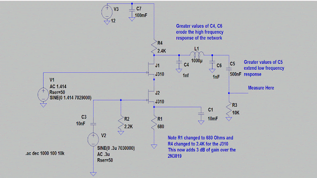
Our basic J310 "Dual Gate MOSFET" schematic was used as shown below. There are but two additions: 1) A 3 turn primary to 20 turn secondary wound on a FT-37-43 core (#26 wire) is used to match the 50 Ohms on the antenna connected to Gate 1 (J2), where the match is forced to 2.2K. C3 is not used with the matching transformer. This is a 44:1 match and 2) A 10 NF is connected to Gate 2 (J1) and the other end is connected to the AD9850 DDS.
This circuit forms the basic Dual Gate MOSFET template that will be used throughout the total Transreceiver project. With some slight changes this circuit will morph into a RF amplifier that can be used on either the receive or transmit side. More on this in a later post. By the Way in the above configuration this Product Detector is good for 18 dB gain. Run the LT Spice if you are not convinced or you could just look at Part 7.
Below is the schematic of the Audio Amplifier stage consisting of the NE5534 and the LM-380 --good for two watts. The LM-380 is used in many commercial transceivers and should allay the fears of those who pan the LM386. [Yes to the question-- this is a GIF --still don't understand why jpgs are no good.]
This is the test set up with Pro-Mini/AD9850, the Product Detector and the NE5534/LM380
The Arduino software I am using is based on the code from AD7C. The Microcontroller is the Arduino Pro-Min and for driving the AD9850 I am using pins 4,5,6 and 7. You must use Pins 2 & 3 for the encoder interrupt, Pin A3 is used for the step increment. The LCD is a 16X2 with a blue background.
Stay Tuned --let the fun begin.
73's
Pete N6QW


