Thursday, May 5, 2016

A New SSB Transceiver from N6QW

A New SSB Transceiver from N6QW

 
Several years ago I prepared and published an article on a 30M CW transceiver. I designed the radio (it even had RIT) , built and tested the radio, wrote the article and quickly placed it the storage locker. I am not a CW fan even though I did take and pass the real Extra exam when you had to copy 20 WPM. I much prefer SSB and so this project is the best of many worlds.
 
Parts of the 30M CW transceiver have found their way into the ZIA, 20M SSB transceiver and now the mainboard has been reworked to emerge as a 40M SSB transceiver. Some of that effort was to build and install a 6 pole, 5 MHz Crystal Filter and to build an external BFO which will be used to feed the NE602 Product Detector on receive and an SBL-1 Balanced Modulator on transmit.
 
The original 30M CW transceiver had a varactor tuned VFO but the new rig has the Si5351 that will supply only the LO signal. The display of course is the 128X128 Color TFT. I am amazed at how many 128x128 TFT's displays are showing up world wide using code that was developed by me for the Belthorn III; but also is used in the LBS II. This will make the 3rd application. Similar code was used on the ZIA but that has the Nokia with a black and white display.
 
The goal is to have it operate only on 40M LSB and  have a power output of 5 watts. Below is a sneak peek at the new rig al fresco on the work bench. I still need to add the transmit chain and power amp plus the microphone amp which will be SMD. A couple of more days should do it.
 
This is the first major soldering project in the last 5 months.


 I will update this post as I add more hardware and get the transmit chain working. For info on the original 30M CW transceiver project refer to the 2103 article that appeared in QRP Quarterly.

73's
Pete N6QW


Monday, May 2, 2016

Omnia SDR and WSPR-2

More Omnia SDR and WSPR-2


31 Flavors of WSPR

 
Having been successful at implementing the  plain old vanilla WSPR on the Omnia SDR, I thought I would investigate using what is called WSPR-2. Backing up, K1JT (Dr. Joe Taylor) has released a package of software programs that are bundled under one download and simply menu selected. This package is called WSJT-X and the version I used was 1.16 XX
 
What distinguishes this package is that there are what I call both active and passive programs contained therein. By my definition WSPR is passive -- turn it on and it listens for a set period of time and then can transmit for another period of time. Basically you can turn on WSPR, go to work and when you come home at night you can see who your WSPR rig spotted and who heard your WSPR signal. You just get to look at the reports but the computer had all of the fun. I would call that pretty passive.
 
The other modes in the package are like WSPR in that they can listen and record various stations BUT are different in that you can actually call CQ and contact other stations. Built in functionality includes canned scripts such as Name, QTH, Power Level and Antenna. Simply push one of the message buttons and in perfect CW, the information is spit out to the other station. I think it may be even possible to do the manual override where you can use the keyboard to type small messages. Pretty cool. These modes go by names like JT-9 and JT-65.
 
My main focus was the WSPR-2 and my desire to have that work. Thus I did not do the JT-9 or JT-765. However, I did put the software in that mode and it was copying stations using JT-9/JT-65 as I could see the information displayed on the GUI window.I guess I could have sent out a message to the message board asking how to setup WSPR-2--but I usually find the responses are not always correct and you waste a lot of time. Thus I thought if I can figure it out then I will truly know how and if I do a good job of documentation you will too.
 
The set up effort needed for the original WSPR which was described in an earlier blog post is almost identical --so that was a tremendous help to me. The VAC is used again as is the Com0Com. The HDSDR sound card set up is exactly the same as is the CAT to HDSDR. (Read the earlier post and I won't repeat everything here.) So that part is easy. The main set up changes occur in the WSPR-2 setup. Once again we call the Omnia SDR a Kenwood TS2000. Also remember that specific frequencies are used and the  Omnia SDR must be in USB
 
Once set up the normal operating screen for WSPR-2 looks like below. WSPR-2 has some additional really nice features over the original WSPR GUI and chief among these is that it tells you the distance to the station being heard. This info was not available on the version 1 WSPR and to find the real distance you had to go to the main data base. The reason I highlight this is that frequently you will be spotted by someone with an exotic call and your mind immediately jumps to the idea "you were heard by DX". Just last week I had that experience with WSPR and later found out he was about 56 miles away. Another nice feature is that there is a slider bar right on the WSPR-2 GUI that lets you adjust the power output of the Omnia SDR. It is located along the lower right hand edge of the screen marked Pwr.


Here is a shot of the screen when you use JT-9/JT-65. It is the display right below the WSPR format and transitioning to these menus is a simple click on the upper task bar menu for "MODE".
 
 
When you see a green highlight it means that station is calling "CQ". I find that when you change bands on the WSPR-2 screen -- the Omnia follows right along. So there is some real goodness here.
 
So now lets look ate the screen requiring input on WSPR-2. On the upper task bar is the File Tab. Click on that and you get a drop down menu with one entry which is entitled "Settings". Click on that setting and another menu pops up that has multiple tab selections. The 1st is marked General where I entered my call sign and grid square. There are some other selection which I mostly ignored. The 2nd Tab is marked Radio. Here is where you enter the Kenwood TS200 , the serial port pair, Com 4 (the HDSDR selection on CAT to HDSDR is Com 5), the baud selection which also matches the HDSDR choice, Data Bits are 8 and Stop Bits are 2. (This was the same on the WSPR 1 setup). PTT method is CAT (like in CAT to HDSDR). The 3rd tab is Audio and like in WSPR-1 we used VAC 1 and VAC 2. The final photo show the Radio Tab and the Soundcard Tab on HDSDR.
 
There is a caution here about power output -- I can get better than 2 watts out of my Omnia --that is not a good idea because of spurious emissions. The Omnia SDR  Spurs meet the FCC spec for a Pout of 1 watt. A word to the wise -- while the BS170's undoubtedly will provide greater than 2 watts without a self -destruction it is not wise to be spewing out spurs and distortion. Keep your signal clean!
 
73's
Pete N6QW


 Have fun -- the software and the radios themselves are simply amazing.
 
73's
Pete, N6QW

Friday, April 29, 2016

Omnia SDR on WSPR

Omnia SDR on WSPR

Putting your Omnia SDR on one of the digital modes!

 
Updated 4/30/2016-- Synchronizing your computer to Internet time.
 
 
One of the really neat features of the QRP SDR radios is the ability to couple these radios with several automated computer programs where the radio + computer get to make "QSO's" while you are off doing other things. WSPR a program developed by Nobel Laureate, Joe Taylor, K1JT is a really cool program where your rig listens for weak signals and then uses  automated reporting via the Internet to a central database. WSPR is an acronym for Weak Signal Propagation Reporting. My Omnia SDR operates on 60-20M and so that is a great mix for 24 hour operation. So far it has been used on 40,30 and 20M WSPR.
 
Using this program your radio can listen for a variable time, based on a synchronized Internet clock,  say 80% of the time and for 20% of the time your radio takes a turn at transmitting. Stations all over the world provide signal reports. Aside from the thrill of having your signal heard around the world, there is much to learn about propagation on the various bands and at various times of the day. The SDR waterfall let's you visually see the signals.

[Here is an important consideration --your computer clock. Note that earlier I mentioned about synchronized internet time. You might find as I did when I first started with WSPR about 6 years ago --it wasn't working. I thought I had done everything right! But the problem was my computer clock was not correct so there was the synchronization problem. Periodically I synchronize my computer clock with nist. If you do not know how to update your computer clock do an internet search for info on how to do that!]
 
A typical database display would look like what is shown below. I had a bit of a problem fitting this in one photo as there is additional data along the right hand side (not shown)  which displays actual distances for stations being heard and stations hearing your signal. The best "DX" for me was when I lived in Washington State and was heard over 11,000 miles away running 1/2 watt. QRP Rules!
 
 The later log shows all of the data --notice the trip down to ZL Land --about 6500 Miles.


The first problem one has in using the Omnia SDR with the WSPR program is how to interface the radio to the WSPR program. There are set up functions that must be done in the HDSDR Program as well as the WSPR program if you want to have the full functionality of not only receiving but also transmitting. If you just want to listen and report other stations then some of the additional steps and additional software is not required.
 
A long time ago when I was using the Power SDRIQ on my computer along with the SoftRock V6.3 and the M-Audio Delta 44 sound card two additional pieces were needed and these include installing software for Virtual Audio Cables (VAC) and for the establishment of Virtual Com Ports which must be in pairs (Com0Com). The VAC software at that time had to be purchased from a site in Russia but the Virtual Com Port software is a freebie download. I happen to have the VAC software so that was not an additional purchase but you may need to buy the VAC software. On the Com Ports you can set up an unlimited number of pairs and name them what you will --I chose Com Ports 4 and 5.
 
The Com Port data pair will need to be entered in both the HDSDR software as well as the WSPR software. When you down load the VAC you will have Virtual Cable 1 and Virtual Cable 2. In essence you will connect Com Port 4 to Com Port 5 and similarly Virtual Cable 1 on the HDSDR gets connected to Virtual Cable 2 on WSPR. Sounds complicated? It is and it took me several days to get it working. Caution --what you set up on HDSDR for normal SSB and other modes of operation it will be different from what is needed to do WSPR -- that is why it took me several days to get it working.
 
A photo is worth 1000 words. Look carefully at the choices for as you will see on the Sound Card menu that the Rx Output connects to Virtual Cable 1 and the Tx Input connects to Virtual Cable 2. This is different than the normal operation Omnia SDR setup where the RX out is connected to Speakers and the Tx Input is connected to the Microphone. On the WSPR setup note that the Audio Input is from Virtual Cable 1 (which is the Rx Output) and the Audio Output from the WSPR program is Virtual Cable 2 which is now the TX input. Bottom line you want the WSPR program to hear the Omnia Rx via VAC 1 and the transmitted output from the WSPR program is sent to the Omnia via VAC2.
 
Look also at the other settings in the WSPR setup. You must call the radio a TS2000 and you are using Com 4 and CAT to turn on the transmitter. Note also the other settings such as the Baud rate and the other two settings. [The HDSDR set up tutorial specifies the Kenwood TS2000 Selection.]
 
Now in the HDSDR menu under Options you must also bring up the CAT to HDSDR Menu and elect Com 5 as the Com Port (Com Pairs) and the Baud rate at 9600 and the method of keying is None (CAT) and be sure to Enable the CAT to HDSDR


There are some additional adjustments that need to be made. FIRST!!!! There are specific WSPR frequencies which can be selected from a drop down menu on the WSPR GUI. On 40M the listening frequency is 7.038600 KHz. and on 20M the listening frequency is 14.095600. There is an automatic transmit offset (higher in frequency). It should be mentioned that while their are stock frequencies you can "twizzle" these so that you are slightly higher or lower so as to avoid QRM.SECOND the radio must be in UPPER SIDEBAND no matter what band you choose.
 
Next is signal level. In the lower left hand corner of the WSPR GUI is a box marked Rx noise where the game play is to have the Rx Noise = 0 dB. This can be achieved by setting the AGC slider bar to mid-point and the Volume slider then can be used to set the value to attain 0 dB. I have found that with my Omnia SDR that the volume is set to a very low level almost near the left hand edge of the slider bar.
 
One additional adjustment in the WSPR setup GUI is the power level you are running. 30 dBm is one watt and 33 dBm  is two watts (well almost). When the Omnia SDR is placed into transmit the Volume/AGC bars switches over to Mic Gain and Power Output, I set the Output to the maximum right hand side and then adjust the actual power output with the microphone gain slider. I am able to set the Pout to one watt (30 dBm) or two watts (33 dBm).
 
There just a couple of more changes. The VAC likes to see a bandwidth of 44.1 KHz. On the Bandwidth tab of the HDSDR -- that is one of the selections and thus set both the Tx and Rx bandwidth to 44.1 KHz.
 
I did not see this when I ran Power SDRIQ (for about 4 years) but just now noticed that when you change bands on the WSPR Band tab -- the Omnia automatically changes bands. That is something new and averts a problem I previously  had where you had to manually set both of them --at times reports were given as being on 40M when the radio was actually on 20M. I even got a nasty note from a DX ham that I reported him on a specific band (my error) and that frequency was not allowed in his country --so simple errors can be a headache for others. The HDSDR has a bit of a safeguard with the frequency selections.
 
Have fun.
 
73's
Pete N6QW


Sunday, April 24, 2016

Our Hobby Takes on a New Look!

Our Changing  Hobby...


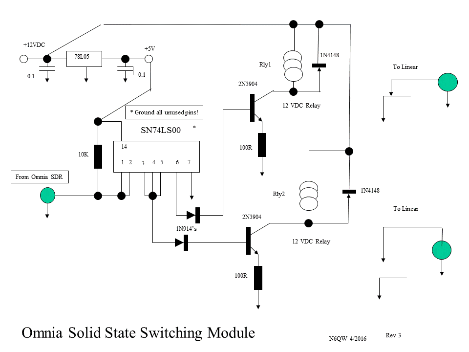
Added schematic for the linear amp switching circuit. 4/24/2016
Added Photo of the Omnia SDR working with the Raspberry Pi2 4/26/2016

In 1959 when I was first licensed, a modest station occupied a large part of the operating desk. Typically a first station might be a Hallicrafter's S-38E receiver (also known as a Widow Maker because it was operated directly off of the power mains). If you got the plug in the socket the wrong way and upon touching the radio you very likely got a hefty dose of 110 VAC. The idea was to be cost effective, thus no power transformer, although the price of that jewel in 1959 is like paying upwards of $400 today.
 
To match that radio were a variety of transmitter kits from companies no longer in business today like Heathkit, WRL, Eico and even Ameco . Of course many rolled their own from plans found in QST or the ARRL handbook when those publications fostered home construction. Sadly today that focused has shifted. Thank God for the GQRP SPRAT and QRP Quarterly where many home construction projects abound. I should mention my first station was a converted ARC-5 receiver and the transmitter was a 6V6 crystal oscillator on a wooden chassis. The really high performance radios were simply out of my league. The Collins equipment was like a whole years salary in 1959. The high end Hallicrafters were in the same ball park. So it was that many an entry level station was by today's standards pretty marginal. In 1959 that rudimentary station operated CW only!
 
But there is a nostalgia side to some of that old gear especially when a rusty old S-38E shows up on our doorstep perhaps with a burnt out front end because of the 110 VAC findings its way into the first mixer tube when the plug was inserted in the wrong direction. Innate in all hams is the thought --"hey I can fix this and get it working again". But once you get it working again --it is still an S-38E. This is akin to putting lipstick on a pig. At closing time, no matter how much alcohol has been consumed, it is still a pig!
 
[For those who are scratching their heads -- many of the cheapo radios did not employ a power transformer but used a two wire system where one side was hot and the other neutral. If you had the hot side to ground then when you added a ground to the hot chassis you would see sparks fly. Many times that ground connection was you! Thus the term widow maker!]
 
Fast forward to 2016 and we now have the very best of all worlds with the mating of computers to our ham gear and the cash outlay in today's dollars is less than the cost of an S-38E. Yes today's radios are "digi", involve black boxes and in the background, computer number crunching; but the final results are amazing.
 
Below is one of the latest offerings from Omnia SDR (click on Omnia SDR )which I believe is the successor to the Peaberry. It is an SDR radio that can optionally be bought as a total part kit rig or one that is mostly factory assembled. For those who hate to wind toroid transformers you can even purchase a fully assembled toroid kit. Note the diminutive size of the Omnia SDR when compared to the mechanical pencil and the 15 inch monitor.


The Omnia SDR comes in various frequency ranges and the one I purchased covers 60, 40, 30 and 20 Meters. Other variants cover above and below those bands. Given my limited time availability, I bought the semi kit and the toroid kit. The total cost was around $180. Assembly beyond the semi-kit involves installing the band specific filters and the final RF amplifier components (BS170's like the SoftRocks).
 
The Omnia SDR has some very nice built in features including the I/Q Signal Processing right on the board and other features  include external linear amplifier switching and controlling an external antenna tuner. The Omnia SDR is supported using HDSDR (a free software program) but can be run using Power SDR or Quisk. My initial setup is with the HDSDR. Beyond the Omnia I have a shack computer running Windows 7, and the internal computer  sound card handles the receiver audio output and the microphone input. I ran a short test with a Symba USB sound dongle in place of the internal sound card and it works as well for these functions. This configuration was tested as I will be migrating the Omnia SDR to a Raspberry Pi3 and will need the Symba for those same functions.
 
To date after about three days of operation all on SSB I have made about a dozen contacts on 40 Meters with half of those running barefoot at one watt. I was even heard in Hawaii on 40 Meters running only one watt. The received audio is simply amazing and having operated an S-38E can only say it is like the difference between the dark ages and today. Below is a close up of the Omnia SDR with the only connection to the computer being the USB cable as seen in the upper right hand side of the board. The hand sketch in the photo is an electronic interface I am designing to control a linear amplifier from the Omnia SDR. I will formally post that schematic and photos of the interface board.
 
 
The Omnia SDR Company has chosen the HDSDR software as the officially supported software so that their product support can be focused around a singular software. The initial setup of the Omnia SDR rig requires the use of this software. That said, once working, the user is free to use any variant of SDR software based on their own preferences. I intend to migrate to Quisk and the Raspberry Pi3. Below is a photo of the HDSDR display.
 
 
I am truly impressed with the Omnia SDR and am looking forward to continued usage of this kit. By the time you add the Raspberry Pi3, a Lapdock Matrix 4G and the Symba USB sound card you will have invested less money than what an S-38E cost in 1959 --and all low voltage operation --no widow makers here.


This schematic includes two modes: one where a normally closed contact is required and the second, more common where a normally open contact is required.
 
Below is a photo of the completed circuit board.


Omnia SDR mated with a Raspberry Pi2


73's
Pete N6QW


Thursday, March 24, 2016

A Motorola Lapdock added to the RPi2 and Softrock V6.3

A new twist to Portable Rigs!


I have just added a Motorola Lapdock tothe Pi2/Softrock SDR Rig. Amazing technology! Portable operation is but a few keystrokes away. Pete N6QW 3/24/2016

Wednesday, March 2, 2016

Raspberry Pi2 and the SoftRock V6.3ng SDR SSB Transceiver

New Direction -- Using the Raspberry Pi2 with a SoftRock V6.3ng  as a SDR SSB Transceiver.

I have lost interest in continuing with the Simpletransmitter. Info has been provided to build the transmitter and I am not pursuing that project any further.

But I have successfully implemented  a Raspberry Pi2 with the V6.3 SoftRock using Quisk as the SDR Software in a 40M SSB Transceiver. See the video below


73's
Pete N6QW

Tuesday, February 9, 2016

Simpletransreceiver ~ Transmitter Stages Part 1

Heating Up the Iron ~ Transmitter Stages #1


After some six weeks of being off the air and tending to a family medical emergency, we are ready to start building the transmitter portion. While I was "noodling" over the transmitter stages I realized that many of the circuits used in the receiver stages are simply "ported over" for use in the transmitter. In the lower level stages the one new circuit board is that of the microphone amplifier. According to the LT Spice once again the "home built" Dual Gate MOSFET works quite nicely in that circuit element. So to be true to our initial design premise -- we will continue to use J310 DGM's in the transmitter blocks.
 
By way of review below is the transmitter block diagram with a special note that the stages with the red asterisk are a direct lift from the Simpleceiver. To that should be added the carrier oscillator. At one time I had thoughts of sharing that with the  in the Simpleceiver. It will now be either a separate oscillator similar to the receiver BFO. [I have already found 4 crystals that are a very close match to the BFO frequency] or it will be CLK2 out of a Si5351


 We'll start first with the microphone stage and once again using our template for the DGM  made from two J310's, is used. Frankly this stage is critical to a high quality sounding station and so we attempted to tailor the audio to the range of about 100 Hz to 4.5 kHz. Your signal should have presence without being "hissy".

Since the rig has been designed for use on 40 Meters the builder will undoubtedly encounter the Spectral Purity Police, many who have never homebrewed a rig, but are running high end SDR boxes with 52 inch LED Displays whose only goal in life seems to be to commenting on how bad your signal sounds. We wouldn't want that.


 We are reposting the schematics for the BFO (we'll now call that the carrier oscillator), the IF amplifier stages and the crystal filter. For the transmitter you must use the 4 Pole Crystal Filter. Please review the earlier post on the building of the crystal filter -- there is some art, science and pure black magic to building a successful filter. Do not believe those who tell you they built one in five minutes --5 hours is more like it.

The low level stages use packaged Double Balanced Mixers, the SBL-1 which are 7 dBm devices, meaning you need 1.414 Volts Peak to Peak to drive these DBM's. Some prefer the ADE1-l (both are from Mini-Circuits labs) which is a 4 dBm device that only needs 1 volt Peak to Peak of RF drive. Caution the ADE1-L is a surface mount device and is small. For the SBL-1 pins 2,5,6 and 7 are grounded. Pins 3&4 are connected together and this is where the audio is injected. Pin 1 is the output pin and Pin 8 is the LO injection Pin. Looking at the top of the SBL-1 package the letter M (as in MCL) is over Pin #2.

There are many purists who believe unless you make EVERYTHING then it is not true homebrew. You can make your own DBM -- I have three videos on youtube that show you how to do it. But you will never achieve the performance of something made under exacting factory conditions. You will also find that a homebrew DBM will need more drive like 2 Volts Peak to Peak. In several of my published articles I have used homebrew DBM's and will sometimes get emails like "Your homebrew DBM design doesn't work!" Well friends it does and often I hear back that the person having difficulty lost track of the windings and it was wired wrong. Save yourself grief and just buy the SBL-1 and get on with it!

The IF amplifier schematic is presented below and much like in the receiver the output has a resistive pad ahead of the crystal filter. Once again we must match the in/out impedances to this this stage. The output of the SBL-1 (pin 1) is at 50 ohms and the input to the DGM is set a 2.2 K thus we have a 1:44 match (2200/50 = 44). Using a FT-37-43 (it must be a ferrite core) a 3 turn primary (50 Ohm side) will match  with a 20 turn secondary to the input --remember turns ratio squared 3^2 = 9 and 20^2 = 400 ---- 400/9 = 44.44444 --so really close! The output side must match 50 Ohms to 150 Ohms which is the input to the crystal filter so we need a 50:150 Ohm match which is 1:3 which is easily done with an 4 to 7 turn match. 4^2 = 16 and 7^2 = 49 --- 49/16 ~ 3. So close enough.

For the second IF amp stage you must match the 150 Ohm out of the crystal filter into the 2200 Ohms input. You can do it with one or two transformers. In the two transformer case it is 150:50 (7 to 4 Turns) and then 50:2200 (3 to 20 Turns). I recommend doing this since you clearly understand the impedance match. Or you could do it with a single transformer where you match 150 to 2200 Ohms which is a 1:14.666 and thus 6 Turns to 23 Turns would get you close 6^2 = 36 and 23^2 =529 ---529/36 = 1:14.7. The resistive pad is not used on the output of the 2nd IF stage.


Following the 2nd IF stage the signal is fed into Pins 3&4 of another SBL-1 which is used as a frequency translator. The LO signal supplied either by an AD9850 or an Si5351 is fed into Pin 8 and the output is taken from Pin 1. The signal out of the frequency translator includes the sum and difference frequencies and so we need to run that through a Band Pass Filter to select the difference frequency ( 12.096 MHz - 5.0 MHz = 7.096 MHz).

Repeated here is the 40 Meter Band Pass Filter that is 50 Ohms in and out. So it simply connects to the output port of the SBL-I which is at 50 Ohms (Pin 1).


Finally is the circuit board layout that can be built with the W1REX MePads. You will note there is space on the board for the SBL-1 Frequency Translator and the 40M Band Pass Filter.


Lot to swallow here but this should keep everyone (so OK probably at this point maybe 3 or 4 of you) busy building the hardware.

Thanks to all who inquired about the XYL -- she is home and returning to her usual old self. The metric here regarding her return is how much she complains that I am a ham radio operator. She has always hated the hobby and now that is going on 49 years!

73's
Pete N6QW

The Risk of Power.

 What happens when the faithful lose faith? We don't know the result but now it is time to pop more popcorn as the interesting part of t...