Yesterday I received an email from Jim up in 7 land inquiring about some Arduino sketches and problems compiling the sketch. I think some of the code was provided by me. I too at times have noted some issues with sketches that previously complied "slick as anything" but then started to hiccup.
Has any one heard about Arduino code that may contain viruses?
Pete N6QW
SS Podcast #210 we talked about the Vintage Sideband Roundtable ~ at any minute smoke and flames can come from an old boat anchor. It is true!
Try this with your uBitx!
Pete N6QW
Just can't leave well enough alone! #4
Search this blog for the Simpleceiver and you can see the painful detail on how to build one. The other day I was thinking about the original Simpleceiver and how that I still had most of the prototype boards still screwed down to a chunk of wood. Frankly I was OK with the 12.096 MHz crystal filter but still felt it has some short comings. So then I thought about popping in a 9 MHz GQRP Club Filter in the IF stage and that caused me to revisit the IF amp design and what it takes to move it down to 9 MHz which is the filter Cf. A bit of digression as it was on this very prototype board that I came up with the single pass relay switched amplifier approach. Essentially the signal passes in a single direction through the IF Amp Block and on receive the signals coming from the Mixer Stage (SBL-1) are passed through the IF amp Block on to an ADE-1 which is now the Product Detector. With two relays and a bit of coax on transmit the ADE-1 is now the Balanced Modulator and its output is relay switched to the input side of the IF Block Amplifier stage and the Output Side which is now SSB is relay switched to the SBL-1 which is now the transmit mixer stage. There is no switching of the LO and BFO --just relay steering of the signals through the IF Amp Block Stage to always pass in a single direction. The 12.096 MHz IF Amp block had just a few changes to resonate the tank circuit to 9 MHz. The 5.13 uHy inductor is made with a T-68-2 (Red Core) and has 30 turns of #24 enamel wire. The 400 pF is a 180 and 220 caps in parallel. Following the 2dB pad is a 6T to 19T matching transformer on a FT-37-43 Core (#26 enamel) as this matches 50 Ohms to 500 Ohms which is the Filter Zin. On the output of the filter is a 9T to 19T matching transformer to match the Z out (500 Ohms) to the input which is 2.2K [9^2 = 81 and 19^2 = 361. 361 / 81 = 4.45. 2.2K/500 = 4.4. Close enough for government work. ] I needed a bidirectional amp stage ahead of the Band Pass Filter with one half being the receive RF amp and the other half the Transmit Pre-Driver. I had a board I made that was designed for the AG30386G MMIC amp and so I used that approach. Just as easily I could have used another J310 stage with relays to do the same job but opted for the MMIC stage since I had the board and the devices. The transmit driver is the standard 2N3904/2N3866 from EMRFD and the final is the IRF510. The Mic amp and Audio Amp were already on the prototype board (2N3904 for the Mic Amp and the Audio Amp is the NE5534 and LM380). I have now switched over to a newer (and better) mic amp design which now gives a flat response from 250 Hertz to over 10 kHz. The console to the left is to be replaced as it was just pressed into service to get the project "hot on the air". The replacement is shown in the third photo.
-
Yes a real kluge --but works --several QSO's so far including one running 600 watts! You have to love those GQRP Filters. 73's Pete N6QW
So OK I have a lot of transceivers that I have collected with most being acquired on the cheap. So while there may be many, the invested dollars are relatively low. Periodically I will drag one out of the storage bin and try to fix the unit. This is done more so as a technical challenge; but often I drive myself nuts in the process.
Here is a recent example. Several years ago I bought a Ten Tec Triton IV Model 544 which is the digital version of the Model 540. Several years ago I actually converted a 540 to a 544 and you can see that on my QRZ page. It was also a subject of an article that appeared in QRP Quarterly. Thus I have a bit of background with this very FB Ten Tec rig.
The Model 544 I have supposedly was hit by lightning and was inoperative. Well that was true; but not a total disaster. (That is why I got it so cheap.) Replacing two back to back diodes that were shorted ahead of the reed relay that disconnects the receiver during transmit cured one of the problems and a new set of finals cured the other major problem. The rig is now operational.
BUT and the Big BUT the display does not stay fixed on frequency. You get that annoying drift of a few hundred cycles and the ever flickering last digit over time. Guys it is still an Analog PTO with a digital readout. That had to get fixed.
Most if not all Ten Tec rigs have an accessory socket where you can add an external VFO and the Model 544 has that functionality. This is where you laugh a bit … on the back panel is an octal tube socket fitted with a jumper plug. [Octal tube sockets and solid state rigs -LOL]
The stock configuration brings the LO signal to Pin 8 where it is physically connected to pins 6 and 7. The theory is that with these three pins connected, the transmitter and receiver are on the same frequency. With an external VFO connected to pins 6, 7 and 8, then a switching arrangement in the remote VFO enables:
Transceiver operation on the remote VFO
Transceiver operation on the Model 544
Receive on the Model 544 and transmit on the remote VFO
Transmit on the Model 544 and receive on the remote VFO
Thus my plan was to essentially uncouple the internal LO which has various ranges depending on the band. The basic PTO operates in the range of 5 to 5.5 MHz and that is used directly on 20 Meters. For the other bands the PTO is mixed with various crystal frequencies to produce LO signals in various ranges from 5 to 19 MHz for injection into receiver and transmitter mixer stages.
I have a band switched Arduino/Si5351 that I simply programmed to match the ranges of the LO for each band. You can even do this with an AD9850 as you only need the LO as you retain the BFO built into the Model 544.
Now you don't even need a display on the Arduino/Si5351. By injecting the proper LO frequency and having the band switch on the Model 544 set to the right band, the internal Model 544 displays the frequencies just like when the PTO was in the loop.
I was joyous as the only modification to the Model 544 was to unsolder the Jumper wire connected to Pin 8 on the external plug. There is no messing with the radio innards.
In fact if you can locate a non-functional 8 pin tube just remove the tube itself and use the base as a new plug. If you go this route then you can do some amazing things like separate the receive and transmit frequencies. My LO sketch includes two VFO's so now you have even greater capabilities.
I made all of the connections (one) and my plan worked. I could tune all of the bands and better yet Ten Tec had an auxiliary band switch to cover the four ranges on 10 Meters. I can do it with just one 10 meter range.
You do the tuning on the remote VFO but the Model 544 does all of the displaying. What is also nice is that I can manually change the step tuning rate which is nice when you want to QSY across the whole band. The one thing I have not resolved is the offset tuning --not a major issue just something not done as yet.
So I am listening on the various bands and I do happen to have a display on my remote VFO assembly. The Arduino/Color TFT is reading 16200800 and the Model 544 is reading 7.200.8 (with the 8 being a Green LED). Then it happened the last LED on the Model 544 starts to 'flicker up/down" but my Arduino/Color TFT which has a greater resolution is rock solid.
So what conclusions can you draw from this?
Something else aside from the PTO and the Crystal mixing circuit for the various bands is at work.
There is a crystal clock in the internal Model 544 LED display board. It may have some issues and therefore is causing a shift in the time base.
The BFO frequency is summed with the LO in the display circuitry so that the BFO is added or subtracted from the LO depending on the band. The IF is at 9 MHz and thus the LO runs in the 12.5 to 13.0 MHz range for 80 meters. (Subtraction LO-IF.) Whereas the LO runs in the 12.0 to 12.5 MHz Range for 15 Meters (LO + IF). Possibly there are some issues with the circuit that mixes the LO and BFO for the display.
In an earlier Model 544 that I owned there was a problem with the ua723 voltage regulator that had to be replaced and that cured a frequency jumping problem. I did initially replace the 723 regulator as it did have a frequency jumping problem; but that did not resolve the flicker.
So the concept of a remote VFO is doable with a minimum (and reversible) modification to the Model 544 and this should work for other rigs like the Drake TR-4 or Yaesu FT101 both of which can have remote VFO's. I did something similar to this with an Atlas 210X --so lots of possibilities for updating the older boat anchors.
If you want the code send me an email to n6qwham@gmail.com.
If you have any ideas about the flickering send me an email to the above address.
Calling all Junk Boxes, N6QW is looking for a part!
Recently I bought an SBE-33 SSB Transceiver for $52.30 and have been doing some major restorations, which principally involved a great deal of capacitor replacements. I did have to replace the speaker which was blown; but had an exact replacement taken from a Junker unit.
I have had the rig on the air and so far I am impressed at the 1963 technology --even with an analog VFO. Yesterday running my SB-200 I worked Croatia, 9A5W, Nikola on 40 Meters. That is a big first for me and I got a notable report of how good it sounded.
A short story --- the dial markings are at every 5 kHz and a ham running a FLEX5000 contacted me to tell me I sounded bad and was not on frequency (7.208 MHz). I asked that he give me some chatter wherein I zero beat him. Then when I transmitted back at him inquired about the signal. He said I don't know what you did but you fixed it. You are now on frequency and the audio is clear. Wow --he has been a ham for 5 years and well I will stop there.
The Junker SBE-33 has provided many mechanical parts that were missing (the speaker of course and mostly shields although I did have to fabricate one of the shields). Should mention all the transistors are original save for one and I think I have that one too. Look up the specs on a Philco 2N1727 just for fun. It is now mostly stock and I am down to one item -- The Panel Meter.
It is blown and I attempted to repair it but can't get it loose from the case. Thus the only option is to find a replacement meter. Not any meter but one that came from an SBE-33. I guess blowing the meter was a problem, as the Junker is minus the meter too.
So if you have an SBE-33 sitting gathering dust in your garage, here is your chance to move it elsewhere. I need just the meter but will take a whole rig. Please advise price and shipping to 91320. I can be reached at n6qwham@gmail.com.
73's
Pete N6QW
3/11/2019
Arduino: How to add the CW capability!
It is always best to turn off the soldering iron first (and to also know which is the "hot" end) and go through a bit of a noodling process to actually think about what you want to do.
Firstly we need to take a look at the Pin Count. If you are using one of the really neat Color TFT displays as I have in many of my rigs you have taken up quite a few of the Arduino Pins. At this point you might want to start looking at an Arduino Mega 2560. Having 54 digital pins will not constrain you on inputs/outputs and the 16 Analog Pins is also a bonus. If you will be using say a 20X4 LCD then the use of the I2C buss frees up a lot of digital pins and opens up the possibilities for using a Pro-mini or a Nano. Overall size of your rig may force a smaller physical size microcontroller. Depending on how much you want to display you might even get by with an 8X2 LCD. When I documented my Bitx40 build which was fabricated just before the Raduino was added, I used an 8X2. You can see that on my website at www.n6qw.com.
So from a Pin Count and for the normal SSB operation we have the encoder and step select ( 4 pins including ground). The I2C Buss (4 pins, but two are 5 VDC and Gnd). USB/LSB Select (one pin), VFO A/B Select ( one pin) and TUNE (one pin). True not all are digital pins, as five of those use Analog Pins 1 through 5. So we still have lots of Digital Pins to work with using the Uno, Nano or Pro-Mini.
Functions we are looking to add to the Arduino: the very first is to have a switch ( 1 pin) that says check if this pin is active and if so go to the CW routine. The very 1st item on the list is to shift the BFO to USB for CW Receive.
Because we are using the Arduino we can accurately generate audio tones and thus we have the option as described earlier of using the tones to do CW. In one of my transceivers when I engage the TUNE function at the end of the pulsed tone I sent my call sign at 988 Hz. It sounded pretty decent. BUT we will have to do a lot of RC filtering as the TONE output is a Square Wave it would be nice to pump a sine wave down the throat of the Balanced Modulator. We will need to designate one pin as the TONE output that we later smooth up.
For our CW application there are tones closer to 700 Hz and I will find the appropriate one for the code. By using two pins on the Arduino we can accurately generate timed dits and dahs. By using one of the analog pins (we have three spare ones A0, A6, A7) we could include a speed control so that even though you physically send slower the output can be at a blistering 100 WPM. That will show those SSB only guys!
In the code for turning on the Si5351 LO we may need to include a constant, call it c, in addition to the standard generated frequency and for SSB the constant "c" = 0. But for CW the constant is the amount of the offset. This may not be required but is put on the list so it can be added or not included depending on further noodling.
A timed output pin, (only active on CW) would key the PTT and hold the transmitter on for some time period. This output responds to when either the dit or dah key is engaged. Another pin could actually signal different delays --or two pins four delays.
This is just some initial noodling on my part. But mind you a real Arduino programmer would have all of this as menus where you could select timing levels output speed and delays. But I do think this is a way of adding the capability albeit a bit klunky.
I will have to dust off the QRP Quarterly articles that AI6YR and I wrote to evaluate adding keyboard sending to the mix as that would change some of the functionality I described.
Now the thought occurred to me (and assuming unattended operation is OK for this application) --using canned code and reading the CW, in the morning turn on your rig and all day long the rig is having QSO's while you are at work. How cool is that?
73's
Pete N6QW
The Answer is Not a Flippant: Carefully!
[Author's note: A friend in VK4 land made an inquiry about CW operation. I find that 99.99% of my operating time is SSB. But others spend a greater time on the air using CW so why not share some info and data that I have stashed on my computer where a SSB rig can be made to work CW. This also open the possibility of filter switching for a more narrow pass band. With Arduino anything may be possible.]
My shack is full of homebrew SSB transceivers but only two have CW as an option as well as the normal SSB functions. A design of having both modes must be done with great care and forethought. The rig which does have the best CW functionality is my KWM-4 which hit the airwaves in 2013.
I spent a great deal of time looking at CW schemes and it became obvious that many commercial rigs included CW as an after thought to aid in the marketing and did not really address the desires and wants of the ardent CW operator.
Here are some of the results of my research.
One method was to simply unbalance the carrier balance control, turn off the mic circuit, crank back the power and flip a switch often called MOX (manually operated transmit). Thus change over always involved the MOX so no break-in. You essentially keyed the PTT. The offset was poor and involved a lot of leap frogging to copy you. Often there was no side tone oscillator.
Another method involved shifting one of the BFO frequencies straight down the throat of the Filter Center Frequency (Cf) and then key a buffer stage somewhere in the loop. This method was OK; but often limited you to sending CW on one side band and receiving on the other. I think the convention now is to receive on USB. Some later commercial rigs let you pick CWL or CWU.
Some rigs used a clever approach that employed a tone being generated on "key down" that did three things: 1) the first is you now had a side tone; 2) you now were able to use that tone to key the VOX so you had break-in operation and the third the tone was sent to the microphone input circuit. I think this is covered under Part 97 as tone modulated CW. I think this was the system employed in the Collins KWM-2.
For the most part the "value engineering equation" included only one filter often (in early rigs) 2.7 kHz wide. For a CW signal 500 Hz wide that is a lot of signals snaking through the filter pass band.
But one homebrew rig in particular from the Dec89/Jan90 QST article authored by the Wizard himself Wes, W7ZOI used a separate crystal oscillator and keyed buffer to generate CW. (The rig was a 20M QRP SSB/CW transceiver.) But even this design had shortcomings in that to do CW you had to hold down the PTT switch. I fixed that problem when I built my version of this rig. This the 2nd rig I have with SSB and CW and predates the KWM-4.
Thus when I built the KWM-4, I looked to address those issues and decided on the W7ZOI approach; but having some refinements.
I would use a separate oscillator to generate CW. Somewhere in my travels I found a 455 kHz crystal and this is what I used.
My 455 kHz oscillator was turned on for short periods of time but not keyed. A downstream buffer stage was keyed. This is an old-timers technique as this method reduced chirp and key click as you would have in directly keying an oscillator. The short time I spoke of could be accurately set using a timing capacitor. I like a long time between letter so the code sounded distinct. Many CW operators are plain and simple crappy senders using a straight key.
Next the keyed buffer stage was fitted to the circuit so that the CW signal was injected into a bilateral stage ahead of the crystal filter. This was done for two reasons: the first being I could tweak the 455 kHz signal so its offset was more in line with 700 Hz and secondly I did not have to worry about any effects of the filter and downstream circuitry. A small board mounted relay engaged only in CW on transmit disconnected the Mechanical Filter and the preceding bilateral stage fed the 455kHz RF.
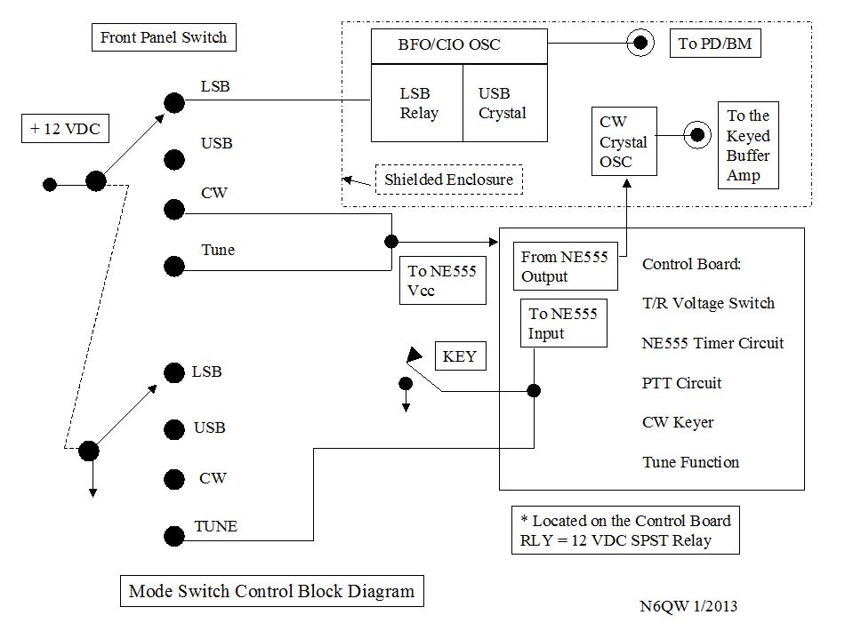
I then developed a control circuit that did several tasks. One task was to provide break-in operation with a second to have functionality for both tuning the rig with output that required no "key down" or regular CW operation. As a bonus this circuit also providing the switching of voltages to go from Receive to Transmit and even included the usual outboard linear amplifier control. From a block diagram standpoint this is what it looked like.
This is a schematic of how it was done.
I spoke of the relay bypass on the IF Mechanical Filter
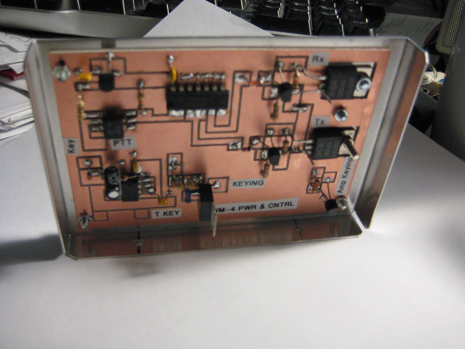
Some Snaps of the Control Board
Yes Virginia, all of the boards were made on my CNC machine. I think it turned out pretty cool. But then again I tend to think all that I do borders on genius.
Now with the advent of the Arduino and the Si5351 a lot of what I did six years ago will be just a few pieces of hardware aside from the Arduino. To wit the 1N914's coming off a the 7400 IC could now connected to pins on the Arduino. The timed voltage off of the NE555 is just a Pin Output to a DC switch that is in an "OFF" state until keyed.
The 4.7 UF was a timing cap. But suppose we use one more pin with a switch that would give you a default time value and engaging the switch selects a different value. Two switches could give you four time values.
I would consider the use of the third clock on the Si5351 that would provide the CW oscillator frequency that would operate in the same way the standalone did in the KWM-4 and that would feed a keyed buffer.
All of my sketches include a TUNE function that generates a pulsed 988 Hz tone that is fed into the Balanced Modulator. That same code can be modified to provide the timed voltage to the buffer as well as the side tone and show on the display you are in the CW mode.
I just may have to build what I suggested and then this could be used with other homebrew SSB transceivers. At this stage it is always best to noddle a bit more but I think I have sketched out a possible roadmap to add the Arduino to the mix. If you used a Mega 2560 (more pins) then it would be possible to add my CW sender software so you could add a keyboard for sending CW --and even call up canned messages. With the Arduino anything maybe possible! (For those still subscribing to QRP Quarterly several years ago, Ben, AI6YR and myself did a series of articles on a CW Sender using the keyboard.)
The Building of a SSB Transceiver ~ You can do it!
2/22/2019
At Christmas my 3rd son gave me a transducer speaker that mounts to a piece of foam board and I sit here amazed at the sound reproduction. The amp driving the speaker is the 2N3904 and LM386. So it will provide more than just headphone volume (with a 100 Ohm resistor installed). I received a comment about the 100 Ohm resistor and just for fun substituted a 10 Ohm in the LT Spice simulation and saw no difference in the output curves. The short video tells much.
Pete, N6QW
2/21/2019 ~ Go Daddy Now Fixed! The audio Amp Schematic is on the website.
2/20/2019 ~ Problems with Go Daddy!!
For over 24 hours I have been trying to upload updated schematics and information to my n6qw website. It seems like Go Daddy who hosts my website has some sort of issue with a windows server. One solution that offered was for me to spend more money and move over to a Linux server OR just wait until they get around to fixing the problem. Not only is it a cost issue but also I would have to start from scratch and rebuild all five of my websites. This makes about as much sense as declaring an emergency so the emperor can have his wall.
My alternative is to wait a bit longer to see if they can resolve the problem or just post the info here. Here is one of the updated schematics. Perhaps if any of you have a Go Daddy account you may have the same problem.
Pete N6QW
2/18/2019 ~ Toroids are not self shielding!
I noted that after installing the shield on the left hand side there appeared to be a detuning of the band pass filter. Despite what many have said toroids are not necessarily self shielding.
When I installed the side piece, I thought there was a sufficient space gap between the steel based side panel and the T-68-2 cores. There was not and so the BPF was being detuned. There just was no way with the side panel in place to re-peak the BPF to the proper value unless I followed the practice espoused by Ian Roussel (Full Custom Garage on the Motor Trend Channel) which is make a hole.. The "A" change was to cut about a 1 and 1/8 inch round hole in the side panel stiffener right over the BPF. This accomplished two things. Firstly it reduced the effects of the steel on the BPF and secondly to provide access to the trimmer caps so that the BPF can be tuned with the steel side piece in place. Worked perfectly -- the hole does not affect the stiff properties of the side bracket. We are good to go. The 2nd photo below shows the side piece without the access hole. You have got to love when a plan comes together!
Pete N6QW
2/17/2019 ~ Be sure to visit www.n6qw.com where the project is documented and new schematics have been added over the past two days. Learning to Hem ~ No we are not sewing!!!
In keeping with trying to use stuff I already have knocking about the shack we now address a common problem with homebrew construction: making or buying a case enclosure. The problem is compounded by the fact the front panel is from the former 30M CW transceiver project that was a QRP Quarterly article. But the back panel came from a transceiver that was rebuilt at least three times.
Now for the disconnect. The front panel is 4 inches high and the back panel a mere two inches. Standing alone the front panel flexes as you spin the encoder --not a good plan. Thus to stiffen things we need to connect the front panel to the back panel to add rigidity. We essentially have a trapezoid and how to fabricate those two pieces, one for each side, and not spend a fortune on material.
One of my currently favorite TV shows is the Velocity Channel (now Motor Trend) and my new hero is Ian Roussel of Full Custom Garage. This guy uses what is at hand and often comes up with very creative solutions. In one episode he needed a round metal structure to house the odometer that was being affixed to a new dashboard. He spotted his dog's water bowl which it turned out was stainless steel and just the right size. The poor dog now drinks out of a plastic dish. But it is that sort of thinking we need to employ when we fabricate our homebrew rigs.
A trip to Home Depot yielded a piece of galvanized metal flashing that was about 8 X 11 inches. The price was $1.14 and was enough material to make two sides. But wait you are thinking that stuff is awful flimsy. True; but if you bend it over along one of the seams --it becomes rigid. A pair of Tin Snips, a metal straight edge with scribe and a bench vise is all that is needed to make these very durable side braces. The galvanized metal can be soldered as well as painted. Thus the bending over and doubling is known in the fabrication world as "hemming".
The first item on the list should be a manila folder that will serve as a pattern to overlay on the sheet metal and provides a template to scribe the outline. Keep in mind you have right and left hand pieces and thus you must flip the pattern over to draw the scribe lines for the different sides. The 1st photo below shows the template of the sides and you can see the bend line for the hemming. On either end add 1/2 inch of material that is bent over and will provide the anchor points to the front and back panel.
You might have to "play a bit" with the metal bending so get two sheets of the material. The finished rig is a far cry from the boards screwed down to work bench as it was initially built. Nice looking Rig, Pete!
Ian Roussel would be proud.
Pete N6QW
2/15/2019
2/13/2019
[2/11/2019 I have started publishing schematics for the Simple SSB on my website at www.n6qw.com. Although it is doubtful that many (if any) would take up the fabricating of this rig, there just may be one or two who have an interest.]
Just the other day I was having a very nice QSO with Gene W6QFU and we exchanged our station line up. W6QFU is lucky in that he just recently acquired a very nice ICOM 7300 and has joined the ranks of perhaps over 100,000 other hams world wide who now have that rig sitting at the operating position. Some would suggest it is an appliance rig; but at the same time it is a great sounding rig that undoubtedly is very popular and the current price point puts it in reach of many hams. Guess there is a link to price point and the numbers in shacks around the world.
On my end --yes, yet another new rig just finished and W6QFU was the third contact on that rig. So I was anxious to see how it held up. Well I might add... ARRL as previously reported will start a new podcast one month from now called "So What Now?" A possible answer to that question (or perhaps it is a challenge) is to suggest you build your own SSB transceiver. Trust me what I am suggesting you build is not in the ICOM 7300 class; BUT it puts out a respectable signal with a rock solid frequency stability and it is something you built and can be built for about $100. [YMMV depending on how much junk you have in the junk box.]
But let us go back in time to review SSB transceivers starting in the late 1950's and early 1960's. BOOM there was an explosion of technology in that time frame starting with the Collins KWM-1 and KWM-2 (the cost --read a years salary for most middle class working folk) to more modest rigs that were less costly. Heathkit did much for the hobby in offering single band transceivers that could be had for about $100. I remember being on Midway island (actually two island Sand and Eastern Island) in 1963 where a fellow Navy ham on Eastern ran one of those rigs into a 13 dB gain Rhombic antenna pointed at the US. Everyone wanted to talk to him--firstly he was DX and secondly that gain antenna took that 100 watts and made it look like more than a KW (like 2KW and you can check the math [10*log(2000/100) = 13dB]) But even the simple Heathkit rigs involved some pretty complex circuitry to receive and transmit a signal using common circuit elements.
There were many complicating factors in building a homebrew SSB rig in the 1950's and 1960's
Socketry --yes you had to do all of that metal bashing and mechanical engineering to layout all of the tubes and components that had to be affixed to a large aluminum chassis
Power Supplies. You often required Filament, Bias, LV, HV and control power to operate the rig. We are indeed fortunate --12 VDC and we are there today
Front panel controls abound as does a space reservation for the Analog Dial Readout
So there was much involved aside from just a few schematics. In todays rigs none of those issues exist as many circuit elements simply solder to a few pads. Socketry is minimized so you can feel secure in selling your set of Greenlee Chassis Punches at the next block yard sale. You won't need them. A 12 VDC well regulated supply or even batteries can run your rig. You only need to cut out a rectangular hole in the front panel for your favorite display (LCD or Color TFT). If it is a touch screen then that will reduce further the number of controls needed
Fast forward to today some 60 years later and building a transceiver is much easier and uses far less components thanks to IC's, PLL's and inexpensive commercial crystal filters. Let me take a moment to discourage the use of homebrew crystal filters especially if you have not previously built one, and two if you lack some pretty decent test gear. Sure you can purchase crystals inexpensively but that is only 5% of the task. So reject all of those claims that you only have to buy 5 crystals at 40 cents a piece and you are there --you aren't! INRAD sells a nice 4 pole 9 MHz experimenter's filter for about $30 and you can also buy 9 MHz filters from the GQRP club for about the same shipped to you. Yes I do have several rigs with homebrew crystal filters so I do speak with experience. But it is a simple decision if you do not have that experience --buy the filter! So lets talk a minute about the SSB transceiver architecture. and we'll proceed first to the block diagram.
Many rigs today are bilateral or as some prefer bi-directional in that a) signals can be routed in two directions through the circuit element and b) because of (a) you can use that circuit element in both transmit and receive. Here is an example of one circuit element that I frequently use... a bidirectional IF Amplifier Module as shown above. This module has four transistors, a bunch of caps and resistors, two matching broadband transformers, a crystal filter and a relay to bias parts of the circuit to change the signal direction. The common 2N3904 and 2N3906 make up one amplifier stage and following the crystal is a second identical stage. The amplifier circuit was invented by Plessy and appears in EMRFD (just so it has street creds). Here is what is happening .. with one bias condition the two 2N3904's take on the amplifier role. With the alternate bias condition the 2N3906's are doing the heavy lifting. This circuit is good up to about the 6 Meter band and a single amp pair is good for 15 to 17 dB of gain. Here are some notable items. This is a broad band circuit --there are no IF transformers and there is nothing to peak or tweak. The resistor compliment for a single amp stage is 22 Ohms, 2 X 100 Ohms,. 2X 680 and a 1K. For caps -- six each 100 Nano Farad. The power source is actually 6 VDC but I run mine on 8 VDC through a three terminal regulator. Add in two FT-37-43 matching transformers [19 Turns solenoid wound tapped a 6 turns. The 19 turns squared is 361 and the 6 turns squared is 36 --thus 361/36 = 10. So this transformer matches the 50 Ohms of the Plessy to the 500 ohms on the GQRP filter.] Including the Linear Amp control ( another 2N3904) there are eleven transistors and FET's along with two packaged ADE-1 Double Balanced Mixer's an Arduino Uno R3 (because it was in the junk box) a 16X4 Seasick Green LCD (also a junk box refugee). BTW I was looking at some 16x4 Blue White LCD's --$8 shipped from the USA. Lest I forget the GQRP 9 MHz crystal filter. If you use the INRAD it is a 4:1 match as the INRAD's are 200 Ohms. This may be a good place to stop for now… but to whet your whistle:
Interesting note this front panel was cut out of the front panel that was used for the 30 Meter CW transceiver that originally was a QRP Quarterly article. I should tell you that I was encouraged by QRP Quarterly to design and build this CW rig so it would appeal to those QRPer's who dominate CW. I did as was suggested and did make one contact to prove it works . The rig then went into the never to use again and possible use in other projects bin. There it has sat for five years. Now is the time to use it! The panel was reversed as it was double sided PCB. The Key is now the Mic jack and where the analog dial was --it was cut out for the LCD. The audio amp stage was cut out of the original main board. There are three empty holes in the new panel. Above the red knob the audio gain control will be installed and the hole in the lower right hand corner will house the audio output jack. and the small hole next to the mic jack will be filled with a bolt and nut. The original panel was 8 inches long and with a bit of juggling and cutting material off of each end the size is now 6 inches wide. Thank you Velocity Channel for giving me some really great ideas! Yes Virginia having a CNC sure makes life a lot easier when you are fabricating radios. The part that was cut off included the former part containing the volume control and headphone jack. The two bolt holes nearest those were enlarged to house one of the toggle switches and the new headphone jack. New panel controls include MOX and TUNE button (red button), Volume control, Main Tuning, USB / LSB Select and VFOA / VFOB Select, Microphone Jack and Headphone Jack. Lest I forget the 16X4 LCD.
Below is the rig screwed down to the top of the work bench. In the very bottom is the IF module, Audio amp and Microphone amp. To the left of the IF module is the BPF and above the IF the bidirectional J310 amp and the single 2N2219 feeding the IRF510. To the right of the IRF510 and the microphone amp is the LPF. The junk in the center is my power buss and some relays used for TR. The RCA plug/cord above the J310's is the linear amp control. The "T" line feeds a 1K resistor into the Base of a 2N3904 with the Emitter grounded at the collector goes to the control line in the follow on linear amp. Take a good look --aside from looking like crap --there are not many parts. I did use it on WSPR and FT8 as well as a few SSB contacts. the future work will involve some packaging to sanitize the look. !
It is a shame that many hams think building a rig is too difficult. Drop me a comment if you would like to see more detail on this project. Oh should mention portions of the design are LT Spice simulations so there is solid science behind the modules. These include the BPF, LPF, the J310 Bi-Directional amp, the 2N2219 driver stage and the microphone amp circuit. Oh --the mic amp design is now the same design used in the audio pre-amp stage. The circuits not simulated are the Plessy amps (from EMRFD) and audio final stage LM386 and the IRF510. I was asked a question about how the Simple Transceiver compared to the Sudden Transceiver Project. There are two areas of comparison the first of which is performance and the second the circuit elements themselves. Performance is equal and thus I am pleased; but the circuit elements do differ and the following explains the differences.
There is some circuits which are alike and some not so. Physically the Sudden is a
smaller footprint. Some circuit differences include:
The IF Module uses the
Plessy amps and external DBM’s. The Sudden using the NE602 provides the mixer
stage and the balanced modulator on the input side and the mixer and product
detector on the output side. The LO & BFO are switched whereas in the Simple SSB rig they feed the same DBM regardless of T or R. The Sudden is a
single pass whereas the Simple is bidirectional.
The simple SSB takes the
pre-driver used in the Sudden and makes it bi-directional so it is the Rx
RF Amp on receive and Tx pre-driver on transmit. The Sudden has a separate Rx RF Amplifier stage
Only one BPF versus two in the Sudden
The Driver and Linear
Amp are the same
The Mic Amp is the same
but the Audio Amp different
The Sudden uses a Color
TFT and Nano and the Simple the Uno R3 and the 16X4 LCD
The LPF’s are the same.
Bottom line ~ not a lot of parts! For those who wonder this is not a Bitx40 repackaged. The Dual J310bi-directional stage configured as a Dual Gate MOSFET has some interesting possibilities. The stage has a manual gain control pot built into the circuit board so that stage gain can be adjusted. This opens up some potential for adding AGC and ALC to this stage so now we can add more additional refinements. One comment I made arising from the Sudden Transceiver fabrication was the opportunity for experimentation. With a change in the BPF and LPF the Simple SSB Transceiver can traverse to other bands. A simple DPDT toggle switch on the front panel could with 1/2 the switch controlling the VFO range and the second half controlling 4 SPDT relays would switch in the proper BPF's and LPF's for each band. One switch, four relays and a few more toroids and caps and you are on two bands.