Thursday, April 4, 2024

April 4, 2024. Converting the IMP TR to a Transceiver.

Converting the W4IMP Transmitter into a Transceiver configuration. Well indeed, who am I to go messing with the superb work done by W4IMP? Bottom line, it is just a terrible affliction of looking at a circuit and seeing possibilities.

W4IMP is specific in his article that this 15M rig is just a steppingstone to an all-band rig he has in the works. So, he too has the affliction.

In 1961 I was halfway through a BSEE, and I doubt I could have designed his original work. But having built so many SSB rigs some 60 years later you get a feel of topologies and what can be done with many years of data stashed on the Internet.

A word here about my rig fabrication process that involves upfront noodling and simulation. My soldering iron is off and will be off until I have looked at a literature search. 


This is not the complete block diagram but shows how to diode steer the Audio Amp/Mic Amps, the New Crystal Filter and the two RF amplifiers such that one is the Receiver RF Amp, and another is the Transmitter Pre-Driver. 

A good stop and smell the roses point is the 50 Ohm input output impedance matching. Consider that the HB Filter likely has a Z in/out in the 200 Ohm range so you will need some 4:1 matching.

The LT Spice simulation below show the RF amp circuits.  About 10dB gain at 21 MHz with 500 mv of input which certainly would be the case for the transmit side. Yesterday's post had the Audio Pre-amp and Mic Amp circuits.

Essentially, you build two Diode Ring Mixers, a Crystal Filter, and 4 amplifier blocks -- two at audio and two at RF. The Driver Stage could be a 2N2905 and the Final Amp a 2SC1969. [The 2N2905 is the PNP equivalent of my go to 2N2219A.]


RF Amp Simulation


The Audio Amp/Mic Amp Simulation


The Key take away is that with some simple circuitry you have the beginnings of an SSB Transceiver.

Lest I forget -- the two HB Double Balanced Mixers circuits.


Start scouring the junk box and just think an unconventional use of PNP transistors.

If you use a 9 MHz IF, then a simple 5 MHz Analog VFO would get you on 20 Meters. That VFO frequency would be a lot more stable than an LC 13MHz VFO. I only mention the analog VFO for those averse to Arduino's and Si5351's. We have a big tent.

Keep noodling.

73's 
Pete N6QW

Wednesday, April 3, 2024

April 3, 2024. Solid State SSB Transmitters from 1961

In the Soldersmoke Podcast #250, I mentioned the W3TLN 20M QRP SSB Transceiver that appeared in an issue of the ARRL Sideband Handbook. It was then I realized I only had one volume of that publication. A tour through eBay found me a different volume in quite good condition for $8. Buy it Now and Done! 

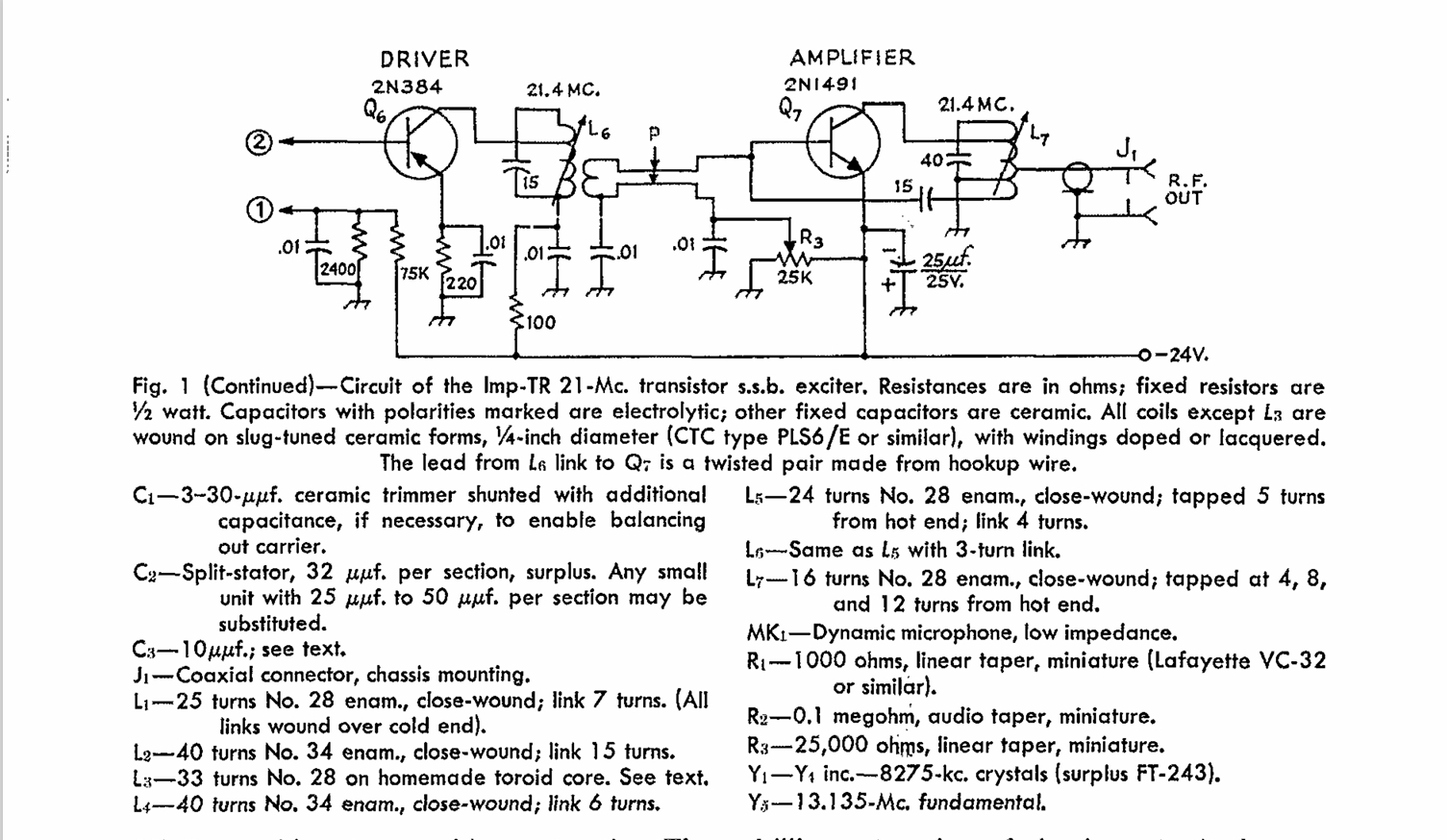
Many of the projects are the same in this version just purchased as the version I have but a new one for me was the "IMP TR" shown below. W4IMP in 1960 created a SSB transmitter using only 3 tubes and was dubbed the IMP. A solid-state version of the tube IMP appeared in the December 1961 QST and thence the 1965 version of the Sideband Handbook. 


The "IMP TR" from December 1961 QST


This would be a cool project to easily replicate today some 60 years later. Well maybe just a little difficult to do. His filter was made from FT-243 surplus crystals where he opened up the cases and shifted the frequency of several so that they would provide the necessary band width. 

This old technique called "rubbering" involved using an HB Lead pencil to mark the crystal wafer so it would oscillate at a lower frequency. Or to pull out the crystal wafer and using a piece of glass with wet Comet Cleanser to grind down the wafer thus raising its frequency. A shot in the dark at best! This is like using a Nano VNA uncalibrated and never having read the instructions for its use.

To make this easier to build, the circuit should be modified to take a 4-pole ladder type filter where you have a chance of building something with today's components and use readily available filter software.

But while you are at it, I also see the possibility of making some modifications so that it could be used as a Receiver and transforming the IMP TR into a SSB Transceiver. The Magic comes from Diode Steering where you can add the new filter AND give rise to a transceiver.


A Receive mixer would inject a signal into L4 back feeding the 4-pole filter and the two diodes in the Balanced Modulator would act like a Product Detector to an audio amp stage. It would be a little more complex than that, but this is a notional starting place. This is not unlike was done in the SBE-33 transceiver.
 

Above is a new PNP Microphone Amp circuit that would feed the winding on L2 on transmit. Using diode steering would only supply a microphone signal to C3 on Transmit. On Receive more diode steering would connect to an identical circuit but at C1 where the circuit is an audio pre-amp stage. Again, just a 1st paper noodling of possibilities.
 
The Supply voltage would have to be changed so that power is normally supplied to the Receive circuits but on TR it would switch to those circuits only used for Transmit. R7 could be a pot to adjust the Mic Gain off of the wiper.

Look at the 2N1491 which was the "hot" RF Device in 1961 -- maybe a watt or two out at 14MHz. The price was like maybe $30. Also note the hybrid nature of combining PNP and NPN devices. It seems strange to be putting -24VDC on an Emitter and to Ground the Collector.

The bottom line is that some of these older projects have possibilities for a current update. Some concerns I would have been if the filter alone would provide enough gain to make this work without some amplification in the filter module. I also see the possibility of replacing the 2N384 with a homebrew Double Balanced Mixer stage at the L4 juncture as this would provide both the receive and transmit mixing.

This is like the TV Show "Extreme Makeovers" where all you have left before you start the rebuild is a bare piece of ground. 

Hats off to W4IMP whose day job I believe was dentistry. Indeed, he left a huge watermark on homebrewing in the early 1960's.

73's
Pete N6QW


Tuesday, April 2, 2024

April 2, 2024. Another Homebrew CW Transceiver.

I have long maintained that building a CW Transceiver was more difficult than building an SSB Rig. The main issues were the offset and handling the changeover. Without saying the 2.7kHz wide SSB filter would have to go.

A way to skirt that problem is to build a Trans-Receiver. This is what this project did and consists of a separate Receiver and separate Transmitter with the only common elements being the VFO and TR system.

You have to love SSDRA (Solid State Design for the Radio Amateur) as some of the project elements came directly from that publication. 

The first is the strong amplifier (2N5109) following the Receiver Mixer (TUF-1) and a 3dB pad between the 2N5109 and the 9MHz homebrew crystal filter. For my friend N2CQR, this actually has a 5 MHz Analog VFO that doesn't drift!

The TR Circuit (as found in SSDRA) uses the NE555 which also was used in my KWM-4. You essentially key the NE555, for semi-break-in and it supplies a timed voltage to the TR relay and more importantly to the Transmit Mixer, an NE602 which has a 9MHz Crystal on pins 6/7. This arrangement lets me transmit the offset frequency. A healthy 2SC2075 puts out 3 watts on 20M. The audio amp can do over a watt, and you can hear that on the video.

The final Flash in your Face is the use of the National Velvet Vernier drive mechanism. The frequency chart shows the VFO is linear and can be reset to any frequency you want in the tuning range.
 

A 20M QRP CW Transceiver
 
 
Wooden Box Radio

The story behind this rig was an article that appeared in one of the radio magazines where a ham built a transmitter and receiver in a wooden box, and he would take that in the field for portable operation in the late 50's early 60's. I thought if I could ever find a wooden box then I would build one. The earlier radio had tubes and this one is solid state.

As it turns out the XYL bought some aroma therapy crap that came in a nice wooden box -- suddenly the light bulb came on!

Had I really thought carefully about this the rig it might have become a product from JES Systems. 

Part II


The terrible truth that stands out about this rig are the short comings of this project! This design as cool as it, violates one of my cardinal principles of how I build stuff today. Both the Receiver and Transmitter are built on a single circuit board with the wiring done under the boards. This is not good for doing experimentation, servicing or making upgrades! 

But this was built about 15 years ago and so today's perspective is a lot different where the circuit elements are built in modules. Want a change, then just swap in a new module. 

Today we have Surface Mount components and things like Arduino's and Si5351's at our disposal to build our rigs. The NE602 in the Receiver would be replaced with a ADE-1 and of course the BFO would ride along with LO. 

The NE555 would be just a call function in the sketch. The MPSH10 would now be a BFR106 and the 9 MHz Filter perhaps a 6 pole with a BW of say 1100 Hz. 

All wiring would be on top of the boards to facilitate servicing and maintenance. The National Velvet Vernier would give way to a less than 1-inch square Color TFT. Lastly a smaller wooden box.

The offset scheme in the transmitter using the second NE602 could be done with the third clock on the Si5351, and the mixing done in an ADE-1 -- all automatic and all done in the Arduino sketch.

There is a huge difference between the rigs of old and what can be done with today's technology. In the meantime -- WYKSYCDS!

73's
Pete N6QW

In case you are keeping score...

 Interesting results... Iowa : Joni Ernst's Republican seat was won by Democrat Josh Turek. [senatordb.com] , [ballotpedia.org] Kansas :...