Thursday, May 2, 2024

May 2, 2024. The Choices We Make.

There is absolutely nothing exciting about today's blog other than to share a bit of musing I did yesterday.  


The occasion was sitting at the Board and Care Facility watching the British Baking Show (The same program series for about the 1000th time. Two of my favorite bakers are Sasha and Briony. Of note both have physical disabilities yet they both bake with the best of the bakers and just move forward.)

When in such a mode my mind drifts off to thinking about new radios and projects. Thus, today I would like to share that thinking process with you.

First out of the box is to question the end state objective. Is it to try a new technology or perhaps exercise a new gizmo hot out of Wuhan, China? Is it to solve a problem such as a retrofit of an existing radio that is not up to par? The big question, always, will I learn something from this project? If it is to build a warmed over Bitx with a new front panel, then the learning factor is pretty low. 

Sometimes a new build focuses on a technical challenge such as a Remote Digital VFO for a 1970's radio or building a radio inside of a champagne bottle. At times the objective is portability such as a Shirt Pocket SSB Transceiver. 

The next stop in the process is "buildability". Can this project be built in such a fashion that many of my junk box parts will fill the bill? Another is the use of the CNC and what stock templates exist. This particular part of the process drives the cost. The last thing I want to do is spend a lot of money in shipping parts to the left coast. This specific part of the process forces you to think out of the box. 

I sort of have the $50 cap in play. How can I spend no more than an additional $50 and build a complete project?

Sounding like a broken record, LT Spice has a critical part in the circuit development and plays into the cost issue. Often, I find I will have a part in the junk box that as shown in the simulation will do the job and this avoids spending $7 to ship in a part that costs $2.

In short, the process is a list of noodling factors that are researched in depth before any soldering iron on Nano VNA is fired up. 

The current CRAP (Cool Radios And Projects) is not another radio (I have about 50 homebrew ones to choose from.) Instead, this is a shack accessory that will be very small, 8X8X6, uses an external power supply and complements the operating transceiver. It has no computer or MCU and no digital (or analog) VFO. It will not dust the house or do dishes but will be a significant addition to the operating position.

This process has worked well from me but I am sure some blog readers will suggest their alternative as that saves a lot of time. Steer over to the DX Engineering website, click on the item, buy it now and pay with pay pal and done! But what fun was that?

Once I get further along, I will share what is in the box.

73's
Pete N6QW

Wednesday, May 1, 2024

May 1, 2024. More output from your IRF510!

Every time I think or mention Mary Jo, somehow the 57 VW Beetle comes to mind. So, it is with the IRF510 and homebrew QRP rigs. They indeed are found frequently as the final RF Output device in our rigs. A really good thing that they can be had cheap -- as I have literally a ton of smoked ones sitting in a box. 


Today's sojourn is to document on how I took what I see as the common circuit for this device and by changing the Drain voltage to 30VDC from 12VDC, I went from 4 watts out on 40M to about 10 watts. I can also Drive my SB 200 to 150 watts out on 40M. This is huge! Now don't get too excited because the IRF510 on 20M may not give you that big of a boost but it will at least give you 2X. 

I ran this test a couple of weeks ago with a switching power supply and I could hear the supply in the radio. To resolve that matter I bought a used Condor 28VDC 1-amp linear (non-switching) supply from eBay. It does not have the noise issue and I got it for $25.
 
Add in a small sub-panel (scrap PC Board) a switch, fuse and power cord and we are there.


Without changing anything on the IRF510 board I got a huge boost in output using the same drive level. But as with all things more testing is needed. It is a possibility all we might have is lipstick on a pig. Looks to have great potential, but it is still a pig.

For AC wiring (110--125VAC), the convention is the WHITE wire is NEUTRAL, the BLACK wire is the HOT lead, and the GREEN wire is Protective Ground.

Always ahead of the curve.

73's
Pete N6QW


Tuesday, April 30, 2024

April 30, 2024. Relive the days of yesteryear.

The banter on the air these days often drifts (not LC VFO's drifting) to the rig they are running. Most often it is a Yaesu or Icom and at the higher end is the FLEX or Apache Labs. Notable very few if any homebrew rigs.

Have you ever wondered about the SSB rigs being used in 1961? Those who owned a gold mine or were single might have a Collins KWM-2*, but many had Drake, Hallicrafters, National and the ever budget conscious Swan Rigs. 


Herb Johnson who started Swan Engineering later Swan Radio was a visionary and started off by producing monoband units for 75, 40 and 20 Meters. The aim was Mobile operation as this was Cycle 19. I saw my first ever Swan SW-120 in February 1963 when I was a senior at Penn State. One of the professors had the SW-120 mounted in a Sunbeam Alpine.

Later that same year when I headed out to Midway Island, I had a National NCX-3 -- should have bought the Swan 240!

About 15 years ago I bought a SW-120 and two years ago the SW-175 and two weeks ago a SW-140. Two were made in Benson, Arizona and the SW-175 was made in Oceanside. Thusly I have some of the earliest Swan radios.

The video below covers the recent purchase of the Swan SW-140 and what it took to fix it. The allure of these old radios is that you can actually fix them as they are not too complex and most parts are readily available.


If you are looking for a Digital Display, the AVC circuit or S Meter or Noise Blanker -- you won't find them. The radios were geared for mobile operation in what was then the US Phone Bands and are essentially a bare bone 100-watt SSB radio. The VFO drifted a bit and the 4 pole filter a bit wide. A user mod could add CW, but I thought it would not be very practical.

For the nut and bolt readers, the 100 series radios had 13 tubes and used a "grid block" method to steer tubes in the circuit path when used only for receive or only for transmit. A Relay essentially cut off various tubes by supplying a high value of negative grid voltage to the tubes being cut off. One set of contacts on that single relay disconnected the screen supply to the Final tube, a 6DQ5, during receive. 

The transmit Pi Network was always connected to the antenna and the receiving circuits were connected to that Pi Network on the input side via a 3pF High Voltage ceramic cap. Thusly, if you peaked the Pi Network on receive it was darn close to the values needed for the max power output. The Receiver RF Amp tube was biased to cut off on transmit.

The tube line up drifted like a loose lady of the night (or poorly built LC VFO). The early radios used the 6BA6 in several sockets. Later tubes like the 6CB6 were used in the IF line up in place of the 6BA6. Some filament changes were made to accommodate the tube changes, In one radio you might have a 6BA6 and a later unit a 12BA6 in the same socket.

In the early builds the tune up was done by shifting the carrier oscillator and tripping the PTT all done with a DPST switch. That must have been unreliable as later a 12AV6 tube was added to create a Tone Oscillator for tune up. Since there was little room on the top of the chassis for this additional tube, the 12AV6 was mounted horizontally on a sub-chassis fitted underneath the chassis. The SWAN SW-140 being an early model (S/N 398-5) does not have the 12AV6. 

Enjoy the video and see how I solved the rig problem to get it back on the air.

73's
Pete N6QW  

* A friend once shared after graduating from college and a bachelor he had the following in his apartment: a chaise lounge for sleeping, a fork and a knife and a Collins KWM-2. He laments that life was good then!

Monday, April 29, 2024

April 29, 2024. The J310 Direct Conversion Receiver

Recently I was asked what is the Simplest Receiver? Hands down it is the Direct Conversion Receiver! Today's post is to talk about that receiver topology made all the simpler by the Wizard of Portland and a new small board he will be selling. I have a couple of advanced copies of the board and want to share some info with you about a DCR project using two J310's as a DGM.


You can find more info on the J310 DCR here.


Consider this as leaking-edge info on Todd's new product thus sign up for his newsletter to get the release date and the pricing info. Go to https://www.mostlydiyrf.com for the sign up.

Some observations about the unit -- it is small and K7TFC has made it easy to use. There are holes at the connection points so you can solder stiff wires in the holes and make these plug-in units for socketing. In the event the range of your security blanket is limited to a Manhattan pad then with the stiff wire that can be soldered to the pads.

In the most recent issue of the G-QRP Club SPRAT there was an article for a Matchbox Transmitter. If on Gate #2 we hang a 7030 Crystal with a trimmer cap (as a VXO) and likely a resistor you would not need a Si5351, and the matching Match Box Receiver has now arrived. A BFR106 as an RF amp would likewise be small. Round that out with a LM386 audio amp. Todd also sells the BFR106 boards. LEGO Blocks guys! 

Thanks to Lew McCoy (SK) who 1st published a QST article about using a Gate on a DGM as an Oscillator port. See my February 7, 2024, Blog Post.

The L3, L2 windings are 3 Turns and 20 Turns. That is to match 50 Ohms looking into Gate #1. (2.2K). 50:2200 = 1 to 44.44. 20^2 = 400 and 3^2 = 9. 400/9 = 44.44. QED! The core is a FT-37-43.  The Pi Filter on the output Drain of the top J310 is to pass only audio frequencies. Now the astute Blog Reader will quickly identify that this is not just a DCR but is indeed a Product Detector.

73's
Pete N6QW

Saturday, April 27, 2024

April 27, 2024. Tubes or Transistors?

A recent acquaintance and newfound friend suggested I cover the tube versus transistor dilemma. Some Blog readers may even be saying why are you wasting my time with this subject.


With a degree of certainty if you were born after 1960 then likely you have not dabbled a lot with tubes. So, it is somewhat of a question of familiarity with the use of tubes that will position most blog readers. There are definite pros, cons and negatives to the use of tubes. 

Your antenna really doesn't know if the fire in the wire is coming from a tube or transistor. When I use my several pieces of Collins gear the station at the other end does not know that it is a tube radio until I tell them. Now if it was a Swan tube radio or perhaps a homebrew SS using an LC Analog VFO likely the other station would know because of drift in the signal.  

The real negative with the use of tubes is that high voltage is present and can kill you. In line with the power supply concern is the operation in the field. The POTA / SOTA guys would be unhappy as the portability issue is key to their operations. Tubes and portability are like serving rice and mangoes on the same plate. 
 
There are so many cons with the use of tubes so let us start with the Pro side first. Tubes are around and often at great prices on eBay and at ham fests. There are many circuits that are well documented within old issues of CQ and QST. 
 
Lest I forget the N4TRB website that has the RCA Ham Tips and the GE Ham News where the bill of fare was tube radios. Plus, Tubes have bragging rights when you say, "the rig on this end is a homebrew tube transceiver". 
 
The "sound" both on receive and transmit has that tube warm glow to it. Why do you think serious audiophiles have tube amplifiers?

Last but not least is the personal technical achievement of successfully scratch building a tube radio.

The Cons for using tubes are many and perhaps I have missed some, but these stand out as technical challenges.
  • The Power Supply has to have Safety features and supply multiple voltages such as Plate, Screen, Bias, Filament and DC control voltages (TR Relay). Power Transformers to supply such voltages are expensive.
  • A Tube Tester is a must have tool.
  • Specialty Fabrication Tools like Greenlee Chassis Punches, Metal Saws, Electric Drills and Aviation Tin Snips are standard in the tool box.
  • A developed skill at metal working and circuit layout way beyond glue down Manhattan pads is requisite.
  • The Resistors and Capacitors must have higher voltage and wattage ratings. These parts tend to be physically large and not a good place for SMD. Read also tube electrolytic caps like 100uF at 450 VDC are not 2 for $1.
  • Many special inductors are needed like RF Chokes capable of passing 300 Ma. Shielded metal encased IF Transformers are hard to find as are ceramic coil forms. Typical Pi Network Coils (Air Dux) are expensive and not as easy to calculate inductance's such as you would have with  T-68-6 powdered iron core. 
  • Metering is often required so the front panel suddenly got a lot more crowded.
  • If some solid-state devices are used with the tubes -- there may be issues like voltage spikes that find their way into the circuitry.  I had this problem initially with a Si5351 LO in a Tube radio. Scroll down to the You Tube Video.
  • The equivalent tube device to the ADE-1 or SBL-1 is the RCA 7360. You will have to sell your 1st born to purchase one of these. There are subs such as the 6AR8 and 6JH8 but nothing like a 7360. 
  • Tools like LT Spice have limited applicability with vacuum tubes.
  • Most solid-state circuits are broad band whereas tubes circuits tend to be tuned. That said I have a tube CW transmitter that uses a broad band tuned network following a 6AG7 oscillator.
  • Neutralization of the Final Amp stage is required and involves a bit of black magic. Often the plate and screen voltages must be disconnected from the final tube to do this step. You know you are neutralized when the plate dip and maximum power output occur at the same spot on the Plate meter. (Remember our earlier note about metering.)
  • Regulated plate voltages are needed on tubes used in the VFO and BFO. Your tube radio might have an OD3/VR150 or OA2 or OB2 to supply that regulated voltage. Now for a shocker and that is the Collins KWM-1 and KWM-2 used no voltage regulator tube on the PTO's. There was a service bulletin mod for adding a 150V Zener regulator to the KWM-2's used in Vietnam. I know from personal experience that at night in Chu Lai it could get down to 60F and during the day 120F -- that is a 60-degree swing!
  • Tubes are not immune from being smoked so tune up (the dip and load process) must be done quickly.
  • Heat is significant. Vacuum Tube radios in winter are a great shack warmer but not so good in summer. Often fans are standard on some radios like the Yaesu FT-101 and that only has three tubes. 
For me the above list is not a huge blinking yellow caution sign but just another day in the office. You ask why would you even consider using tubes? My answer because I can.

73's
Pete N6QW

Friday, April 26, 2024

April 26, 2024. Don't Read Today's Posting -- Kind of boring!

 Today's post reminds me of a cheesy 1930's black and white movie where this group of adventurer's lands on a remote Pacific Island and finds that the natives daily feed one of their own to this monster creature. The objective is to ward off the eating of all of them. They do not understand that in time the monster devours all of them!

I guess I sense the need to feed you, the blog readers, with something new each day otherwise you will shift your interests to The National Enquirer or Fox News. 
 
Innovation!

Our hobby is a like a large circus tent that has been divided into sections. One small section contains the group of homebrewers who are constantly looking for some new adventure. Perhaps it is with a project from the good old days or perhaps venturing forward with something involving leading edge technology.
 
Yes, the rest of the tent is involved with contests and operating. Thank goodness for all those guys shouting CQ POTA as that provides source signals when the bands seem otherwise dead. Bravo to the SOTA guys as they get exercise climbing those hills just to make a few contacts. Healthy and fun to boot.
 
Our photo for today is what appears to be a crystal set with a twist. The coil form is a spent empty beer bottle.  Bravo, as it looks like someone had some fun before they started building the radio. But indeed, this is a great choice for a coil form. It is likely greater than 2.5 inches in diameter, it is an insulator (glass) and likely super-glued to the wood base.  Note the slider tuning wand. Now this is a builder that knows some stuff!
 
In case you are looking for those really small neat ceramic trimmers as used in Band Pass Filters or gulp in an LC Analog VFO, a great source for those is Jameco Electronics in the SF Bay area. 

The ones I mostly frequently use are the 9-50pF and the 100 piece per unit price is 80% of the single unit price --now that is great column pricing for a group purchase.
 
The Sudden SSB XCVR with 2 sets of BPF's

A note about the Sudden SSB Transceiver, it uses two NE602's and relay steering for a single pass through the filter. No warmed over Bitx circuits, TIA amps, EMRFD circuits nor Facebook groups used here.

So, all in one breath, Beer Bottles and Ceramic Trimmers. You have been fed for the day.

73's
Pete N6QW

Thursday, April 25, 2024

April 25, 2024. Meter Magic

At times we need to include some form of metering in our homebrew rigs. No, we will not be installing a Nano VNA in a transmitter. But often a current meter is needed like in a tube type amplifier.

Real panel meters like the Simpson, Tripplet, GE, and Westinghouse of old are still hanging around but can be expensive especially for some specific ranges that may be needed. Yes, you can buy the Chinese ones for a $10 --but just not the look of the old-style round meters.


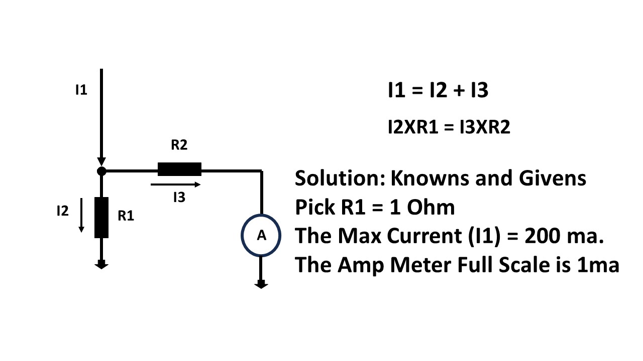
So with a bit of meter magic I am going to share how you can take a basic 0-1ma meter of old and make it read up to 200ma (or any range) for this specific application.  Enter the Meter Multiplier which is all based on simple mathematics.

Basic electronic mathematics states the current entering a node equals the current leaving a node. So for our example I1 which is the source current is the same value as the sum of I2 and I3 which are leaving the node.  Our 1st equation. 

Now by Ohms law E=IR, the voltage drop with I2 across R1 is the same value as the voltage drop with I3 and R2. They are a parallel circuit to ground starting at the same node. Our second equation: I2XR1 = I3XR2.

Now we have some other known values to finalize our solution and that is we know that the maximum current is 200ma and at that current we want our ammeter to read full scale at 1ma.

To make our life easy we pick the value of R1 to be 1 Ohm and a good reason is that at 200ma the voltage drop across R1 is only 200millivolts (0.2 volts). Another assumption is that at the full 200ma of total current that I3 will be 1ma which now sets the value of I2 at 199ma.

We are on a roll. R1 = 1 Ohms and I2 = 199milliamps so the voltage drop across R2 is also 199millivolts and with 1ma of current E=IR says that R2 is 199 Ohms. 

Now a bit of recognition that we have not addressed the internal resistance of the meter itself and we may not need to know that value. If we are supplying 200ma of current all we need to do is make R2 a trim pot and with the full 200ma of current adjust the trim pot wired as a variable resistor so that the meter reads 1ma. In essence we are taking the internal meter resistance and the adjusted R2 so that their series sum is 199 Ohms. 

So that works for 200ma. But suppose the current is only 100ma which should make the meter read half scale or  0.5ma. Does it? 

Our branching tells us the 0.5 ma is flowing past R2 and so our voltage drop is 0.0005 X 199 = 0.0995 Volts across R2 and that is the same voltage across R1. Thus 0.0995 Volts and 1 Ohm says the current is 99.5ma.Thus 99.5 + 0.5 = 100ma. QED

The quiescent bias value for the tube amp is 20ma. So how would that work. The meter scale at 1 ma indicates 200ma of current so a scaling would say the 20/200 is 1/10 of 1 or 0.1 ma on the meter scale.

Lets check that. (E=IR & we know I and R) Thus 0.0001 X 199 = 0.0199 volts. In our other branch we have 0.0199 Voltage drop and 1 Ohm which gives 19.9 ma, 19.9 + 0.1 = 20ma. QED.  

We could actually make a look up sheet that would give you an equivalent value of current as read on a 0-1ma DC ammeter.

The best for last: what we really are doing is taking the ratio of 1ma of meter current equals 200ma of circuit current. This means you take every circuit current and multiply it by 1/200 for the meter reading. That would be easy to tell you that up front but our several calculations show you the math behind that and you need to do the math to initially find the value of R2.

 I guess I have to say it or it will get missed. If you need a 0-500ma range then do the calculation of R2 for 500ma and then all values of circuit current are multiplied by 1/500 (0.002) and the circuit current is translated to a range of 0-1ma. Cool beans and slightly ahead of the innovation.

Keep in mind no Nano VNA's were used or needed for this sharing.

73's
Pete N6QW


Current Meter


10 0.05


20 0.1


20 0.1

40 0.2

50 0.25

60 0.3

70 0.35

80 0.4

90 0.45

100 0.5

110 0.55

120 0.6

130 0.65

140 0.7

150 0.75

160 0.8

170 0.85


180 0.9


190 0.95


200 1


A small test to see if you are watching this closely. I entered two values of 20ma in the Excel spreadsheet, so the tabular data is missing the 30ma value -- but the chart will tell you that. It is 4AM and I really am awake.

In case you are keeping score...

 Interesting results... Iowa : Joni Ernst's Republican seat was won by Democrat Josh Turek. [senatordb.com] , [ballotpedia.org] Kansas :...