Tuesday, February 20, 2024

February 20, 2024. Beyond Control of the Si5351

The Arduino can do more than create a stable, highly accurate VFO and BFO signal source with the Si5351. 

The real clout of the Arduino is in the control of many functions around the ham shack. Yes it can even start the coffee in the morning.


For most of the things we build the novelty size toggle switch works well. But you must be mindful of current ratings of the switch contacts. Typically those cutie pie darlings have an AC and a separate  DC rating. They are not designed to directly switch 450VDC to a tube final.

In the graphic above two MOMENTARY push button switches are used to control a 30HP motor. The switch contacts cannot directly supply power (typically 480 VAC for 30HP) to the motor but they can control the application of power to the motor.

Let us look at our circuit. The switch marked SW2 even though momentary is NC, Normally Closed. Thus, engaging that switch OPENS the circuit. The other switch, SW1 is NO, Normally Open but is also in parallel with a set of Normally Open (NO) contacts controlled by the energizing of Relay #1 (RLY1). 
 
So the sequence is that a momentary hit of SW1 engages the Relay #1  and latches that relay around SW1 and now power can be supplied to a power contactor (read very Heavy Duty relay) which turns on the motor. It may even have a step start circuit to step the power supplied, but a subject for another time. A quick hit to SW2 opens the Latch and the motor power supply gets turned off.

So what does this have to do with ham radio. Well, fans and friends (who may not be fans) I used this circuit to control the power to a 48VDC 35 amp DC power supply for a linear amp. The 12VDC went to two Hockey Pucks (Solid State Relays) that were on the primary side of the power supply. This would be especially useful if the primary of your supply was 220VAC.

The two switches were actually not switches but simulated contacts in an Arduino sketch. Watch this You Tube.


An Arduino Mega2560 was used thus many pins and lots of program headroom. The code took care of sequencing the bringing on line of the LDMOS amp and had safety features like if you hit the emergency STOP button you are forced to wait before a restart. Just enough time to stop you from smoking that $200 RF Device. It could also sense SWR, and switch in LPF's.

But why is there not more experimentation with the Arduino as a control device? This leads me to an actual story from my past work life.

I spent most of may career in aerospace but mid career I left the industry and had one of the best jobs ever. I spent almost two years working as an outside sales engineer for a distributor of automated industrial controls. I called on companies like Campbell Soup, Budweiser, and Del Monte (someday I will share about the canned peach line at Marysville, CA). The food processing industry has a lot of automation!

Got a call from Campbell Soup in Sacramento about their can line and the "missing label" detection system. As cans go down the line a label is slapped onto the can (they prefer to call it the affixing the label process). 
 
So, safe guards are built into the line to detect if a can is missing a label. The simplest form is two cat whisker probes set in the line so as cans go by if there is a label no complete circuit. No label and the circuit is completed and a bell goes off or a light goes on and a line person finds the can and puts it back through the labeling process.

Those "bastard industrial engineers" (a quote from the guy who called me) sped up the line for more throughput and it was so fast that the cat whiskers were missing cans and as their detection system wasn't fast enough and needed a settling time to complete the circuit.

I watched the process for about 10 minutes, a really good idea to understand the problem as that is on the path to the solution. There had to be a different solution other than the cat whiskers trying to detect a fast moving can

It was apparent that the detection and removal could not be done instantly. So a perfect detector is a no touch control using a proximity mode photo electric device -- well actually two. The first one is to signal "a naked can on the line" and  the second one down the line that detects it again but next to it a pneumatic ram to punch it off the line. Two steps: detect and remove which also gave you some control of the ram action that could be timed to act in concert with the line speed.

The Campbell Soup guy had a glazed look in his eyes and then said --well maybe I could just bend the cat whiskers so they would touch more can. Well that might or might not work -- but at higher speeds it will likely fail. 

The parallel here as I heard on 40M last night -- Well I would have to learn about that and it would take time. 

Some things I have done with the Arduino that don't involve the Si5351. The LDMOS Amp Control, a Remote Antenna Tuner, a Remote VFO tuner, CW sender and the Blinking Morse Code Sender to put on the beam. BTW Samuel FB Morse was first an artist and then had the idea for the telegraph after learning about electromagnets.

Susan Walker Morse (the Muse) - Samuel Morse 
Susan Walker Morse by SFB Morse
 
 
73's
Pete N6QW
 

Monday, February 19, 2024

February 19,2024. A 65 Year Perspective

 Taking Two Steps Backward.


The above chart was created several years ago when I made a presentation to a Radio Club in the UK. I updated it a bit and thought this would be a good subject for today's blog.
 
The original intent of the chart was to show the dynamic nature of our hobby and how technology has played a critical role in the box that sits in front of us at the operating table. 
 
Perhaps even that is a wrong description of today's operating position.  For instance the ARRL Radio Lab (W1HQ) has two computer screens, a Keyboard, Microphone and Key at the operating position. The hardware as such (FLEX and ICOM) are in remote racks and off to the side. 
 
Recently, I was listening in to the 40M Noontime net out here in California. They asked for check ins and a ham checking in  identifies that he is in West Virginia --- operating a remote station in Las Vegas.
 
These two examples are evidence of that dynamic shift!
 
Now you may quibble and argue that I left out rigs or my timing may be +/- two or three years but on a smoothed curve the chart tells the tale.
 
For starters we went from separate receivers and transmitters that weighed a lot. Lifting the DX-100 could cause a hernia as would a Collins R390A. Two things happened: the advent of the Transceiver with a smaller and lighter footprint. A miracle in itself but still hardware. 
 
In our last column any mods/improvements are done in software -- the same box only with changes that involved no soldering! BTW a Collins KWM-1 weighs several times the weight of the IC-7300.
 
But the real import of today rigs is capability in terms of signal processing and hearing weak signals. Then there are the (software selected) filters --different for SSB and CW with band widths that are a simple mouse click. That last piece suggests a computer inside the box. There we go -- that computer may be the size of a credit card like the Raspberry Pi Zero W (it even has Wi-Fi).
 
The chart also tells a tale about the operator, the operator skill set and the thrust of the hobby. In the early days of our hobby, the operator literally had to build everything in his station from the ground up. The hobby attracted many who were the tinkerer type. That is no longer true as the tinkering type today are but a small percentage of the total ham population.

The IARU stated several years ago that hams are hams for two reasons: Contests and Operating. Today's Radios are focused on those two aspects. You know, operating on crowded bands during a contest and of course handling all of those stations during a POTA or SOTA event.

While many express a desire to return to the tinkering aspect AND there is much cheap technology available, it just doesn't happen. The reasons are many including my own personal situation where my Caregiver activities just have no room for lighting off the iron. But perhaps the alternative is just too easy -- just buy it. That is OK.

That said that may not be entirely OK as the shack in a three-pound box also means you that you should know how it works and if it is not working properly. The tinkerer of old certainly had to know that to even get his rig on the air. But for the manufacturers -- they always say two things: Get a second back up radio and DON'T open the case -- send it back for repair!

Having been licensed for 65 years I have seen this chart 1st hand and even owned (and still own) some of those radios. My homebrew stuff certainly beats many of those built prior to 1980 especially with regard to frequency stability and accuracy. 
 
One of the significant operator requirements of the last 65 years is to learn where the reset button is located. Inextricably there are computers or micro-controller units embedded in our radio hobby. So, today's ham cannot avoid software.

The 65-year journey would not be complete without mentioning the MODE shift. In the 1950's it was AM/CW with just the dawn of SSB and those Donald Duck speaking signals. Then we had the FM and FM repeater craze. That led to Digital Communications and now the FT-8 operations using WSJTX. The newer mode forms also got a significant boost with the shift from through hole to surface mount components. Shack in a 3-pound box is here!
 
It was a most interesting exercise for me as in one chart I see many things that now created the current state of the hobby. I hoped you got a kick from seeing the evolution from a DX-100 to the IC7300.
 
73's
Pete N6QW

Sunday, February 18, 2024

February 18, 2024. We have choices.


We have a choice in what we do with our hobby! There are those who love to contest or perhaps achieving DXCC using only FT-8. Then there are those of us who like to homebrew (Radios not Beer). Still others just like to work Parks On The Air (POTA).

I have come to realize that homebrewing is a generational phenomenon. In the old days if you wanted something -- you figured out how to build it. Today if you want something it is figuring out who has the best price on the Internet. Often that jewel comes from a land afar and not here in the USA. But even then, using DHL maybe 3 days to the bench.

The generational thing is related to hardware and software where the OT's may want to stick with an LC VFO. The new generation thinks nothing of using micro python to do the task with a Raspberry Pi Pico or even a Pi Zero. I often remark that watts to antenna can come from tubes, transistors or even out of a computer, thus the tent is quite large.

As for me it is obvious I like to build things because coming from the older generation I saw things that would be really great to have -- but the technology just was not there. I shied away from building Phasing Rigs because I had an HT-37 and a GSB-100, and the phasing was always out of whack! Today we have a technology explosion of products that were once only a dream.

But what comes around goes around and although well disguised, many of I Q type SDR rigs are nothing, but phasing rigs updated to the 21st century. But as was pointed out to me by N2CQR, the I Q approach in light of DDC is akin to Brain Surgery with a Rusty Spoon. So now the jump is to DDC. BTW even though from the old school, I no longer build LC VFO's!


Choices for Today

(HB SDR Based on the ZL2CTM Design)


IC-7300

I guess for many the choice is the IC7300. But for me the HB rig signifies something besides a shiny small box with a waterfall. The HB rig takes advantage of the new technology and requires skills beyond pushing the Buy It Now button. Plus, there is no finer joy than to be able to say that the rig on this end is homebrew. 
 
It all comes down to WYKSYCDS.
 
73's
Pete N6QW


Saturday, February 17, 2024

February 17, 2024. The Data Tells You Much.

Yesterday's posting was the lowest viewed blog posting all year. So, that tells me much about my blog reading audience. What I thought may be technically cool, in this instance fell way short of the mark. So, I will not bore you any further with the project: SDR Without A Computer. But long ago I learned even negative information is good information. 

One of my published projects, in SPRAT, the MC1496 Direct Conversion Receiver has the distinction of having received the most requests for the Arduino Code (nearing 200). That is telling in that the technical level of the projects has to be within the grasp of many hams who are not EE's or come from a technical background. 

I must remind myself that this is just a hobby. So, I guess my sharing has to be in the realm of simple projects, LC VFO's, plug and play kits with circuit boards and detailed parts lists complete with BOM's. Got it.

While at the Board and Care Home with the XYL, we have been watching a lot of TV. Netflix has a series called Extreme Home Makeover with Ty Pennington. Aside from the very sad stories that end in a better way, the building of a complete home in one week is astounding. It can be done, but there is much behind the scenes pre-fabrication and the all-important critical path job sequencing. (Yes, I did that for a living at one time.)

But from that TV show plus a tour through my extensive junk box, shelf of shame and projects that sort of worked, kind of worked or never worked sprang the kernel for today's blog post.

Below is my previous attempt to build a 4X6 single board SSB Transceiver Kernel. We have the RX/TX Mixer (TUF-1), the IF stage with 2 DGM's, the Balanced Modulator/Product Detector using the ADE-1, the Mic Amp (NE5534) and an Audio Amp (2N3904 & LM386). The Filter matching transformers are missing a sign of parts cannibalization. 


There must have been an OLED display in the build as I note the use of a 2N3904 power supply conditioner feeding the LM 386 audio amp. (Top Center of the Board -- three parts and it cleans up noise on the rail.) 

Also of note, the use of diode steering on the DGM's for bidirectional operation. That was an earlier post on this blog. There is also a fixed 8VDC bias supplied to Gate 2 on the DGM's and two small Green LED's that change brightness with signal peaks. This diode steering circuit is from G4GXO.

There is a relay that likely is a part of the TR circuitry. I even spotted a 2-pin header that was once used to unbalance an SBL-1 that was installed before the ADE-1 was retrofitted into the board. I have no recollection as to why this board is in the state that now exists. The filter is missing and that perhaps is a sign of a repurposing, or possibly suffered from the dreaded Dishal Diarrhea.

Of note: No Bitx circuits, No EMRFD, No TIA and No Facebook Groups influence. Not shown is the Band Pass Filter, Rx RF amplifier/Pre-Driver, the Driver and Final Amplifier Stage with LPF or the Digital LO/BFO (possible Seeed Xiao RP2040). Funny how these have all been covered in posts this year.

So, our goal is to Make Over this derelict and forlorn SSB Transceiver Board.  Hopefully this may have more appeal than yesterday's posting. Yes, for those who are Digital LO adverse this will work with a LC VFO, homebrew filter (which was on the board originally) and a well shielded external Crystal BFO.

This may have more appeal to you the blog readers, as you follow along versus the earlier posting SDR.

73's
Pete N6QW

PS. I did receive one piece of feedback from the Valentines Day posting about the guy who gave his wife an oil change in lieu of candies for that special day. I am only sharing what he said as a follow on to the oil change. "It will be a long time before he gets her in to the rack for any routine preventive maintenance!" I don't write these -- just sharing.

Friday, February 16, 2024

February 16, 2024. SDR WIithout a Computer a Proposal.

Hopefully the masthead title has caused a quiver in your mouse hand. So, scroll on.

That was sure easy to get your attention for at least 2 Milli-microseconds (2 nanoseconds)!

In response to yesterday's posting and so not to disappoint you there is a way to generate USB, LSB and CW signals without using a Crystal Filter or a Computer. 
 
My proposal will use a Micro-controller unit, but not a computer! You can select bandwidths for the signals but that totally involves all hardware so N2CQR might call this a Hardware Defined Radio (HDR). 


So OK, I am dancing around the subject of Phasing type Receivers, Transmitters and Transceivers. The I/Q approach for SDR uses a Phasing Method to generate SSB and CW signals, but the computer does the heavy lifting for the generation and decoding of the signals. 
 
Notionally think of the I Channel as the output from Balanced Modulator #1 and the Q Channel as the output from Balanced Modulator #2.

Essentially a Phasing approach as shown in the block diagram above all depends on mathematics (you know that sine and cosine stuff). Two components (Audio and RF) are developed so that two signal streams are created for each that are exactly the same, but 90 degrees out of phase. Thus, two exactly the same Audio Streams 90 degrees out of Phase and the same for the RF (LO) signals. The term I and Q stands for In Phase and Quadrature. 

Two mixer stages combine the RF and Audio signals to create an I and Q channel. If you reverse the Audio channel inputs, it reverses the sideband. (This is how it was done back in the early days of Phasing.) This affords us a simple way to change sidebands. 
 
The outputs of the ADE-1's can be combined in a simple ferrite core transformer. Unbalancing one of the Balanced Modulators can put you on the road to CW.

Getting back to Sideband reversal. In a SDR rig I built using a couple of ADE-1's, you got automatic reversal on transmit. I fixed that problem with a double pole double throw relay so that you got the same sideband in Rx and Tx. It wasn't until much later when I was looking at the QUISK software -- you can make that happen with the software and no need for the relay. RTFM.

The Phasing approach was at the leading edge of SSB rigs ahead of crystal filters but were prone to drift (think vacuum tubes, plus heat and 20% TOLERANCE components) and the really Big Elephant in the room -- the operator had to know how to adjust the controls. So, that soon gave way to the Crystal Filter method -- an early on plug and play concept. 
 
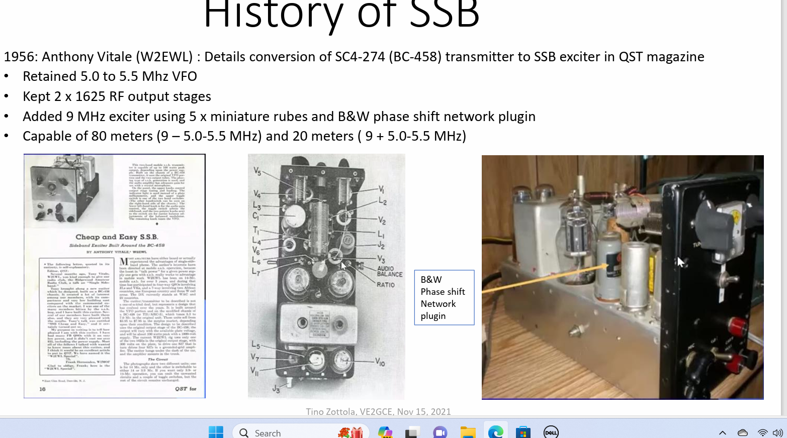
A very famous Phasing rig was built from a converted ARC-5, BC-458 transmitter -- Thank You, Anthony Vitale, W2EWL (SK)! Many were heard on the air, and he ran his rig mobile!


Another of the popular homebrew Phasing SSB transmitter was from the GE Ham News, known as the SSB Jr. Hallicrafters also in the fray produced the HT-37 and HT-44 both Phasing transmitters and no OT could forget the Central Electronics 10a, 10B, 20A and 20B, that also sported FM and AM in addition to SSB and CW. Heathkit even built an adapter to generate Phasing SSB for their AM/CW transmitters, AKA the SB10.
 

Think Heat and +/- 20% Components! 
Note the DPDT switch for USB/LSB
Search on N4TRB for copies of GE Ham News
 
Is should be clear that SDR is nothing more than these old designs reincarnated using a computer and more stable components.

Several years ago, I Kludged a way to create a SDR Transceiver using a couple of ADE-1's, a computer sound card, a combiner network and an LO (at 4X) controlled by the software to work with various software programs. Of course, you needed a computer like the Raspberry Pi3 or a Windows machine for the software and control.
 
RADIG #2 The Relay center left to fix sideband reversal on Transmit.

But now with being able to get the KK7B Audio Phase Shift Network to work and my newly created Seeed Xiao, RP4020 Quadrature LO, the stars are aligning and they line up for an answer to yesterday's question.

The approach I am suggesting is my RADIG #2 ADE-1 Board coupled with a Phased Audio Generator (not unlike KK7B's T2 Transmitter) and a Phased LO based on the Seeed Xiao RP2040 with code I embellished from work by W9RAN. We have the block diagram, and we have the hardware blocks thus the open item  finding some time time to get soldering.
 
The Line IN is the Phased Audio Signal in the transmit mode. The Line OUT would be a Phased Audio Network in the Receive Mode. Such Audio Phase Shift Networks exist, and I have built several. 
 
The audio phasing network can be tailored using a free software package called Quad Net. With this package you can pick the granularity of 90-degree phase shift accuracy over a range of audio frequencies as well as the bandwidth of the audio range. The "tightness' and degree of opposite side band suppression is set by the component values generated by the software. 

The caps are held to a standard value (say 0.01uF) with a small tolerance (1% and the really tight networks use 0.1%). There is a huge difference in unit price. Thus, the variable is the resistors in the network which are non-standard. The software lets you pick a tolerance range like 1%, 5% and 0.25% or the as computed value. I looked at 0.25% resistors and found all of them for an 8-pole network. The glitch -- 5000-piece buys at 3 cents each is the only option. An 8-pole network with very close tolerance resistors can give you near 60dB of suppression with a small phase angle error over the voice range.


The 8 pole phasing networks from Quad Net


With just 8 devices the Suppression Curve is impressive. At worst case (200 and 2.7kHz) the suppression is 48dB and 53dB with 58dB mid-range. The mid-range rivals many Crystal Filters and you never have to worry about Dishal Dystopia, matching crystals and using your Nano VNA.
 
There are always those skeptics who want to know the source of any programs or applications. Quad Net comes from Jim Tonne, the guy who developed the Elsie program,  the basis for the W3NQN LPF Design. So it is real stuff and has street creds.

The design is for 8 Poles with 1% resistors and Capacitors and those that are unmarked are 10K. I selected the NE5534 low noise op amp as the device of choice and about $60 will buy all of the parts for TWO boards and the design software can be spit out as a modulator or de-modulator. By all of the parts, the sockets are included. All the parts less the NE5534s,  are 0805 surface mount. But wait, I designed a PC Board to use with the SMD parts and if you have a $200 CNC you can make this at home.


Send me an email to my QRZ.com email address if you want the .dxf file to cut this board. I like my design (why of course I do, it is mine) because it is a universal board in that you can build just what you need like a 2 pole through 8 pole. The software pretty much leads you to a 8 pole and on the cheap a 6 pole.
 
 You might want to start small and just build the KK7B T2 board as shown below (6 Pole).
 

 6 Pole as in the Rick Campbell T2 Transmitter.


Now the ADE-1 stage is inherently bi-directional and the LO simply supplies 90 degrees out of phase RF. The Audio Phasing network can be bi-directional but for the ease of construction two such networks would be built for a transceiver, one for Rx and one for Tx.


If you have a Digital Storage Oscilloscope you can set it up for an XY plot function (Lissajous Figures) and look at how good is the audio phase shift at various frequencies.

Here we have a plot at 1.6kHz of a quadrature sine wave run through a 6 Pole and if we had a PERFECT 90-degree shift, we would have that "perfect circle" on the screen. Not perfect but sort of on the OK side.

This is using the KK7B Design ala T2!


Recently I was successful in writing a sketch for a 90 Degree Phase shift LO for the Seeed Xiao, RP2040 and the Si5351. The CLK0 and CLK2 outputs are square waves and so with 90 Degrees you get a rectangular pattern versus the circle. BTW that LO is on 10 Meters (32MHz)!


This is a lot to sink in but the hard pieces like the Audio Phase Shift Network, the Mixer Stages and the Quadrature LO exist. So you could start with something beyond a clean sheet of paper. 

Other bits like a steerable Rx RF Amp and Tx Pre-Driver exist as does an Audio Amp, Driver Stage, LPF/BPF and the Final RF Amp. These are all modules that have been described on this blog. The long time Huge Stumbling Block the Quadrature LO has been conquered and that too exits.

There, is your mouse hand still quivering? In case you haven't noticed I did not turn on my soldering iron as a 1st step, and my two Nano VNA's rest silently, gathering dust in their shipping boxes. It is all about the Noodling design process.

73's
Pete N6QW
 

Thursday, February 15, 2024

February 15, 2024. A Thought Piece?

How would you create a SDR type transceiver without using a computer. Is that really possible to do?

I won't put you on the spot and expect any answers, but it does raise the specter of a better, well maybe not better but alternative mouse trap. 
 
Many rodent traps simply kill the rodent either with poison or by mechanical means. Then there are the kinder, more gentler approaches such as trapping the vermin and releasing same in your neighbor's yard. A gift to your obnoxious, loud, uncaring and self-indulgent next-door neighbor. (Remember my Italian heritage -- we don't get mad we get even!)

Iowa Hills Software ~ 100 Coefficients 3.75kHz Fc and 2.5 kHz Wide
The ZL2CTM Teensy SDR.  If I don't post a picture then no views.


Over the past several years I have repeatedly asked myself that question initially posed. Now with a tip of the cap to Charlie Morris, ZL1CTM, he did create a SSB transceiver using the Teensy Micro-Controller Unit and the companion audio board. The Teensy has embedded in the code the Hilbert Transforms with the Iowa Hills Filter constants (see 1st Chart). Yes, this was all done inside the Teensy (available from PJRC and sold from the USA).
 

In fact, I built two versions of Charlie's design, but I could not get the two rigs to have significant opposite sideband suppression on both receive and transmit. On Receive, it was really obvious on very strong signals. Reports from QSO's told me my signal was more DSB than SSB.

I firmly believe it was a problem on my end and not with Charlie's design. I did battle with the Iowa Hills software to get a narrower filter than the stock code that was in his design. I think that is the issue with the two I built.

So that certainly would be one way although I would need to really roll up my sleeves and figure out exactly what I did wrong in the code. For those who are software adverse and loathe to follow detailed programming nuances -- don't even start.

Then there are the uSDX radios that are being sold by the hundreds (maybe thousands) on eBay and Amazon. I scratch built one starting with just the plain circuit board. 
 
My build was a flat out a piece of crap on both transmitting and receiving. Even some You Tube videos from other builders early on, showed the naked truth about use on SSB. On CW it might have been OK but not SSB. It was so bad that I did not even place it on the Shame Shelf. 
 
In my opinion the Arduino is ill suited for the job! The Xiao RP2040 might have enough large sized cojones to do it with its 8X faster processor and 2MB of program storage However, I will forever forget that track.


So, put on your thinking caps and conduct an omphaloskepsis process about some simple way to do it. There has to be a better mousetrap out there!

73's
Pete N6QW

The Risk of Power.

 What happens when the faithful lose faith? We don't know the result but now it is time to pop more popcorn as the interesting part of t...