Hopefully the masthead title has caused a quiver in your mouse hand. So, scroll on.
That was sure easy to get your attention for at least 2 Milli-microseconds (2 nanoseconds)!
In response to yesterday's posting and so not to disappoint you there is a way to generate USB, LSB and CW signals without using a Crystal Filter or a Computer.
My proposal will use a Micro-controller unit, but not a computer! You can select bandwidths for the signals but that totally involves all hardware so N2CQR might call this a Hardware Defined Radio (HDR).

So OK, I am dancing around the subject of Phasing type Receivers, Transmitters and Transceivers. The I/Q approach for SDR uses a Phasing Method to generate SSB and CW signals, but the computer does the heavy lifting for the generation and decoding of the signals.
Notionally think of the I Channel as the output from Balanced Modulator #1 and the Q Channel as the output from Balanced Modulator #2.
Essentially a Phasing approach as shown in the block diagram above all depends on mathematics (you know that sine and cosine stuff). Two components (Audio and RF) are developed so that two signal streams are created for each that are exactly the same, but 90 degrees out of phase. Thus, two exactly the same Audio Streams 90 degrees out of Phase and the same for the RF (LO) signals. The term I and Q stands for In Phase and Quadrature.
Two mixer stages combine the RF and Audio signals to create an I and Q channel. If you reverse the Audio channel inputs, it reverses the sideband. (This is how it was done back in the early days of Phasing.) This affords us a simple way to change sidebands.
The outputs of the ADE-1's can be combined in a simple ferrite core transformer. Unbalancing one of the Balanced Modulators can put you on the road to CW.
Getting back to Sideband reversal. In a SDR rig I built using a couple of ADE-1's, you got automatic reversal on transmit. I fixed that problem with a double pole double throw relay so that you got the same sideband in Rx and Tx. It wasn't until much later when I was looking at the QUISK software -- you can make that happen with the software and no need for the relay. RTFM.
The Phasing approach was at the leading edge of SSB rigs ahead of crystal filters but were prone to drift (think vacuum tubes, plus heat and 20% TOLERANCE components) and the really Big Elephant in the room -- the operator had to know how to adjust the controls. So, that soon gave way to the Crystal Filter method -- an early on plug and play concept.
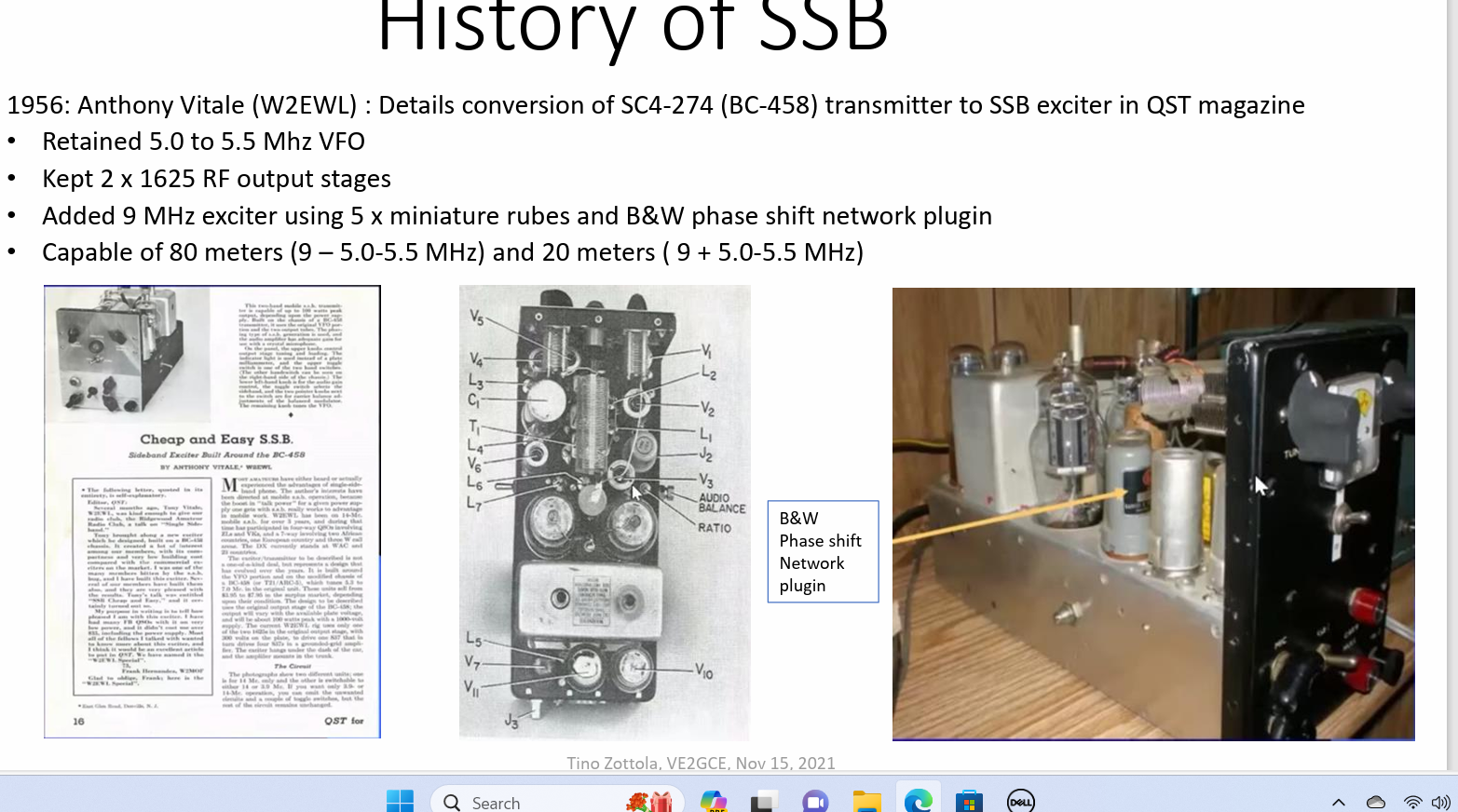
A very famous Phasing rig was built from a converted ARC-5, BC-458 transmitter -- Thank You, Anthony Vitale, W2EWL (SK)! Many were heard on the air, and he ran his rig mobile!
Another of the popular homebrew Phasing SSB transmitter was from the GE Ham News, known as the SSB Jr. Hallicrafters also in the fray produced the HT-37 and HT-44 both Phasing transmitters and no OT could forget the Central Electronics 10a, 10B, 20A and 20B, that also sported FM and AM in addition to SSB and CW. Heathkit even built an adapter to generate Phasing SSB for their AM/CW transmitters, AKA the SB10.

Think Heat and +/- 20% Components!
Note the DPDT switch for USB/LSB
Search on N4TRB for copies of GE Ham News
Is should be clear that SDR is nothing more than these old designs reincarnated using a computer and more stable components.
Several years ago, I Kludged a way to create a SDR Transceiver using a couple of ADE-1's, a computer sound card, a combiner network and an LO (at 4X) controlled by the software to work with various software programs. Of course, you needed a computer like the Raspberry Pi3 or a Windows machine for the software and control.

But now with being able to get the KK7B Audio Phase Shift Network to work and my newly created Seeed Xiao, RP4020 Quadrature LO, the stars are aligning and they line up for an answer to yesterday's question.
The approach I am suggesting is my RADIG #2 ADE-1 Board coupled with a Phased Audio Generator (not unlike KK7B's T2 Transmitter) and a Phased LO based on the Seeed Xiao RP2040 with code I embellished from work by W9RAN. We have the block diagram, and we have the hardware blocks thus the open item finding some time time to get soldering.
The Line IN is the Phased Audio Signal in the transmit mode. The Line OUT would be a Phased Audio Network in the Receive Mode. Such Audio Phase Shift Networks exist, and I have built several.
The
audio phasing network can be tailored using a free software package
called Quad Net. With this package you can pick the granularity of
90-degree phase shift accuracy over a range of audio frequencies as well
as the bandwidth of the audio range. The "tightness' and degree of
opposite side band suppression is set by the component values generated
by the software.
The
caps are held to a standard value (say 0.01uF) with a small tolerance (1%
and the really tight networks use 0.1%). There is a huge difference in
unit price. Thus, the variable is the resistors in the network which are
non-standard. The software lets you pick a tolerance range like 1%, 5%
and 0.25% or the as computed value. I looked at 0.25% resistors and
found all of them for an 8-pole network. The glitch -- 5000-piece buys
at 3 cents each is the only option. An 8-pole network with very close
tolerance resistors can give you near 60dB of suppression with a small phase
angle error over the voice range.


The 8 pole phasing networks from Quad Net
With just 8 devices the Suppression Curve is impressive. At worst case (200 and 2.7kHz) the suppression is 48dB and 53dB with 58dB mid-range. The mid-range rivals many Crystal Filters and you never have to worry about Dishal Dystopia, matching crystals and using your Nano VNA.
There are always those skeptics who want to know the source of any programs or applications. Quad Net comes from Jim Tonne, the guy who developed the Elsie program, the basis for the W3NQN LPF Design. So it is real stuff and has street creds.
The design is for 8 Poles with 1% resistors and Capacitors and those that are unmarked are 10K. I selected the NE5534 low noise op amp as the device of choice and about $60 will buy all of the parts for TWO boards and the design software can be spit out as a modulator or de-modulator. By all of the parts, the sockets are included. All the parts less the NE5534s, are 0805 surface mount. But wait, I designed a PC Board to use with the SMD parts and if you have a $200 CNC you can make this at home.

Send me an email to my QRZ.com email address if you want the .dxf file to cut this board. I like my design (why of course I do, it is mine) because it is a universal board in that you can build just what you need like a 2 pole through 8 pole. The software pretty much leads you to a 8 pole and on the cheap a 6 pole.
You might want to start small and just build the KK7B T2 board as shown below (6 Pole).


6 Pole as in the Rick Campbell T2 Transmitter.
Now the ADE-1 stage is inherently bi-directional and the LO simply supplies 90 degrees out of phase RF. The Audio Phasing network can be bi-directional but for the ease of construction two such networks would be built for a transceiver, one for Rx and one for Tx.
If you have a Digital Storage Oscilloscope you can set it up for an XY plot function (Lissajous Figures) and look at how good is the audio phase shift at various frequencies.
Here we have a plot at 1.6kHz of a quadrature sine wave run through a 6 Pole and if we had a PERFECT 90-degree shift, we would have that "perfect circle" on the screen. Not perfect but sort of on the OK side.

This is using the KK7B Design ala T2!
Recently I was successful in writing a sketch for a 90 Degree Phase shift LO for the Seeed Xiao, RP2040 and the Si5351. The CLK0 and CLK2 outputs are square waves and so with 90 Degrees you get a rectangular pattern versus the circle. BTW that LO is on 10 Meters (32MHz)!

This is a lot to sink in but the hard pieces like the Audio Phase Shift Network, the Mixer Stages and the Quadrature LO exist. So you could start with something beyond a clean sheet of paper.
Other bits like a steerable Rx RF Amp and Tx Pre-Driver exist as does an Audio Amp, Driver Stage, LPF/BPF and the Final RF Amp. These are all modules that have been described on this blog. The long time Huge Stumbling Block the Quadrature LO has been conquered and that too exits.
There, is your mouse hand still quivering? In case you haven't noticed I did not turn on my soldering iron as a 1st step, and my two Nano VNA's rest silently, gathering dust in their shipping boxes. It is all about the Noodling design process.
73's
Pete N6QW


