Simple -- it is 75 years worth of time and world indifference. Get out and vote or the next photo will have Godless Zombies in charge.
The Emperor should be very careful what he says about Locking People Up. Karma is a bitch and it will be interesting to see what plays out.
73's
Pete N6QW
October 13, 2020
Update on my uSDX Transceiver project.
I found the project interesting and has a lot of inbred creativity. That said I have not been successful in achieving a quality output signal in SSB. I am perhaps not alone and for those who have given glowing reports of 5X9 signals with amazing audio, there are two explanations.
The first is that they are smoking some of that funny stuff that is a major cash crop here on the left coast and/or the second they have no clue of what a good quality SSB signals should sound like.
My signal quality on Transmit is distorted, it is wideband and the opposite sideband suppression is not evident. I think the FCC under normal times would question my using this project to transmit SSB.
Knowing what I know today I would not have even begun to build that radio. So if you are thinking about proceeding then think again long and hard before jumping on board. Read all the threads about Transmitting SSB (which by the way I was the 1st to post that inquiry).
Here is a way to think about the uSDX...
It is sort of like the Fan Dancer of the 1930's who has
the audience on the edge of their seats with her tantalizing moves and then
they discover “she” is not a woman.
At Best the uSDX in my opinion is a "Wanna Be" SSB Transceiver! Perhaps never to be!
73's
Pete N6QW
***********************
October 12, 2020
Christopher Columbus Day ~ That Italian Dude that Discovered America.
Since I had time I worked on the Balanced Modulator and Microphone Amp Board for #50. It was a bit of a challenge to fit all the electronics on the one piece of scrap board I had --but we made it.
Along the left side is the 2N3904 Microphone amp and toward the right side is the MC1496 Balanced Modulator. The Black Trimmer is the mic gain and the White is the Balance Pot.
BTW -- using the single sided copper vector board -- there is only one wire that is crossed over. This is where tribal knowledge and lots of skill enable one to make high quality PC Boards. It is the yellow wire that supplies power to the 3 K resistor connected to Pin 12 on the MC1496. That connection serves as an anchor point for providing source power to the board during transmit. Because of my expert skills at layout it is also a common power source point for the microphone amplifier. Ya got to say it: Nice Board!
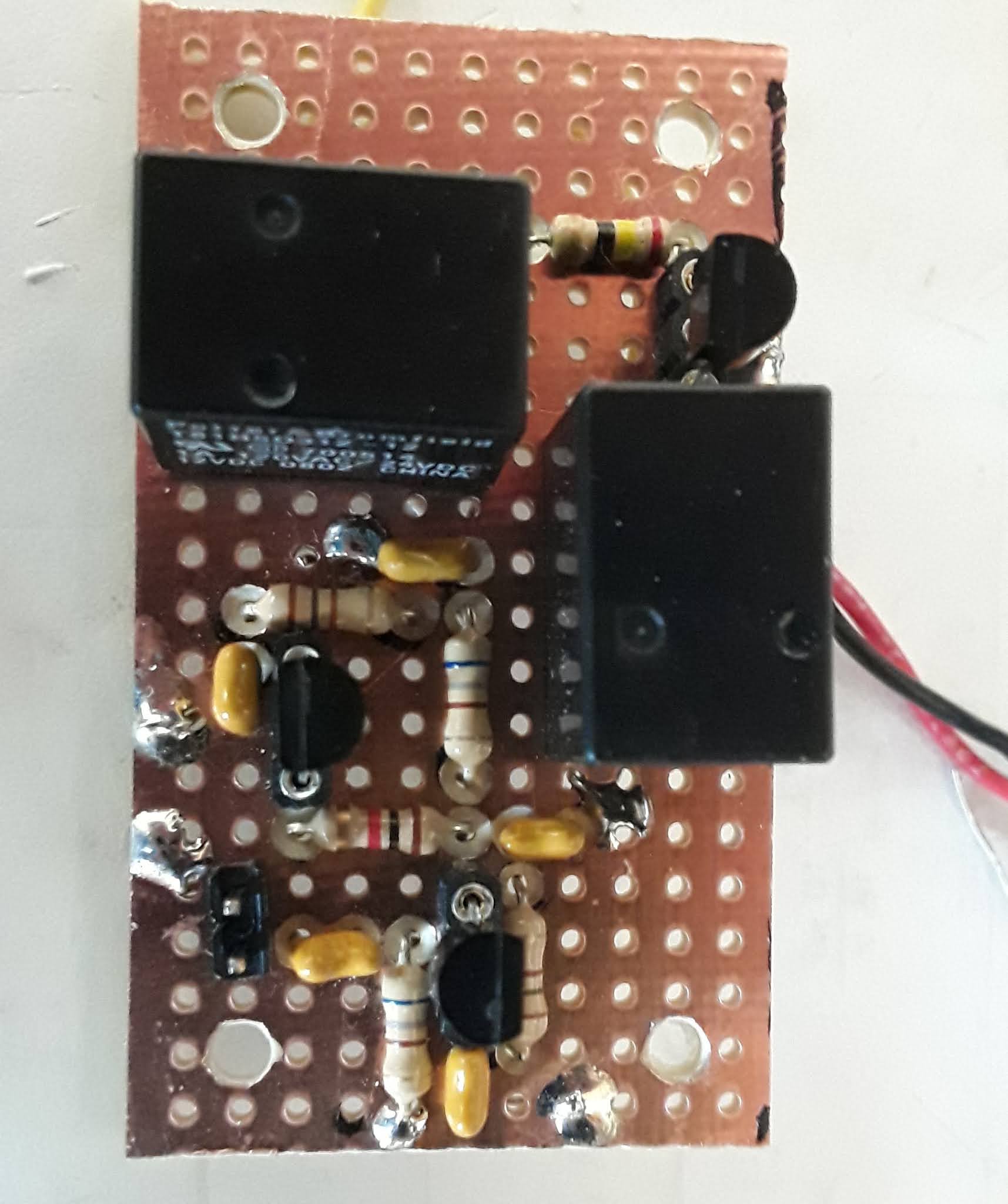
Above is the Plessey circuit that includes the Bi-Lateral 2N3906/2N3904 Amp stages and the two Relays, plus 8 VDC Voltage Regulator. The 2N3906 is used as the Receiver RF Amplifier Stage and the 2N3904 as the Transmit Pre-Driver (Bottom Transistor). The relay along the right hand edge is used to route the signals to the Plessey Stage from the Antenna (on Receive) to the Transmit Linear Amplifier stages (on Transmit).
The relay at the top normally has the two 100 Ohm Emitter resistors connected to 8 VDC (On Receive) which means the 2N3906 is active and the signals pass from the Right (Antenna) through the relay, amplified and to the Left (and on to theBPF). When this top relay is engaged (On Transmit) then both 100 Ohm Emitter Resistors are grounded. This now makes the 2N3904 active so that RF passes from the BPF (Left) is amplified and then routed to the follow on Transmit stages through the relay on the right hand edge.
Test Time Tomorrow. The SCW is taking a life form.
73's
Pete N6QW
My #49, a kit no less, has proven to be a huge disappointment to me! I think it is an uneven playing field; but in time we shall see.
With such a disappointment you are left to having to chose between drowning myself in Italian comfort food or building another transceiver -- it was an easy choice --- BOTH.
About a month ago (three transceivers ago) I built a Direct Conversion Receiver using the MC1496. It has worked well and God willing will be formally published. All I can say is if you want the article and details then you best be a member of the G-QRP Club!
As well as that DCR worked you have the annoying problem of the opposite sideband. It drove me nuts -- I know of course how to rid yourself what you don't want. Thus was born the idea of a Bilateral IF Module. Now I had some junk boards that contained a Homebrew Double Balanced Mixer. JIC you can search youtube and you will see three videos of how to do that from N6QW (me). That same board contained a 3 Pole Crystal Filter Operating at 12.096 MHz
There were some other former circuits on that board that I simply ripped off with an 80 Watt Radio Shack Soldering Iron operating at 500 C. I was left with just the DBM and the 3 Pole filter. I had a another small sub-board that had one of those marvelous Plessey Amps installed complete with a microminiature switching relay. I could solder this board to the DBM/Filter Board. With a piece of scrap Single Sided Copper Vector Board I built a second Plessey Amp.
So the circuit is an input from the RF Amp (2N3906) and the BPF to the DBM. The LO ( operating at either 19 MHz or 5 MHz for the sideband switching) on to the 1st Plessey Amp and thence through the Filter on to the 2nd Plessey Amp. From that Board on to the MC1496 as the IF input and the LO originally to the MC1496 was now swapped for a BFO operating at 12.096200 MHz.
Hey Mitch McConnell it is perfectly OK to visit the White House -- the President got the miracle cure from God! See he was sick and got well so quickly! The emperor (with the small e) says everyone can get his cure. Be NOT Afraid!
SSB Tests of the uSDX ~ Real Awful!
Using my HB RADIG I listened to the uSDX transmitting into a dummy load. The signal was terrible! I think there maybe a board/firmware issue. The second half of the video was run to show my HB SDR is working and copying good quality signals.
My uSDX board is not ready for Prime Time. BTW I also note that SSB receive is not as good as my RADIG. Are there issues with the V1.02 Board?
Those who have reported amazing results on SSB (receive and transmit) seem to be using something other than the V1.02 -- they are using a modified QCX board (I believe that to be true). Is there a clue there? I may have misstated something; but that does appear to be the case.
Caution is a good word when entertaining building a uSDX. Since I am uninterested in CW and the SSB implementation appears doubtful using the uSDX Board I have, that readers is the basis of my caution. But there are other boards and other approaches so don't give up. The price point may be too good to be true and so Caveat Emptor!
73's
Pete N6QW
If you think the last 9 months has forever changed our hobby -- just wait. The Covid19 Pandemic not unlike the Black Plague several centuries ago is a driving force for innovation. When one is stuck in the shack (SITS --Thanks N2CQR for that innovation), often this forces us to think out of the box and to apply solutions to problems that previously were not investigated. It is being done now --because we are forced by Covid19 to think creatively.
BTW for those who are not students of history --two Black Plague innovations very much impact our beloved hobby on a daily basis. (Calculus and Logarithms )
Advancements in SDR technology has propelled the use of single board computers and microcontrollers as embeds in our ham rigs. We now can tell the other station that they are off frequency by 20 Hertz, since we can visually see that actual aberration using a $35 computer. Today we have a SDR Transceiver using a $2 Microcontroller. True some of these are in the teething stages and have ugly warts; but so was the Bitx20 and the uBitx. But with the internet as the glue --soon group solutions evolve and we are all the better for it.
As China gears back up to be the world supplier beyond electronic parts; but more sophisticated sub-assemblies and full assembles, the price points will shift downward and we benefit. Shifts in the supply chain delivery processes now puts parts in your hand on Sunday! I got two such deliveries this past Sunday!
Just listen to the makes of the "appliance boxes" on the air and the vast majority are SDR based --they have to be for the ham consumer demands the very latest in technological whiz banging. The newest homebrew stuff is on a similar course, whether you have rolled your own or now engaging in the uSDX craze -- SDR is minimalist on hardware and the maximum on capabilities.
Also impactful are low cost complete sub-assemblies such as the Si5351 three PLL clock breakout board. Recently I saw an advertisement for Three for $10! A similar ad (Three for $10) for the Arduino Nano -- now gives you three digital VFO's for a $20 Bill.
But also be aware that SDR is forcing some electronic goodies to "self remove" the products from the scene. Commercial Crystal Filters will likely disappear from the market square and now you are denigrated into building one. Given the choice of homebrewing a filter or the alternative technology, the SDR done in software, with multiple selectable filter bandwidths, quite quickly becomes a much better alternative.
So in the remaining 90 days in addition to having a new President here in the US, it is time to invest in becoming fluent in the core SDR principles. The year 2021 will be even bigger than 2020 insofar as the new technology as now the last year's technology will become this years new hardware.
Time to clean the shack and rid yourself of those old analogue parts and make room for the new Digi-SDR gear.
73's
Pete N6QW
Vote! The voting process has officially started here in CA.
The title regarding a Handful of Dynamite is most appropriate today October 5th, 2020. Up until today I had not had the transmitter working other than to discover it would only put out about 250 milliwatts. It is appropriate in that if I had some dynamite I probably would know where to stick it (get it: a stick of dynamite).
There is an overly discussed Q5 Modification where you completely short out this transistor and remove a 100K resistor (R28). This now pops the output to close to 5 watts. That was a huge improvement in RF output.
But all is not well in OZ! When you key the transmitter you get and small RF output and then a significant output on voice peaks. But the output with no modulation is like in a Filter Rig when the carrier is not fully balanced out or when you have the bias level set too high on the IRF510.
In the menus for the uSDX there are three transmit adjustments you can make and they are : Tx Gain (nominally set at 4) and a Minimum bias setting (nominally set at 40) and a Maximum bias setting (nominally set to 140). I set all of those parameters prior to the first transmitter tests. When I saw the RF output with no modulation adjusting those did make some change but it did not make the reading go to zero!
BUT the real problem on transmit is that the signal sounds terrible! Adjusting those three parameters so that the RF out with no modulation is reduced, simply exacerbates the bad sounding signal at the nominal settings. I have to read up on the thousands of posts to see if this has been fixed.
But I did find that on CW not so much of an issue because there is a simple on off. If you set up operation for VOX--then there is only signal out when you speak which eliminates the RF out with no modulation.
BUT AGAIN Even with VOX --it sounds like crap! The uSDX probably OK for CW but with what I have now I would not use it on SSB until this issue is resolved!
I will now spend time researching the postings and documentation to see if it can be cleared up. Class E used on SSB maybe is like putting a supercharger on VW Beetle --still a VW! I am disappointed --where is that stick?
73's
Pete, N6QW
Today I had a chance to exercise the uSDX in receive and was impressed at how well it hears and the built in functionality. I only got it working on the receive this morning and still think there is an issue with the microphone jack -- it may be internally shorted and was always showing being in transmit before unsoldering.
Unsoldering the jack from the board made it work and if you plug in a microphone -- without touching the PTT it is in transmit. A clue here. So I need to order and new jack (maybe two). I will also order a high quality Bourns Encoder and better tactile PB switches. Also need to get some 4" long M-F jumper cables. This will then give me the option of having a front panel.
A lot of posts about having trouble with transmitting --so before I do any transmitting I need to find the setup for transmit and then create a cheat sheet on all of the settings (like the bias settings). I have only built one LPF and I ran short of T-37-6 cores. I have all of the caps for four bands but not enough cores. So the next band will be 20 Meters. So a little more money to be spent at W8DIZ.
You want SDR -- then get a uSDX. If you crave a waterfall get connected to the webSDR sites and you can have waterfalls until the cows come home.
This morning I touched up the solder joints on the encoder and the switches. Boom now working on receive!
BUT THIS IS WHERE I WAS LATE YESTERDAY. Still food for thought about the encoder, switches and display...
I received the missing parts installed same including the new firmware and #49 is best described as a crystal set with only 5 feet of wire attached! I have three ATMEGA 328 microcontrollers that have the very latest firmware installed and the condition is exactly the same with any of the controllers in the radio. I do get some of the functionality so I know the code has been loaded on the 328's.
My belief is that there is a hardware issue other than the 328 quite possibly in the encoder and the push button switches. Here is the issue --the radio does not respond to the command inputs. This is a menu operated radio and it is difficult to get the radio to respond to command inputs. There have been some guides published on how to navigate the menus -- but this radio is much like a small child who ignores instructions and inputs (Maybe like our emperor. See wearing a mask is important!). See the guide below the photo.
Turn the encoder and nothing changes on the display; but going through some other button pushing you realize the frequency has changed as a new value will show up but you hear nothing. It did work once and I heard a 40M station quite well -- but never again did it work. This lends a weight of evidence to some hardware issue.
Others have their uSDX perking right along -- but alas mine is a like a lump of coal that has not been ignited -- no warmth, no light, no glow. I think I will just move away from it for a period of time as I am fresh out of ideas.
Here are a couple of things I would do different knowing what I know now. I would (like I saw in one set of constructor photos) dump the cheap detent encoder and the flimsy push buttons and hardwire in a better encoder and switches mounted on a panel. I would also remote the display on that same panel. With the display as a plug in the board -- hard to view. I am not so much interested in a compact radio as I am one that works and has decent hardware.
Yes Virginia, this is the early stages of a uSDX build. I was shorted some parts by Digi-Key and so had to order from Mouser. Thus I am not done! I also need to build the LPF's and have parts coming for those too.
The build is pretty simple but you have to know some stuff to do this stuff. Example, there are twelve 100nF caps to be installed. I looked over the board and found all 12 locations. While I was doing the hunting, I wrote down on a my construction notes the twelve part ID's like C1, C13. Then as I installed the part, double checking the silk screen with the value, I marked it off the listing. Once I got through the list I checked all twelve were marked off and double verified that I indeed installed the right part value at the right location.
There was a problem with Spurs which has been resolved by Guido PE1NNZ and new Firmware is available for download It is V1.021.
The only thing aside from not having all of the parts yet being able to run the ATMEGA 328 is the crazy menu's. On boot up there are 9 sections with sub menu's in those section such as MODE (USB default, LSB,CW) or Band (40M default). The problem I have been having it seems a mystery once in the section --how to make changes. You essentially have four controls. The encoder which has two -- the encoder tuning and the PB control and then there are two Momentary PB switches. At times I have been able to change bands or change modes but no idea how I did it. The four controls interact but not intuitive what they do. This was designed by a software guy! Have pity on us hardware freaks! Must be a fault on my part as I don't own and ICOM 7300 thus not used to menu stuff.
There is an issue with the ATMEGA 328 purchased from Digi-Key. It is as dumb as a rock as it lacks the Boot Loader. So you have to Jimmy a way to get a Boot Loader installed and then you can load code. You can either do it with two UNO's hay-wired together or go to Amazon and purchase a USB asp with 6 pin ICSP Adapter. This gizmo connects to your computer and then. connects to an UNO where you have installed the bare 328. Under the Tools Tab in the IDE are select a programmer (USBasp) and then hit Burn Boot Loader. Once you get the Boot Loader installed then you can install the new Guido Hot Fix Firmware.
An alternative is that All Electronics (out here in CA) sells the 328 with the Boot Loader installed --about $5. The USB asp programmer cost $20 with shipping.
The new Firmware if you are not using the QSX as the starting device must have the 1st Line nulled out like //#define QCX 1 . The display will now read uSDX on the 1st line
If you are using a stock Si5351 breakout board that has the 25 MHz clock then about line 899 there are three clock selections and choose the following. Null out the other two.
#define F_XTAL 25004000 //25MHz SI5351 crystal
I am sharing more than I really know; but the kit went together fairly quickly -- one full day if you take your time and follow an orderly process. Oh look carefully at the board to see "tough" installs. I started with installing all of the capacitors and there are five electrolytic types. One of those a 10 UFd. sits right in front of a special 5 VDC LDO regulator which is surface mount.
INSTALL the REGULATOR before the cap otherwise you will burn the cap with the soldering iron as you try to solder the three tabs. Another suggestion do not install the sockets and other hardware parts (switches, jacks, power) until all of the passives (resistor, capacitors, diodes, crystals) are installed.
I used some aluminum pillars one the board so that when you turned the board over to solder the parts the board was elevated off the work surface. My process is to insert the part into the board and then use masking tape to hold it in place and next turn over the board to solder at the underside. An 80 watt Radio Shack soldering iron with a 3/4 inch tip is inappropriate for this Fine work.
Oh Forget that ROHS solder as you will end up with bad connections and cold solder joints --get the 60/40 type solder and wear a mask.
Ergonomics will be an issue for me with my FFS (Fat Finger Syndrome). The encoder looks cheap and it is doubtful it will last more than about 10K rotations. The BNC connector is at the bottom of the board so packaging WILL BE an issue.
So for me if I were to build a 2nd unit I would create a top panel where I will install a robust (smoother -- and not a detent type) encoder, and locate the BNC elsewhere. Better PB would also be on the list.
It would be easy to build an extension cable for the LCD. For the uBitx I bought some 4 inch long M/F jumper cables and simply did a pin for pin plug in and was able to mount the Raduino LCD on the front panel.
So #49 is in work and I won't have any news until all of the parts arrive.
73's
Pete N6QW
10/1/2020
Yesterday on Unit #48, I added the back chassis plate and fitted the panel with the Power Cord, Linear Amp Switching Jack and the Antenna Connector.
You might wonder how I can crank out rigs at a lightning fast pace. It is all about the tools you have PLUS thinking creatively. You just can't go out and buy stuff like one used to do. Pre-Covid19, I made a once a week stop at Home Depot and simply toured the aisles looking for stuff that co 1uld be used in projects.
Today, not being able to simply run through Home Depot has forced me to look in the bins and boxes at stuff I already have. Boom, I have been surprised at all the stuff I have in the past ordered and simply squirreled away for future use. The future is here now!
Speaking of tools, there are CNC machines on the market in the $300 to $500 range that do an absolutely creditable job in making electronic hardware. Whether it is making circuit boards or cutting rectangular holes in panels, it can be done by you. You don't have to be a machinist or have special shop skills --just read the manual and use that computer between your ears.
Unit #48 was easily built using the CNC and some good old fashioned creativity. Take for instance the IRF510 which needs a heat sink. Here is what I did for a heat sink, There is a piece of double sided copper board about 1.5 inches by 1 inches that is the circuit board and heat sink. On the back side I removed the copper over an area about 2X the size of the IRF510. But left the rest intact.
Next using an insulating mica thermal pad and a nylon shoulder washer I formed a mounting kit so that the shoulder washer was on the underside of the board. The shoulder rests in the PC Board itself so that the mounting bolt never comes in electrical contact with the grounded PC Board
A 3/4 inch 6-32 bolt was passed through the washer, through the PC Board, through the Mica insulator, through the IRF510, through solder lug (this connects the Drain) and finally a 6-32 nut. When this is cinched up the IRF510 is in thermal contact (I did use thermal grease too) with the copper board; but electrically isolated. Next I have four 1/2 inch aluminum pillars that are threaded for 2-56 bolts that connect to the PC board and to another L Shaped aluminum sub-chassis which houses the two main stacked transceiver circuit boards.
Thus there is a 1/2 inch air-gap between the IRF510 board and the L Shaped bracket. BUT through the four aluminum pillars there is a thermal path for the heat to dissipate to the larger aluminum sub chassis. This has worked well! Bottom line --I was fresh out of TO-220 transistor insulating kits, had no more TO-220 heat sinks and was sort of placed in a position to come up with an alternative.
The original plan was to have the IRF-510 on the top transceiver board. Too close and feedback issues. This solution kept the IRF510 in close proximity but provided electrical isolation and shielding. All done with the CNC Mill and IUWIH.
The fabricating of Unit #48 has provided a sense of deep satisfaction as it was a challenge to use what was at hand and think out of the box. Regretfully, I have run out of Juliyellow paint as I really wanted to paint this rig a nice bright color -- no running over to Home Depot so used the Juliano Blue (Oasis Blue).
So notable points -- this has a homebrew crystal filter at 4.9152 MHz and is proof that I do know how to build crystal filters. It is also small which was an engineering challenge to fit all into a smaller foot print; but not as small as the Second Shirt Pocket Transceiver which you can see below.
73's
Pete N6QW
Updated Photos of the #48 ~ 9-29-2020
I have made a half dozen contacts just this afternoon including two DX contacts into South America. Got a High Quality Audio Presence report from a station in Florida. So once again the Plessey Amps (all three sets) and the homebrew Crystal Filter rule the airwaves.
Work remaining: installing the back plate and finalize the power wiring and antenna connections. This is a winner!
The next two photos were taken before I installed the TR relays and LPF board.
SSB Transceiver #48 ~ 20 Meters.
[ The repackaging continues...
For those who still might be members of QRPARCI and have QRP Quarterly publications going back to 2011 you would find I penned an article on a 20 Meter Shirt Pocket QRP SSB Transceiver.
I am no longer a member of QRPARCI nor get QQ so I am woefully unaware if any other innovative projects such as the Shirt Pocket Transceiver that are being published. I do know that one of my other projects was recently republished.
Regrettably I was not even notified that they were doing that. It seems like when you submit an Article to QQ they maintain they own it and as an author you have no rights of publication. Needless to say QQ will not be on the receiving end of any of my current or future work.
I actually built two of the transceivers and this project was the first one where you needed a really big shirt pocket. However V.2 was much smaller and likely could fit in a shirt pocket. There are youtube videos of this earlier variant still on the you tube. The one on the left is the larger version and the basis of this repair/restoration/upgrade. The smaller one is only 16 cubic inches -- 2x2X4
Both versions involved the use of the Plessey Bi-Lateral Amplifiers, a homebrew 4.9152 MHz four pole Crystal Filter and a novel Crystal Switched two range VXO. The larger one had a Rx RF AMP stage and the second one did not (that was a mistake).
In an attempt in early 2020 to fit an Arduino Nano/Si5351 and 1/2 size OLED display inside the metal case of V1, some wires got crossed and I smoked a lot of parts including the transmit amplifying stages and the receiver RF amp. So I just put it away mainly to not look at it; but to rethink the replacement electronics.
The basic receiver, filter, mic amp and audio stages were unscathed so I only needed to deal with the Rx RF Amp and the Transmit Stages. I made a board the same size as the basic board and used aluminum spacer to top mount the board. On that board is another Plessey bi-lateral amp stage (much like the two in the IF Module) only it serves at the Rx RF Amp and Tx Pre-driver.
Also on that board is the 2N2219 Tx Driver Board and the Bias Network for the IRF510. Initially I had the IRF510 installed there too. BUT too close and RF Feedback! I made a small auxiliary board and side mounted just that stage. Feedback gone!
The 2020 redo involves the Arduino Nano / Si5351and a Color TFT Display. The transmit chain has been simplified by using the bilateral Plessey stage and the receiver is as hot as ever. I get about 4 watts out and that will drive an outboard linear amp to 100 watts.
Smoking the parts was not good; but it was in that the upgrades and improvements are very nice and increases the functionality and overall operation of the rig.
Let's see your build.
73's
Pete N6QW
*******
The Atomic Pi $39.95 @ Amazon.
Regrettably I smoked at Raspberry Pi3. Well actually it works but the WiFi no longer does. So kind of useless where you need Internet Time like for WSPR and FT-8. So I needed to find a replacement.
That is when I spotted the Atomic Pi which is branded as a super competitor to the Raspberry Pi. It is sort of like Emperor Trump telling his cluster of supporters only he can fix things and lying in the process.
The Atomic Pi is an Intel Atom based Single Board Computer that started life as an embed for industrial applications. Somehow that got derailed and there were tens of thousands of these lying (good term) around a warehouse and that is where some genius figured a way to sell these boards as a Raspberry Pi Alternative. They price point is less than $40 and it has a 1.4 GHz processor that can run at 1.9 GHz, and 2GB of RAM. It has 16 GB of built in Storage but an SD Card Slot for up to 256 GB. HDMI output and a 1.5 Watt Stereo amplifier.
The Atomic Pi is being sold with a bottom mounted breakout board and even comes with a separate Camera. The OS installed is Unbuntu. But you can install Windows 10 (limited) via the SD Card.
You will need a 5 VDC at 4 amp Pig Tail supply that is fed via a terminal block on the breakout board. I have not been able to get Netflix to work (as yet) but I have installed Quisk and WSJTX. They sell a supply for about $10 -- a $50 bill will get you the Atomic Pi and the Power Source.
Some limitations --poor documentation, only two USB ports ( a 3.0 and a 2.0) kind of big and uses passwords for everything. There is a limited supply as no more are being built and once the warehouse is empty much like the Emperor: A lot of hype but no more in the store.
But it does get you a replacement for the RPi3 and puts you back on the air. Oh another Big Bonus --a Real Time Clock on board.
It does have WiFi but you need to buy one of those funny APEX antennas (about $6) . Scroll down for photos
In Case you haven't guessed by now #48 is now working. See the videos above... Never sleep as you will miss something important.
In the 1950's living outside of Pittsburgh I was fortunate to have some very high powered AM radio stations close by namely KDKA. This early pioneering radio station had a 50KW transmitter and was "Clear Channel". Bottom line a simple crystal set with a modest antenna could hear KDKA. I had a crystal set and an exposed bed spring antenna provided many hours of enjoyment. No Crystal set was complete without a pair of Brush headphones. I am a side sleeper and to this day one of my ears (the one one the side facing down) is slightly bent from an earphone constantly pressing on that ear.
It was an an amazing time for me as I did not have a kit crystal set but one that I actually homebrewed myself. So it is today that there are many new radios, totally driven by technology, that are like those crystal sets of old.
Sparse on hardware but driven by software. There is a "hot on fire" new SDR radio that is enjoying viral trending status and that is the uSDX. Costing less than $100 in parts it will change the face of ham radio.
Guido PEINNZ, started with the low cost QCX, CW Transceiver from QRP-Labs which by itself is around $60 and repurposed that hardware into a multi-mode, multi-band 5 watt SDR Transceiver. The rest is history with history being made on a daily basis. The Big Guns of ham radio are more than dipping their toes in these waters.
I predict by Christmas we will be seeing full built radios coming from China (maybe Wuhan) and the price point would be in the $100 to $150 range. I am also suggesting this is the new Bitx type radio with a lot more Bells and Whistles.
It all started with SolderSmoke Podcast #224 and the comment from N2CQR about a transceiver project from Paul, VK3HN. It seems Paul found an assembly at a Radio Rally (hamfest) that was a project in SSDRA pp203-205. This assembly was an IF amp stage (2 X 40673 and Crystal Filter) and a Transmit mixer Stage comprised of the Motorola MC1496 DBM. VK3HN took that assembly and added bits and pieces to create a Four Band Transceiver he called The Prowler.
I was intrigued by that project and started small with a Direct Conversion Receiver using the MC1496. My effort called The Cat-Around (like a left coast Prowler) was but a stepping stone to a full transceiver using the MC1496 in four key locations:
The Receiver Mixer
The Balanced Modulator
The Transmit Mixer
The Product Detector
The Balanced Modulator and Product Detector circuits were a direct lift form the Motorola Application Notes. I used the schematic for the Transmit Mixer Portion as found in SSDRA for both the Receive Mixer and Transmit Mixer. The IF Module used the 40673's and the GQRP Club 9 MHz Crystal Filter.
You can literally use any 9 MHz Filter including the INRAD Model #351 which will be back in Stock on October 1. The IF Module Schematic matches the Zin/out with 510 Ohm Resistors. the Zin/out of the INRAD is 200 ohms so you will need to match to that impedance like a 2.5 to 1 match. A 5 Turn to 8 Turn Ferrite transformer would get you close 5^2 = 25 and 8^2 = 64. 64/25 = 2.56:1.
A truncated Block Diagram of just the modules mentioned would look like this...
Our Board would be rounded out with a 2N3904 Microphone Amplifier and combo 2N3904/LM386 for the Audio Amplifier.
This is the 1st transmitter test of the MC1496 Balanced Modulator and Transmit Mixer.
The MC1496 SSB Transceiver has been set up for two bands including 40 and 20 Meters. A simple DPDT Toggle Switch signals the Arduino to change bands (1/2 the switch) while powering on (2nd half) banks of relays two switch the BPF and LPF Networks.
I always consider any rig I build as an experimenter's platform and this rig was no exception! I have used the bilateral Plessey Amplifier in many of my projects; but typically in the IF Module. This time I thought why can this be used as the Receiver RF Amp (in one direction) and Transmit Pre-Driver (in the other direction). Essentially the 2N2907 is the Rx RF Amp and the MPS6514 is the Tx Pre-Driver. (This is another experiment and a change from the 2N3906 and 2N3904)
The board photo above is the two BPF's, the Plessey Circuit and the In/Out relays. Initially I used three pin headers with shorting bar to switch bands. This board has now been upgraded to include two more relays (in the open space) so that band switching is all automatic from the front panel. Once again the Plessey circuit comes through!
Some would ask why are you using 1970's technology to build a rig. Well it was an experiment for me and I have shown it can be done. The cost is pretty small and most importantly --Because I can!