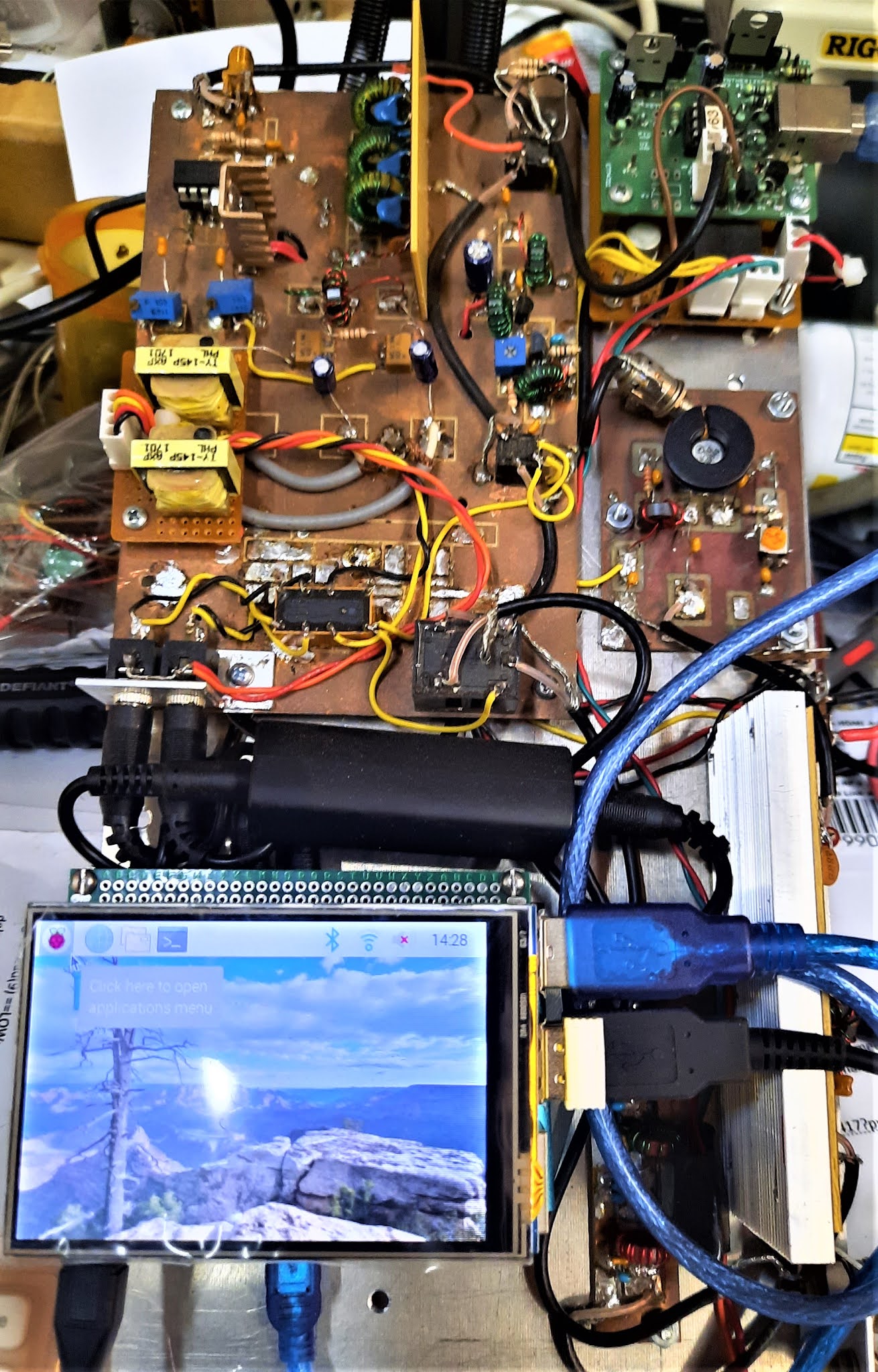
Several years ago I built The RADIG V.3 SDR that all fit on one chunk of Aluminum; but required an external HDMI display. In fact this was my 2020 back yard Field Day station as shown below.
Now with the new display I found it has suddenly shrunk in size in term of the foot print. The 3.5 inch TFT display simply plugs into the Raspberry Pi3 and we are off and running !
Actually I now have two versions of the display. One came as a $23 kit for the RPi4 and the other is intended for the RPi3 and is just the Display (about $15). THERE is a huge difference. The RPi4 version can be used with the RPi3 and is the BETTER choice. Let me explain.
There is a slight difference in the software set up --which is a problem because there is no explanation of what software to use. But some Internet Sleuthing found something the works for the RPi3 version --but it is clunky and has two problems.
Problem #1 despite what ever you do you cannot change the screen resolution and you are stuck with the default.
You cannot simultaneously use the small display and the external HDMI screen.
These two problems are ONLY with the RPI3 Version. The RPi4 version you can change the screen resolution and also have the simultaneous HDMI. The simultaneous HDMI -- is great when you want to make settings changes as they are hard to see on the small screen.
A good "show and tell" is the photo of the FT-8 screen shown in the March 21 post -- you see the whole WSJTX for FT-8 using the RPi4. But when you use the RPI3 (beacuse of the fixed resolution) you then have what is shown below. Using the mouse you can move the panel around -- but not as good as what you see in the March 21 posting.
So yes get a display; but get the one for the RPi4. If you want the secret decoder ring for the code needed to make these displays work, send me an email to my QRZ.com email address.
Yes this is a totally homebrew SDR transceiver that is capable of making not only SSB, CW but also WSPR and FT-8 all fitted to a chunk of aluminum.
I have suggested this new form has potential as a chick magnet. Just think out of the burrito box for a moment. You take this rig to a large park, find a picnic table, throw a chunk of wire over a nearby tree branch and just wait for the chicks to come. Wish I had this jewel when I was 18 years old!
73's Pete N6QW
March 21 ~ Small Footprint SDR
The rig is a Soft Rock Ensemble (40-30-20M) at 1 watt. All else a $14 Sound Card and the RPi3 + Treedix Display. Imagine this on a park bench this summer -- A real Chick Magnet!
This is a WSPR shot of my Transmitted signal at 1 watt this morning! I was heard in Japan.
Visit this website as it contains Six presentations made to ham clubs and organizations. Several are solo and several are with N2CQR.
Pete N6QW
March 18, 2021
FT-8 using the SoftRock V6.3 ng along with a RPI3 running the latetst OS and the Treedix Display
This is a really small footprint SDR. Imagine this in your shack. You can do it!!!!
SDR XCVR "Al Fresco" with Display. A Totally Homebrew 5 Watt SDR!
Just as time moves forward, which is unstoppable, so is what is happening within the homebrew community. I know of at least 5 major groups who are working in earnest to deliver a homebrew SDR transceiver including several that will be unveiled before Independence Day. Think of Giants like Bob Larkin (one of the EMRFD guys) and of course Farhan who are dipping their oars into the SDR waters. This takes it to a new level because of who is doing this with their technical expertise and their well known accomplishments.
Below is a slide from a presentation I made this past weekend to the Long Island CW Club. The theme was Roll Your Own Rig!
This is the premise of this post. On the left we have a homebrewed CW Transceiver with a superhet receiver including a 3 Pole Crystal Filter and a Crystal Controlled 1 watt Transmitter. All of this goodness is but a few boards on a wooden plank! But it is still limited by a single rock and a single BW of the Crystal Filter. This does not raise the excitement level very much (and it didn't with the CW club).
On the right (lower left) is a 5 Watt homebrew SDR transceiver which also is on a wooden plank and but a few boards. That SDR can do CW and SSB as well as AM, FM and Digital. All this with the magic of a Raspberry Pi3 doing all of the heavy lifting. But much more are all of the extra goodies like a Spectrum Display and Waterfall.
Did I mention all of the filtering options as well as AGC, Noise Blanker (actually 3 Blankers), and a Notch Filter. The bonus piece includes Split operation, a Record function and 200 Hz CW filter. All this is done with Free software! Did I mention with the Split and using headphones --one frequency in one ear and the other frequency in the other ear --scary!
So why screw with Analog VFO's and marginal signal handling features, when cheap technology places SDR capabilities in our hands rivaling the commercial boxes, at a far less cost?
So OK no one asked about the Fan Dancer? Actually during the presentation, I would refer back to this slide and taking a note from my graduate studies in Marketing, I hooked the audience with a singular anchor point! In the presentation all I had to say was "the slide with the Fan Dancer" and instant recognition and communication to the audience as to which slide.
Now considering SDR with cheap technology, there is a downside with that approach in that Hams now have to learn stuff beyond scrolling through 4000 ICOM 7300 Menus. Loading the software on to a RPi3 can be done by a ham with somewhat limited experience. BUT FIRSTLY, you do have to RTFM, (read the manual) and do have to watch some youtube videos. That requires patience plus logical and critical thinking. Many hams today simply want to plug and play, and exercise no effort beside flashing the plastic and awaiting the Amazon truck!
[A note here in the Fan Dancer slide, the wooden plank had all of the clearly visible good stuff but you did have to have a separate display. Now with the Treedix Display it simply plugs into the RPi3 and now that is on the wooden plank too!]
Likely many hams are already behind in that they simply want to ignore SDR and stick with their commercial boxes. Well guys most of the appliance boxes today are SDR as the manufacturers realize where the market is headed and updates and improvements are software driven from the Internet.
Open up one of the new rigs (if you dare) -- you will be surpised to see --there is very little in the way of hardware -- it is all computer chips and SMD components. But more imporatntly it is jam packed with capabilities and possibilities.
The year 2021, as we dig our way (or vaccinate our way) out of the Pandemic will soon explode with many new homebrew SDR efforts and projects.
QST will have a real problem! New ham generated projects will be SDR based and will rival the Commercial boxes the ARRL touts. The offshore advertisers will not like that some ham in Peoria, IL or Peoria, AZ has come up with an SDR that is cloud based and can be carried to a local Starbucks where "al fresco" they are working the CQ WW contest. This is all happening while sipping on a Almond Mocha, Tripple Latte, Caramel flavored iced-coffee with hardware home built costing about $200. Not a pipe dream; but a reality that time marches on...
A story from today that is very much in conflict with the past and how right was separated from wrong. Today a well known person with a large cult like tribal following brazenly walks into a bank and robs it at gun point. There are 30 witnesses in the bank as well as 5 CCTV cameras. The man walks out of the bank with the stash and then is accussed of the robbery based on the evidence. His cult followers maintain he did nothing wrong. Their argument: he was simply removing the money from one location and spending it in another!
Ridiculous and improbable as that seems, his cult followers steadfastly maintain that position . Shame on you! It was always wrong and time to reconcile -- the bank robber is guilty!
One term often heard when we look at high technology products, or ones featuring elegant sophisticated designs, describes it all and that is "German Engineering".
My 1st encounter with German Engineering was my 1966 Volkswagen Beetle that I bought shortly after returning from Vietnam (the 1st time). The spare tire is located under the hood and to my horror after having only owned it for two weeks someone stole the spare tire! I went to the VW dealership during a lunch hour and purchased a spare tire and the sales person said you better buy the lock too! I was in a hurry and so said yes-- Total Bill $50 with the lock wherein I quickly headed back to work. Only this time I locked the tire in the car. After work I went about installing the spare tire lock and spare tire. Upon opening the special spare tire lock package -- I laughed out loud and uttered German Engineering.
So here was the special spare tire lock parts: A long bolt, a piece of high strength steel chain and a high quality padlock. The installation consisted of removing a bolt that went from the spare tire well to the frame. The next step was to insert that longer bolt that came with the kit through the end link of the chain and install that bolt in place of the one removed. You were to tightly secure that bolt so that it could not be hand removed (meaning you would need a socket or a wrench to unloosen it once installed).
The next step was to pass the chain through the tire metal frame several times and the set the tire into the well while also snugging up the chain. The Final Step secure the padlock to the other end of the chain! Boom no way to get the tire out without a key for the padlock. Simple solution and a secure tire = German Engineering.
But now back to ham radio and German Engineering. I read an article in CQ magazine about WWII German field radios. In one particular design (something beyond a Walkie Talkie) for use at the local force level there appeared a unique design. It turned out there were many of these radios that were deployed. So the designers thought about the issue of a vast number of field radios and their critical role in the conduct of warfare. This brought up the need for field maintenance and repair. The ever sought for quest, quicker, better, cheaper!
The solution -- these were 5 or maybe 6 tube transceivers and the design was the same tube was used in all parts of the radio. Thus neatly packed in the cover of the radio box was one spare tube that could be used in any socket. With the radios of this era -- a blown tube was typically on the critical failure path, Solution: A spare tube in every radio. German Engineering!
After reading this article Ii tried designing a 20M "toob" SSB transceiver using the 6AK5 as every circuit elemnet. I was up to 13 tubes. But if you check, the 6AK5 has a low current requirements for the filaments. So if you series the filaments for 12 VDC operation -- it was only a couple of amps for the entire filament supply. The 13th tube had its filaments in series with the pilot lamps. I actually got the receiver working; but then ran into some issues with the transmit side. Never did finish that project; but there certainly was a lot of metal bashing.
In line with our nostalgia theme I thought about Dual Gate MOSFETs and perhaps their use in a solid state equivalent of the German Engineered military transceivers.
So I went to my most cherished publication SSDRA and toured the circuits for any applications using DGM's which show the 40673. I am proposing using the 3N204 for which I have a small stock. I have tested circuits using the 40673 and swapped in a 3N204 --works!
To my surprise I spotted some circuits that have promise. These are shown above (All from SSDRA). So we could start with a Broad Band RF amp stage that I have designed using two J310's which is easily converted to the 3N204. I could use relay steering with this circuit so it would be the Rx RF Amp on receive and the Tx pre-driver on transmit. Check that block -- it has been done.
Somewhere in there would be a Band Pass Filter which feeds a 3N204 Mixer stage and then on to a 9 MHz Filter. Check that block. But we would need a relay or solid state switch to steer signals to a single pass IF amp stage. The alternative input is from a diode ring mixer that would feed the IF Module on transmit. One position is the BPF/Mixer that feeds the IF Module and in the second position the output of the Balanced Modulator feeds the IF Module. We do have the circuit for the 3N204 IF Amp stage so check that block.
Following the IF amp stage would be the Product Detector on receive and there is a circuit for a 3N204 to do that -- check the block. But on transmit a relay would switch over to another 3N204 Mixer stage that would take the 9 MHz SSB and mix that with the LO and run that through a 2nd BPF for the transmit chain.
In my Sudden SSB transceiver I do something similar only using NE602's. See www.n6qw.com and search for the Sudden SSB transceiver.
The LO and BFO are done with an Arduino Nano and Si5351. The Driver circuit show on the hand drawn schematic would be for the transmit driver stage. The final is an IRF510.
So just noodling here I think we have five 3N204's
Receiver RF Amp Transmit Pre-Driver
Receiver Mixer
IF Amplifier (9 MHz)
Product Detector
Transmit Mixer
Other devices would be the 2N2219 Transmit Driver, 2N3904/LM386 Audio Stage. 2N3904 Mic Amp, IRF510 Final Amp. The LO/BFO comes from the Arduino/Si5351
A tip of the cap to German Engineering!
Dentron was on to Something!
Dentron out of Stow, Ohio at one time ruled the roost on Ham Amplifiers. Anyone remember or have a MLA2500 in their shack. During the early 1980's the world caught up and passed the US with new ham products that were cheap and caught our fancy. This caused many US Companies to try to move into arenas that were not their strong suit. This is like the glam movie actress who now was fifty, with sagging boobs, trying to star with a 20 something tanned hot hunk. It didn't sell well in Peoria nor Union, Missouri!
Dentron made that move from Amps to Transceivers and did have some interesting products; but likely was underfunded and just not competitive with the offshore "blinking lights and flashy knobs". Here is an example of one of the not so well known offerings from Dentron. It is called the Scout HF SSB!
BTW this is a current listing on eBay starting at $188.
Here is a tour of the innards. First it is a 5 Channel Crystal Controlled SSB Transceiver. Dentron used a basic SSB transceiver assembly (9 MHZ IF) purchased from a Japanese Manufacturer called Mizhou who made ham equipment. Their product line was walkie talkie sized SSB transceivers using VXO's.
Dentron bought the IF board then added 5 crystal channels to output in the 4 to 10 MHz range (USB Only) and inside that box is a 100 watt PA. The LPF as seen in the photos likley is insufficient to meet today's FCC specifications. The target market was like the CAP or industrial users.
It is barebones and lacks some basic controls like a clarifier, or microphone gain control. It looks like on the back panel you can make CW -- but likely not very good.
BUT they were on to something that could have been, had it been done today. Suppose you drop the crystal board and install an Arduino / Si5351 --- that would open up the spectrum. The channel selector location could be the encoder and using the encoder push button you could band change and relay switch the appropriate filters.
Modify the speaker grill to include a Color TFT right dead center and move the speaker back from the front panel with some spacers. Ditch the pilot lamp and install a USB/LSB select switch. Make the audio gain control a dual concentric pot with the outer ring being mic gain and the inner ring the audio. I would add a mini momentary pushbutton right below the meter as a TUNE button.
But my plan would have a few caveats. This is not ladies panty hose as one size does not fit all. Given where we are headed in the Sunspot Cycle I would make it a quad band rig to cover 40, 20, 15 and 12 meters. The 17M band was a concern because of the 9 MHz IF. With the N6QW Digital Adapter and USB, this opens up this rig to prime use for FT-8 for those so inclined.
BTW --you can find schematics of the Dentron MiniLX which was a 15 watt SSB/CW transceiver and it uses a similar board from Mizhou. For a lot of hams this is too hard (more out of laziness) so go to https://www.n6qw.com and there is a link to the Dentron MiniLX pdf so you can find it there. I find it hard to believe so many hams do not know that Google is their friend!
So for those who have never built a thing in their lives --this is your project! Jump in, solder your fingers together, burn a hole in the rug, smoke parts and place more orders to Amazon through the Solder Smoke blogspot link. This is reliving the past and it is your chance to enjoy that journey! [Caution homebrewing a HF SSB Scout could cause pedis plantis, dermitophitosis, baldness, crossed eyes, insane food cravings and borderline schizophrenia!]
So OK here is my version of the Dentron HF SSB Scout!
I think mine has some real presence.
Special Commentary: There was another ham equipment manufacturer that offered a SSB Transceiver by the name of Scout! Yes, the Ten Tec Model 555 ~ Scout. It was essentially a single band (at a time) rig which used plug in Band Modules. This Scout variant had many innovative features; but could be costly if you purchased additional band modules.
Today the problem is that a Scout is sold with a single module on eBay; but it is tough as nails to find additional modules. There is a Model 555 on eBay right now for a reasonable price but comes with a 10 Meter Module. That won't be useful for another year or two.
Having to sit in the shack for long periods, the mind often plays tricks on your well being. About a month ago I spotted a 1970's Swan MB-80A which was is single band solid state transceiver (80M) on eBay. It was dirt cheap. There is a MB-40A currently on eBay going for $350. The A series could do probably about 60 watts out and has absolutely no frills. Thus the mind challenge!
In their initial product announcement in the early 1970's, Swan had three models the MB20, MB40 and the MB80. These were 15 watt units. I immediately placed an advanced order for the MB20. About a month later I got a letter telling me that the MB20 would not be produced due to technical difficulties. I was crushed. Later on I did order an MB40.
As I found out later some of the early models used 10.7 MHz Crystal Filters from Tyco while the later ones I think used 5.5 MHz crystal filters.
The one I recently bought has a 10.7 MHz crystal filter. It was obvious the unit I have had some issue as told by the re-soldered joints and burnt wires.
I bought a manual reprint which covers the MB40A and the MB80A although the schematic is for the MB40A with the 5.5 MHz filter. But most of the parts on the board track with the schematic.
Speaking of the board --all over the board is stamped MB40A. So that suddenly gave me an idea -- a rig conversion to 40M!
My initial testing showed that the received signal was crap! The other issue --when you tune it up for max power --often instability and oscillation.
There are adjustments for the carrier oscillator --two trimmers. One trimmer set the frequency for normal SSB and the second trimmer is engaged when you switch over to CW (or tune). It shifts the CIO into the filter passband so you get an output signal when you depress the PTT. It also drifted a bit. No matter how you adjusted the Carrier Oscillator Crystal it just didn't sound right on SSB. Obviously after 50 years the crystal drifted too far!
So having done similar conversions I turned to my trusty S-5351 and came up with a sketch so that with a 10.7 MHz Filter the USB/LSB frequencies would be 10.698500 and 10.701500. I cut the trace to the onboard crystal and and connected the LO and BFO using the two calculated frequencies and still LSB didn't sound good. I tried various frequencies and the result was the same.
So at about 3 AM my brain awakened me and said here is the answer. Very likely the 10.7 MHz crystal filter was set for LSB and since I was placing the LO above the 80 M band there was a sideband inversion so that the normal USB crystal was now being used for LSB. But the Crystal Filter wanted to see the LSB BFO since is was a LSB tending filter.
I had seen this problem on a Bitx40 that I fitted for USB/LSB. So a code rewrite. The 10.701500 is a fixed BFO used for both USB and LSB. For LSB I use a 6.9 MHz LO that mixes with incoming at 3.8 MHz to produce a 10.7 MHz IF.
For USB I set the LO at 14.5 MHz which causes a sideband reversal (14.5 - 3.8 = 10.7) but with the same BFO frequency results in USB. The why of USB --- FT-8 and WSPR and the potential of 40M FT-8..
I am awaiting for later today when the band opens to see if my handiwork did indeed bear fruit. Once I get 80M working then I will see about moving the rig to 40M. I think many of the tuned circuits can be easily shifted to 40M.
I tested the 80M signals and they are spot on and it is nice to see the potential of making this work on 40M. Another nut to crack was that the BFO frequency was physically shifted for CW (a band switch engages a second trimmer cap in CW). So we can take that switch contact and make that an input to the Arduino, Now the the BFO gets shifted for tune and CW. I love it when a plan comes together!
73's
Pete N6QW
Ground Hog Day ~ Bill Murray will not be present!
*********
02/06/2021 | Ground Hog Day Special Event
Feb 6, 0900Z-1500Z, K3HWJ, Punxsutawney, PA. Punxsutawney Amateur Radio Club. all modes,
all bands. Certificate. Stephen Waltman, KB3FPN, 37 Clark St., Brookville, PA 15825. SASE for
certificate. www.punxyclub.com
Having a CNC Mill in your Shack soon will be like having a DVM or SWR Bridge! Covid19 has forced many of us to SITS and so what do you do now when you have toured every menu on your appliance box?
The simple answer is build something. The next problem with so many of today's ham's -- "I can't build anything as I don't have a circuit board". That excuse is now removed! With free software and literally thousands of you tube videos -- get off the ICOM 7300 menu button and build something!
A Russian Germanium UHF Single Transistor 20M (14.060 MHz) Transmitter built in 15 Minutes. Pout = 1.5V PTP which equals 5.625 milliwatts into a 50 Ohm load. Circuit is shown later. An afterburner is planned to move the Pout to about 100 milliwatts. Note the island squares fabricated on my CNC using a scrap piece of PCB and also note the + voltage goes to Ground!
Opportunities for error before you copy something from the Internet abound. So you have decided to build a one transistor transmitter and you happen to have a 2N2905A PNP transistor which can sink 600ma. (Good potential as an oscillator.) So you search the Internet and out pops this circuit. A couple of resistors are a small outlay, some of which you will have to determine. But if you want to put this on 14.060 MHz then you will need to calculate the value of L1. the tap is usually 25 to 33% from the source end and the output tank L2, is usually 2 to 4 turns wound over L1. The full turns of L1 plus the 10PF and the internal junction capacitance plus strays would figure in for the calculation as to the inductance from which you can find out how many turns. Figure a 3/4 inch diameter air wound coil. You might want to make C1 a small trimmer cap that you would adjust for the best sounding note.
Now take a good hard look at this circuit which was directly lifted from the internet (unchanged) -- do you see any thing hinky? (Hint it is a PNP Transistor). [So OK the battery + side goes to ground with a PNP. You will smoke the transistor (possibly) if you connect as shown; but it definitely will not work. The + always gets to the emitter with a PNP. So here is that opportunity to get the wrong information.].
This second example, also from the Internet, shows the correct battery polarity. See you learned something already! Note the + side to ground. In case you failed to memorize this circuit as part of the Extra Exam -- It is a Colpitts Oscillator. The Colpitts always has TWO C's -- one from base to emitter and the other from the Emitter to Ground. They serve as a part of the Barkhausen Criteria where kB=1 and this feedback is sufficient to cause oscillation. C1 enables what is called a VXO (Variable Crystal Oscillator).
The change in the series capacitance C1 works with the internal capacitance and inductance of the Crystal itself to cause the normal oscillating frequency to change by a few percent. Typically the shift is small with lower crystal frequencies changing by maybe 1 or 2 kHz for those less than 10 MHz and crystals above 10 MHz may be changing by as much as 5 or 10 kHz. Certain crystal types are suitable for larger frequency swings. Try to find crystals in the larger cans versus the shorter as they tend to have a greater frequency excursion.
The photo of the transmitter shown earlier uses this schematic. Parts substitution IUWIH. C2 = 100 pF, C3 = 130 pF, L1 = 1mH, Q1 = Ge PNP UHF, R1 = 33K.
I happen to own a $250K CNC milling machine but you can buy one for about the cost of 10 trips to McDonald's takeout and you will have a CNC machine in your shack.
Today I spotted machines on Amazon ranging in price from $179 (lite fare at MickieD's typical of us coasties) to about $390 ( The bill of fare likely to be seen in the Mid-west ). Likely the $350- $390 ones are the more durable and one from SaintSmart is owned by a fellow ham.
Got to the SolderSmoke Blogspot and Click on the Amazon block and search for CNC Milling Machines.
The following were all built on my machine and are easily built on one of the current crop of machines.
Covid19 will be with us for at least another nine months --go buy that machine and build that rig!
73's
Pete N6QW
PS My machine actually cost $3K and it was built by my ME son. The $250K was the bill to send him to college for 5 years.
How it used to be done! Four Tube (TOOB) SSB transmitter with 10 Watts output, See Editor's and Engineers, Radio Handbook, 18th Edition (W6SAI), and the Transistor Radio Handbook from Les Earnshaw (ZL1AAX) and Don Stoner (W6TNS) circa 1963.
This predates the IC-705 and the FTdx10. (Costs less too!)
Happy New Year!
73's
Pete N6QW
December 26 --- Fun With Homebrew Rigs.
Thanks Wes & Terry!
Christmas 2020 ~ Pasta Pete at Work.
***
Enter the Backpack SDR Project! What a great way to end 2020 and to light off 2021.
This SDR project involves the use of the Teensy 4.0 or 4.1 along with COTS (Commercial Off The Shelf) hardware to form a SDR Transceiver. It will eventually have a waterfall and spectrum display (ILI9341 or ILI 9488) that are TOUCH SCREEN displays.
A word about the COTS -- the main receiver board with the BPF's and LPF's come from QRP Labs (Hans Summers) a companion Transmit Board is in work and all else comes from Banggood * in China and eBay.
I hope to test drive the Backpack SDR only using my RADIG board in lieu of the separate Tayloe Detector Rx and Tx Boards. I have the ILI9341 but awaiting the ILI9488. This could be exciting and a new SDR to arrive on scene for 2021.
TOTL
73's
Pete N6QW
* Any one else snicker every time that word appears in print?
This is not about radio stuff! Next week we will start the Holiday Season with Thanksgiving and in about a month will be Christmas. Please follow the CDC advice about Holiday gatherings. Simply stated, DON'T travel or have large gatherings.
But I want to reflect about a Holiday gathering on December 24th 1945. It was a celebratory day as just a week before I turned four years old and on that day, my Dad and four Uncles had all returned home from the war -- all were alive and looking forward to restarting their lives.
The first question I asked my Dad was if I was going to get a "knife gun" for Christmas which was the next day. He said something to me which I have never forgotten: "He said Petey, (the name I was always called, as his name was Pete too) you never want a knife gun, as it has only one purpose and that is to kill others."
Fast forward exactly 20 years and in December 1965 there I was in Chu Lai, South Vietnam surrounded by knife guns. It was only 20 years from that special Holiday gathering and in between we had the Korean Conflict.
Today we have Donald John Trump, while not using a "knife gun" is attacking the foundations of our Democracy. He never served this country either as a part of the military or what he is doing today as Commander in Chief. He is just a sore, one term LOSER! History will not treat him kindly.
Trump -- Numbers Don't Lie! You Lost, so now get out of the way and make way for a real President! Stop Golfing and Concede!
Emily Murphy -- get a pair and certify ascertainment. Your 15 minutes of fame are over!
Finally, Rudy you need to get new brand of hair dye --and your 15 Minutes were over a very long time ago.
*****
Be safe: Wear a Mask, Social Distance, Wash Your Hands, Avoid Gatherings.
******
Late breaking news.. I have now downloaded a different software to control the HL2. It is called OpenhpSDR-PowerSDR and a free download. (Updated 11/18/2020)
If you have used Power SDR it is based on that platform. I do not have all of the boxes checked; but it is receiving, It uses a Windows 10 platform but I think there is a Linux Variant. I have a small Windows 10 machine that was mostly useless -- but no more.
I have definitely moved to the dark side of this hobby with my taking up the SDR baton (cudgel is more like it) full time; but that actually goes back to over four years ago. The Hermes Lite 2.0 (HL2) is one of the New Technology Devices for 2020.
SDR is here and an uptown HL2 SDR real world transceiver can be had for about $300. Here are some points to ponder as to what tilts the decision to this excellent radio.
Firstly it is not a kit where you have to solder almost invisible SMD parts. There is some assembly required like drilling one hole is the case to attach a heatsink and to install the two boards inside the case -- 8 screws. [When purchasing the HL2 get the main board, the N2ADR filter board, the assembly ($1) and the case. That comes to just shy of $300. With the shipping by air --about $330 turnkey.]
After installing the FREE SDR software such as QUISK you open up a whole host of options such as the Spectrum Display and the colorful Waterfall. I can look at a slice of a ham band (384 kHz) or one button lets you look at the whole HF spectrum with the Band Scope. This is important for seeing if the band is totally dead or you are simply in a dead spot.
The rigs specifications are impressive in that you have a real 5 watt radio that is multi-band, multi-mode and comes complete with all of the filtering you could ever want
It works especially well with the digital modes and I have been enjoying FT-8 operation on many bands. In fact I am seeing FT-8 signals on 12 Meters. I have made both FT-8 and SSB contacts on 17 Meters using only 5 watts!
Some bonus features added to the QUISK dashboard. Built into the HL2 and the QUISK software is the capability to measure the Power Output and the SWR. I find that very useful.
You have many options for the computer to drive the HL2 ranging from the Big Box supercomputers to the diminutive Raspberry Pi3. BTW for the RPI3 --it is cranking, so add the external cooling fan. I have used three SBC's with the HL2 including the RPi3, Asus Tinker Board and the amazing $40 Atomic Pi. They all work! My really big set up has a supercomputer with two screens --should have bought the 72 inch screen! With a wireless mouse with a scroll wheel I recently discovered the wheel is like a tuning knob with a 50 Hz step tuning rate. So cool. You cannot operate the HL2 standalone --you must have a computer!
You will also need a router or network switch to interface between the computer and the HL2. The one in the photo above can connect four separate computers to the HL2 and was (gulp) only $15. So you can operate the HL2 from four different locations in your home. One 6 Land ham is working on sitting a his local Starbucks with his I-Phone and using the HL2 at his home shack-- still experimental but shows promise. His I-Phone running the HL2 will soon replace the beret as a chick magnet.
But the real test --how does it hear and how does it sound? High marks for both. In fact I had a 1/2 hour QSO on 17 Meters with a ham running a FLEX 6700, a big amp and a big beam. He picked and poked at everything and then said --you really sound good and hard to believe you are running only 5 watts. Having a creditable signal on the higher HF bands separates the Big Dogs from the yelping puppies!
Additional functionality includes a port for control of an external linear amp and I do believe the HL2 can run as a VNA --a couple of ports on the front panel to do that. I have not explored that --but in time.
Check out the Hermes Lite Google Group as that is an excellent source of information and current information of availability of the HL2. This radio comes from China and is built in blocks. The last block release #9 was in October so you might have to wait for the next release. But get one!